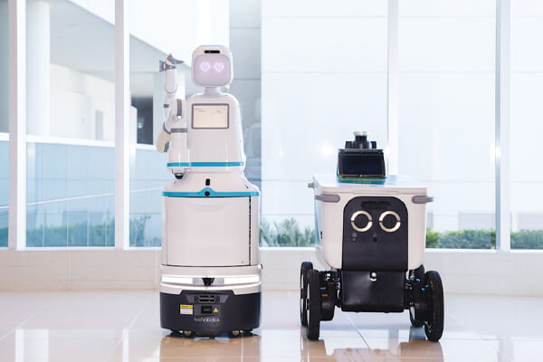
Mobile robots are becoming an essential part of modern industrial automation. From autonomous mobile robots (AMRs) and automated guided vehicles (AGVs) to warehouse transportation systems, hospital delivery robots, and industrial material-handling equipment, mobile robots are helping businesses improve transportation efficiency, reduce manual labor, and build more flexible production environments.
However, the performance of a mobile robot depends on more than its navigation system, sensors, or intelligent control software. Its drive system plays an equally important role. A robot must be able to start smoothly, accelerate under different payload conditions, maintain a stable travel speed, navigate inclines, stop accurately, and remain stationary when required.
These operating requirements place considerable demands on the motor and transmission system.
For this reason, integrated DC servo motors with planetary gearboxes and electromagnetic brakeshave become an attractive option for mobile robot manufacturers. By combining brushless motor technology, electronic drive control, mechanical speed reduction, and braking functions into a compact assembly, this configuration helps simplify the motion-control architecture while addressing several important requirements of AGV and AMR applications.
Compared with conventional solutions that use separate motors, drivers, gearboxes, encoders, and braking components, an integrated drive solution can reduce installation complexity, simplify electrical connections, and make mechanical integration easier.
More importantly, the combination of a DC servo motor, planetary gearbox, and electromagnetic brake provides a practical balance between driving torque, speed control, installation space, and stationary holding capability.
In this article, we examine the characteristics of mobile robots, their motor requirements, the different types of integrated DC servo motors, the advantages of integrated BLDC motor technology, and the key factors manufacturers should consider when selecting a geared DC servo motor with an electromagnetic brake.
1. What Are Mobile Robots and What Makes Their Drive Systems Different?
Mobile robots are automated machines designed to move materials, products, equipment, or other objects between different locations. Unlike traditional industrial robots that operate from fixed positions, mobile robots use wheels, tracks, or other drive mechanisms to travel through working environments.
They may operate independently through intelligent navigation systems or follow predefined routes according to programmed instructions.
Today, mobile robots are widely used in manufacturing, warehousing, logistics, healthcare, agriculture, and commercial automation.
Common types include:
Autonomous Mobile Robots (AMRs): Use LiDAR, cameras, sensors, and navigation software to identify their surroundings and dynamically plan routes.
Automated Guided Vehicles (AGVs): Follow predefined paths using magnetic strips, QR codes, laser navigation, or other guidance technologies.
Warehouse Transportation Robots: Move cartons, pallets, containers, and materials between storage and production areas.
Hospital Delivery Robots: Transport medical supplies, medications, meals, and other materials within healthcare facilities.
Industrial Inspection Robots: Travel through industrial environments to inspect machinery, infrastructure, and equipment.
Mobile Lifting Robots: Combine transportation and lifting functions to handle heavy materials or production equipment.
Although these robots have different mechanical structures and operating purposes, their drive systems share several important characteristics.
1.1 Frequent Starting, Stopping, and Direction Changes
A mobile robot rarely operates at a constant speed throughout an entire working cycle.
A typical transportation task may involve starting from a charging station, accelerating along a warehouse aisle, slowing down near an intersection, stopping at a loading position, and reversing direction after unloading.
This process may be repeated hundreds or even thousands of times during daily operation.
Consequently, the drive motor must provide:
Sufficient starting torque.
Smooth acceleration and deceleration.
Stable speed regulation.
Responsive directional control.
Reliable operation under repeated load changes.
Appropriate thermal performance during continuous operation.
A DC servo motor with a suitable controller can provide the dynamic response required by these operating conditions.
1.2 Different Payloads and Changing Mechanical Loads
Unlike some fixed industrial machines, mobile robots frequently operate with changing payloads.
For example, an AMR may weigh 150 kg without cargo but carry an additional 300 kg during transportation. Its driving resistance, acceleration requirements, and braking demands change accordingly.
The motor must provide sufficient torque to handle the maximum expected load without excessive current consumption or overheating.
This is one reason why a planetary gearbox is valuable in mobile robot drive systems. It increases output torque while reducing rotational speed, allowing manufacturers to match the motor's operating characteristics to the requirements of the driving wheels.
1.3 Limited Installation Space
Mobile robot manufacturers need to fit multiple components inside a relatively compact chassis.
These components may include:
Battery packs.
Main controllers.
Navigation sensors.
Safety scanners.
Communication modules.
Drive motors.
Gearboxes.
Braking components.
Electrical wiring.
Using separate motors, drivers, gearboxes, and brakes can increase the number of mounting positions and electrical connections.
An integrated DC servo motor can reduce this complexity by combining the motor and driver into one assembly. When matched with a planetary gearbox and electromagnetic brake, it can provide a more compact drive configuration.
This is particularly useful for low-profile AMRs, narrow-aisle warehouse robots, and compact indoor delivery robots.
1.4 Reliable Stopping and Stationary Holding
Stopping a mobile robot is not the same as keeping it stationary.
During normal operation, the motor controller can decelerate the robot by controlling motor torque and speed. However, when electrical power is removed, the motor may no longer provide active holding torque.
This becomes a potential problem when a robot stops on an inclined surface or carries a heavy payload.
A spring-applied electromagnetic holding brake can help solve this problem. When the brake coil is energized, the brake releases. When power is removed, the internal spring mechanism applies braking force to hold the motor shaft.
For AGVs and AMRs that need to remain stationary during parking, loading, unloading, or power interruptions, this function is particularly important.
One-Stop Integrated DC Servo Motor Solution Provider
Shaft
Lead Screw
Module
Linear Motion
Brake
Gearbox
Worm Gearbox
Wires
Protect Level
Protect Level
2. What Functions Should a DC Servo Motor Provide for Mobile Robots?
When selecting a motor for an AGV or AMR, manufacturers should look beyond rated voltage and power.
The motor must match the robot's mechanical structure, driving requirements, control architecture, and working environment.
A suitable integrated DC servo solution should provide several essential functions.
2.1 High Starting Torque for Heavy Loads
Starting torque directly affects whether a mobile robot can move smoothly from a stationary position.
When a robot carries a heavy payload, it must overcome the combined resistance of the vehicle weight, wheel friction, floor conditions, and any gradient.
If the motor does not provide sufficient torque, the robot may experience delayed starting, unstable movement, excessive current consumption, or motor-driver protection faults.
A planetary gearbox helps increase the torque available at the wheel.
For mobile robots, the gearbox ratio should be selected according to the total vehicle weight, wheel diameter, required acceleration, and maximum climbing gradient.
2.2 Accurate Speed Control
Mobile robots need different travel speeds for different operating conditions.
For example, an AMR may travel quickly along an open warehouse aisle but reduce its speed when approaching workers, shelves, intersections, or loading stations.
An integrated DC servo motor with suitable closed-loop control can regulate motor speed according to commands and feedback signals.
Depending on the motor design, feedback may come from Hall sensors or an encoder.
The main advantages include:
More consistent travel speed.
Improved low-speed control.
Better acceleration and deceleration response.
Reduced speed fluctuations under changing loads.
More predictable movement during repeated transportation cycles.
For robots requiring precise positioning, manufacturers should also evaluate encoder resolution, position-control capability, and the compatibility of the drive system with the navigation controller.
2.3 Electromagnetic Braking and Holding
A mobile robot needs a reliable method of remaining stationary after completing a movement command.
A spring-applied electromagnetic brake provides mechanical holding capability without requiring continuous electrical power to maintain the brake's applied state.
This is particularly useful for:
Parking on inclined surfaces.
Holding a robot during loading and unloading.
Preventing unwanted movement during power interruptions.
Maintaining stationary conditions during temporary stops.
Supporting mobile lifting and material-handling operations.
It is important to distinguish between a holding brake and a dynamic service brake. A standard motor holding brake is generally designed to hold a stationary shaft, not repeatedly stop a moving robot from high speed.
The motor controller should normally manage operational deceleration, while the brake provides the required mechanical holding function. Emergency stopping must be designed according to the robot's complete safety architecture.
2.4 Integrated Electronic Control
Modern mobile robots require close coordination between their drive motors and main controllers.
An integrated DC servo motor with a built-in driver can simplify this process by combining the motor and electronic control components into one assembly.
Depending on the product configuration, manufacturers may obtain functions such as:
Speed control.
Direction control.
Current monitoring.
Overload protection.
Overtemperature protection.
Encoder feedback.
Fault reporting.
Communication with the main controller.
These functions help reduce external wiring and make it easier to standardize the robot's electrical architecture.
2.5 Industrial Communication Compatibility
Communication between the motor and the main controller is essential for modern mobile robot systems.
Common communication options include:
Communication Protocol
Typical Application
CANopen
AGV and AMR distributed motion control
RS485
Industrial motor communication
Modbus RTU
Communication with industrial controllers
Pulse/Direction
Basic motion command systems
CANopen is particularly relevant to mobile robotics because it allows the main controller to exchange motion commands, operating information, and diagnostic data with distributed drive devices.
However, communication support varies by motor model. Manufacturers should confirm the exact protocol, control modes, electrical interfaces, and communication documentation before purchasing.
Integrated DC servo motors are available in different configurations to meet the requirements of mobile robots with different payload capacities, installation dimensions, travel speeds, and control architectures.
For AGV and AMR manufacturers, choosing the correct motor type is an important step in developing an efficient drive system.
The main differences involve motor technology, control method, transmission structure, braking configuration, and integration level.
3.1 Integrated Brushless DC Servo Motors (BLDC)
Integrated BLDC servo motors combine a brushless DC motor with an electronic driver and, depending on the model, a feedback device.
The motor uses electronic commutation rather than mechanical brushes, making it suitable for applications requiring frequent starting, stopping, and continuous operation.
Their main characteristics include:
High power density.
Good energy efficiency.
Reduced brush-related maintenance.
Stable speed-control performance.
Compact mechanical construction.
Compatibility with closed-loop control.
Options for planetary gearboxes and electromagnetic brakes.
For mobile robots, integrated BLDC servo motors are particularly attractive because they provide a practical balance between motor performance, installation space, and maintenance requirements.
When combined with a planetary gearbox, they can deliver the output torque needed for AGV and AMR transportation systems.
Adding an electromagnetic brake provides stationary holding capability for robots operating on inclines or handling heavier payloads.
Integrated closed-loop stepper servo motors combine a stepper motor, driver, and encoder feedback system in one assembly.
Unlike traditional open-loop stepper motors, closed-loop stepper systems use feedback to monitor actual motor movement and correct positioning errors when the control system supports the required function.
Their main characteristics include:
High holding torque at low speeds.
Accurate incremental motion control.
Encoder-based position feedback.
Reduced risk of undetected step loss.
Compact motor-driver integration.
Good performance in intermittent positioning applications.
These motors are suitable for mobile robots that require controlled mechanical adjustments in addition to transportation.
For example, an AMR equipped with a lifting platform, adjustable conveyor, or automatic positioning mechanism may use integrated closed-loop stepper motors for auxiliary motion axes.
However, for the primary driving wheels of heavier mobile robots, BLDC servo motors are often more suitable when higher continuous speed, power density, and sustained transportation performance are required.
Typical applications:
Small mobile robots.
Auxiliary lifting mechanisms.
Positioning platforms.
Automatic loading and unloading modules.
Robotic grippers and adjustment mechanisms.
3.3 Integrated Brushed DC Servo Motors
Integrated brushed DC servo motors combine a brushed DC motor with an electronic driver and, depending on the design, feedback components.
They use mechanical brushes and a commutator to achieve motor commutation.
Their advantages include relatively simple control characteristics, straightforward DC power supply requirements, and established technology.
However, brush wear creates additional maintenance requirements compared with brushless alternatives.
For mobile robots operating for long periods or performing frequent transportation cycles, manufacturers should carefully consider brush service life and maintenance accessibility.
Some integrated DC servo motors are configured with planetary gearboxes to increase output torque and reduce rotational speed.
This configuration is particularly useful when the motor itself operates at a higher speed than the robot's driving wheels require.
Its main characteristics include:
Higher output torque.
Compact transmission structure.
Multiple reduction ratio options.
Coaxial input and output arrangement.
Suitability for limited installation space.
The gearbox can be matched with BLDC or other suitable DC servo motor platforms according to the application.
Typical applications:
Heavy-duty AGVs.
Warehouse AMRs.
Mobile transportation platforms.
Industrial material-handling robots.
3.5 Integrated DC Servo Motors with Planetary Gearbox and Electromagnetic Brake
This configuration combines a DC servo motor, integrated driver, planetary gearbox, and electromagnetic holding brake.
It is particularly suitable for mobile robots that need both high output torque and reliable stationary holding.
Its main advantages include:
Compact drive assembly.
High gearbox output torque.
Electronic speed regulation.
Reduced external wiring.
Mechanical holding capability.
Simplified drive-system integration.
For robots carrying heavy payloads or operating on inclined surfaces, the electromagnetic brake is an important additional function.
The brake must be correctly selected according to the required holding torque, wheel radius, gearbox ratio, maximum slope, and total vehicle weight.
Typical applications:
Heavy-duty AGVs and AMRs.
Industrial transportation robots.
Mobile lifting platforms.
Warehouse material-handling equipment.
Mobile robots requiring stationary holding.
3.6 How to Choose Between Different Integrated DC Servo Motor Types
The most suitable motor depends on the robot's primary motion requirements.
Motor Type
Main Advantages
Suitable Applications
Integrated BLDC servo motor
High efficiency, compact design, low brush-related maintenance
AGVs, AMRs, transportation robots
Integrated closed-loop stepper servo
Good low-speed torque and feedback-based positioning
Auxiliary motion and positioning systems
Integrated brushed DC servo
Straightforward DC operation and established technology
Compact, cost-sensitive equipment
Integrated geared DC servo
Higher output torque and reduced speed
Material-handling robots
Integrated geared DC servo with brake
High torque and stationary holding capability
Heavy-duty AGVs, AMRs, mobile lifting systems
For most mobile robot applications requiring continuous transportation, relatively high power density, and reduced maintenance, integrated BLDC servo motors with planetary gearboxes are a strong option.
When the robot also needs to remain stationary on slopes or hold a load during temporary stops, adding an electromagnetic brake provides an additional mechanical holding function.
An integrated BLDC motor with planetary gearbox and brake is a motion-control assembly that combines a brushless DC motor, a mechanical speed-reduction mechanism, and an electromagnetic braking unit.
Depending on the product design, the electronic motor driver and feedback components may also be integrated into the motor housing.
Each component performs a different function, but their combined operation provides a practical drive solution for mobile robots.
4.1 BLDC Motor: Efficient and Reliable Power Generation
A Brushless DC (BLDC) motor uses electronic commutation instead of mechanical brushes and a commutator.
Unlike conventional brushed DC motors, BLDC motors do not have brushes that require regular replacement.
Their main advantages include:
High power density: BLDC motors can provide substantial output power relative to their size, making them suitable for compact mobile robot chassis.
Reduced mechanical maintenance: The absence of mechanical brushes eliminates brush wear and related maintenance.
High efficiency: Properly selected BLDC motors can achieve high operating efficiency, helping mobile robots make better use of battery capacity.
Good speed-control performance: Electronic commutation allows the controller to regulate motor operation across different speeds and loads.
Long operating life: With appropriate electrical, thermal, and mechanical design, BLDC motors can provide reliable operation over extended working periods.
These characteristics make BLDC technology attractive for mobile robots that need frequent starting, stopping, and speed adjustments.
4.2 Planetary Gearbox: Higher Torque in a Compact Structure
A planetary gearbox is a mechanical transmission system consisting of a sun gear, planetary gears, a ring gear, and a planet carrier.
Its coaxial input and output arrangement makes it suitable for applications where installation space is limited.
Compared with some conventional gear transmission structures, planetary gearboxes offer several advantages.
High torque density
Multiple planetary gears share the transmitted load, allowing the gearbox to deliver relatively high output torque within a compact structure.
Compact dimensions
The coaxial design helps simplify installation and mechanical connection with the BLDC motor.
Multiple reduction ratios
Different planetary gear stages can be combined to achieve the required output speed and torque.
Good transmission efficiency
A properly designed planetary gearbox can provide high mechanical transmission efficiency, reducing energy losses.
Stable mechanical performance
Appropriate gear materials, bearing arrangements, lubrication, and manufacturing precision contribute to reliable operation under repeated load cycles.
For mobile robot manufacturers, the main benefit is straightforward: the gearbox allows a relatively high-speed motor to drive the wheels at a lower speed with higher output torque.
The gearbox ratio must be carefully selected. A higher reduction ratio increases torque multiplication but reduces output speed.
An electromagnetic brake is designed to control or hold the rotation of the motor shaft.
For mobile robot applications, a common configuration is the spring-applied, electromagnetic-release brake.
Its working principle is relatively simple:
When the brake coil is energized, electromagnetic force releases the brake.
The motor shaft is allowed to rotate.
When the electrical supply is removed, the spring mechanism applies the brake.
The brake generates mechanical holding torque.
This design is particularly useful when a mobile robot needs to remain stationary after power is removed.
Important brake specifications include:
Rated brake voltage.
Static holding torque.
Brake release time.
Brake engagement time.
Coil power consumption.
Allowable operating temperature.
Mechanical installation dimensions.
Permitted dynamic braking energy, if applicable.
For mobile robots operating on slopes, brake selection should be based on the actual holding torque required at the wheels rather than simply choosing a brake according to motor power.
When selecting a drive motor for a mobile robot, manufacturers need to consider more than rated power and maximum speed. The motor must provide sufficient starting torque, maintain stable movement under changing loads, support accurate speed control, and stop the robot safely when required.
For these reasons, many mobile robot manufacturers consider an integrated BLDC motor with a planetary gearbox and electromagnetic brake a practical drive solution. It combines several motion-control functions in one compact assembly, helping simplify mechanical design while meeting the demands of automated mobile equipment.
5.1 Higher Output Torque in a Compact Structure
Mobile robots often operate with limited installation space. Their drive systems must fit inside a relatively small chassis while providing enough torque to move the robot, carry payloads, and overcome floor resistance.
A BLDC motor provides high-speed rotation, while a planetary gearbox reduces output speed and increases torque. This combination allows manufacturers to use a compact motor while obtaining the output characteristics required by the application.
For example, a mobile robot used in warehouse material handling may need to:
Start smoothly with a full payload.
Accelerate without excessive current peaks.
Travel across different floor surfaces.
Climb designated ramps.
Maintain stable movement during frequent stops and starts.
A properly selected planetary gearbox helps the drive system deliver the required output torque without relying on an oversized motor.
The gearbox ratio should be selected according to wheel diameter, vehicle weight, target speed, acceleration requirements, and maximum gradeability. A higher reduction ratio increases available output torque but reduces output speed, so manufacturers need to balance torque and speed rather than simply choosing the highest ratio.
5.2 Improved Position Holding and Parking Safety
Mobile robots frequently stop at workstations, loading areas, elevators, charging stations, and automated transfer points. In these situations, preventing unintended movement is important.
An electromagnetic brake provides holding torque when the motor is not energized, helping prevent the robot from rolling due to gravity or external forces.
This is particularly useful for:
AMRs operating on sloped warehouse floors.
AGVs transporting heavy materials.
Mobile robots that stop during loading and unloading.
Automated equipment that needs to remain stationary during power interruption.
Robots working around conveyors or lifting mechanisms.
Many motor brake designs are spring-applied and electrically released. When power to the brake coil is removed, the spring engages the brake; when the coil is energized, the brake releases.
However, the brake must be correctly sized for the actual holding requirement. Manufacturers should evaluate the robot's total mass, wheel radius, maximum operating slope, external forces, and required safety margin.
An important design consideration: A holding brake is not automatically a substitute for a complete safety braking system. The motor controller, mechanical braking arrangement, emergency-stop strategy, and system-level safety requirements must be evaluated together.
5.3 More Efficient Installation and System Integration
Traditional mobile robot drive systems may require separate motors, gearboxes, encoders, motor drivers, and braking components. Each additional component creates installation work and requires more wiring, mounting space, and system-level coordination.
An integrated BLDC servo motor combines multiple components into one assembly. Depending on the model, it may include:
Brushless DC motor.
Motor driver or controller.
Encoder for feedback.
Planetary gearbox.
Electromagnetic brake.
Communication interface.
This integrated structure can reduce the number of separate components in the drive system and simplify electrical and mechanical integration.
For mobile robot manufacturers, potential benefits include:
Reduced wiring complexity.
Less installation space.
Fewer separate mounting interfaces.
Simplified motor and driver matching.
Easier system maintenance.
More consistent configuration across robot models.
The actual level of integration varies by manufacturer and product series. Buyers should confirm whether the encoder, driver, brake, and communication functions are included in the selected configuration or need to be specified separately.
5.4 Stable Speed Control and Closed-Loop Feedback
Mobile robots need predictable movement, especially when operating in narrow aisles, approaching shelves, docking at charging stations, or coordinating with other automated equipment.
A BLDC motor with encoder feedback can support closed-loop speed control. The controller compares the commanded speed with the actual motor speed and adjusts the motor output to reduce deviations.
This helps mobile robots achieve:
More consistent travel speed.
Smoother acceleration and deceleration.
Better low-speed operation.
Improved synchronization between left and right drive wheels.
More predictable movement during docking and positioning.
For differential-drive mobile robots, controlling the speed of both drive wheels is particularly important. Differences in motor response can affect turning accuracy and straight-line travel.
The encoder type and resolution, control algorithm, communication cycle, and mechanical transmission accuracy all influence the final motion performance. An encoder alone does not guarantee precise robot positioning; the complete navigation and motion-control system must work together.
5.5 Better Adaptability to Different Payloads and Operating Conditions
Mobile robot manufacturers often develop several models based on different payload capacities, chassis dimensions, and application requirements. A modular motor platform can make it easier to adapt the drive system across these product variations.
An integrated BLDC motor with a planetary gearbox and brake can be configured with different parameters, including:
Rated voltage and power.
Motor speed and torque.
Gearbox reduction ratio.
Encoder type and resolution.
Brake holding torque.
Communication protocol.
Installation dimensions and shaft configuration.
For example, a lightweight warehouse AMR may prioritize compact dimensions and high travel speed. A heavy-duty AGV may require higher output torque, a suitable gearbox ratio, and a stronger holding brake.
Rather than using one motor specification for every robot, manufacturers can select different configurations within a compatible product platform. This can help standardize the electrical architecture while allowing the mechanical performance to match each application.
5.6 Lower Maintenance Requirements and Longer Service Life
Maintenance requirements directly affect the operating cost of warehouse and industrial mobile robots. Equipment that operates for long shifts or runs continuously needs a drive system that can withstand repeated acceleration, braking, and load changes.
BLDC motors do not use mechanical brushes, eliminating brush wear and brush replacement associated with brushed DC motors. This can reduce one source of routine maintenance.
Planetary gearboxes can also provide high torque density in a compact structure. However, gearbox service life depends on gear materials, bearing quality, lubrication, output loading, alignment, and operating conditions.
When evaluating a complete motor assembly, manufacturers should consider:
Motor thermal performance under continuous operation.
Gearbox rated torque and allowable peak torque.
Gearbox backlash and transmission efficiency.
Brake wear and expected engagement cycles.
Encoder reliability.
Protection rating against dust and moisture.
Operating temperature and vibration resistance.
A well-matched motor, gearbox, and brake can help improve drive-system reliability. Nevertheless, service life should be assessed using the manufacturer's technical specifications and application-specific testing rather than assumed from the motor type alone.
5.7 Easier Communication with the Robot Control System
Modern AGVs and AMRs usually work as part of a larger automation system. Their drive motors need to communicate with the main controller, navigation system, and sometimes a fleet management platform.
Depending on the motor controller, common communication options may include CANopen, RS485, and EtherCAT.
These interfaces serve different system requirements:
CANopen: Commonly used in distributed motion-control systems and mobile equipment where communication between multiple devices is required.
RS485: Useful for serial communication in industrial environments, depending on the protocol implemented by the controller.
EtherCAT: Suitable for applications requiring high-speed, deterministic communication and coordinated motion control.
Before selecting a motor, buyers should verify the supported protocol, communication objects or register map, command structure, feedback data, error reporting, and compatibility with the robot's main controller.
Communication compatibility is not determined by the physical interface alone. Two devices with an RS485 connection, for example, may still use different protocols and require additional integration work.
5.8 A Better Balance Between Performance, Space, and Total System Cost
For mobile robot manufacturers, the purchase price of a motor is only one part of the overall drive-system cost. Separate components may increase installation time, wiring expenses, mechanical design work, and maintenance complexity.
An integrated motor solution can help reduce these costs by combining several functions into one assembly.
The potential benefits include:
Evaluation factor
Potential benefit of an integrated solution
Installation
Fewer separate components and mounting interfaces
Space utilization
More compact drive-system arrangement
Torque output
Planetary gearbox provides speed reduction and torque multiplication
Parking
Electromagnetic brake supports stationary holding
Motion control
Encoder feedback supports closed-loop operation
Communication
Integrated controller options can simplify system architecture
Maintenance
Fewer separate components and no motor brush replacement
Product development
Configurable options can support different robot platforms
The actual cost advantage depends on the robot's design, required performance, production volume, and integration requirements. Manufacturers should compare the total cost of the complete drive system rather than evaluating the motor price in isolation.
5.9 More Convenient Customization for Different Mobile Robot Projects
Not every mobile robot has the same operating conditions. A warehouse AMR, hospital delivery robot, industrial AGV, and outdoor inspection robot may have very different requirements for speed, torque, protection, communication, and braking.
This is why customization capability is an important consideration when choosing a motor supplier.
Rated voltage and power according to the robot's electrical architecture.
Gearbox ratio based on wheel size and required travel speed.
Output torque according to payload and operating conditions.
Brake holding torque according to parking and slope requirements.
Encoder specifications for closed-loop control.
Communication protocols compatible with the robot controller.
Shaft, flange, and housing dimensions for mechanical installation.
Environmental protection requirements for indoor or outdoor operation.
For OEM and ODM projects, early technical communication is particularly valuable. Sharing the robot's weight, wheel diameter, target speed, maximum slope, duty cycle, and installation drawings allows the motor supplier to evaluate the application before sample production.
Ultimately, mobile robot manufacturers choose integrated BLDC motors with planetary gearboxes and brakes because they offer a practical combination of compact construction, increased output torque, closed-loop control options, and reliable holding capability. When the motor, gearbox, brake, and controller are properly matched to the robot, the result can be a more straightforward and dependable drive solution.
Different mobile robot applications place different demands on the motor, gearbox, and braking system.
Understanding these differences helps manufacturers select the correct configuration.
6.1 Autonomous Mobile Robots (AMRs)
AMRs are widely used in warehouses, distribution centers, and manufacturing facilities.
They use sensors, mapping technologies, and navigation algorithms to identify their surroundings and move along dynamically planned routes.
Their drive systems must provide:
Smooth starting and stopping.
Accurate speed regulation.
Sufficient starting torque.
Stable operation under different payloads.
Compact installation dimensions.
Reliable stationary holding.
Communication with the central controller.
An integrated BLDC motor with a planetary gearbox provides the torque and speed characteristics needed for transportation.
The electromagnetic brake adds mechanical holding capability when the robot stops at a charging station, loading position, or inclined surface.
6.2 Automated Guided Vehicles (AGVs)
AGVs are commonly used to transport raw materials, work-in-process products, and finished goods within industrial facilities.
Many AGVs follow predefined routes and perform repetitive transportation tasks.
Their motors need to provide reliable operation over frequent starting and stopping cycles.
A geared BLDC motor can help achieve the required wheel torque and travel speed, while the electromagnetic brake supports stationary holding during loading and unloading.
For AGV applications, manufacturers should pay particular attention to:
Rated voltage, such as 24V or 48V.
Rated motor power.
Rated and peak torque.
Planetary gearbox ratio.
Wheel diameter.
Maximum travel speed.
Brake holding torque.
Communication protocol.
6.3 Warehouse Transportation Robots
Warehouse transportation robots move containers, cartons, pallets, and materials between storage areas and production stations.
These robots may operate for long shifts with frequent changes in payload.
Their drive motors must maintain stable performance while balancing power consumption and thermal limitations.
The planetary gearbox helps deliver the required wheel torque, while the integrated driver can simplify the electrical architecture.
The electromagnetic brake provides holding capability when the robot stops during material transfer or temporary parking.
6.4 Hospital Delivery Robots
Hospital delivery robots transport medications, medical supplies, meals, and other materials between departments.
Their working environments are different from those of industrial AGVs.
They may need to operate in narrow corridors, elevators, shared public spaces, and areas where patients and medical staff are present.
Consequently, their drive systems should prioritize:
Low operating noise.
Smooth acceleration.
Stable low-speed movement.
Compact dimensions.
Reliable braking.
Low maintenance requirements.
BLDC motors are suitable for these requirements because of their brushless construction and electronic speed control.
A planetary gearbox can provide the required output torque, while the electromagnetic brake supports stationary holding.
6.5 Mobile Lifting and Heavy-Duty Material-Handling Robots
Some mobile robots are designed to transport heavy loads or combine transportation with lifting operations.
These applications require higher output torque and carefully designed braking systems.
A planetary gearbox can provide the necessary torque multiplication, while a spring-applied electromagnetic brake can help prevent unwanted movement when the motor is not powered.
For lifting applications, the brake must be evaluated separately for the actual load-holding requirements. A standard motor holding brake should not be assumed to provide certified load-holding or fall-protection functionality without appropriate validation.
7. How to Calculate the Required BLDC Motor Torque for a Mobile Robot
Selecting the correct BLDC motor torque is essential when designing the drive system of an AGV or AMR. If the motor torque is insufficient, the robot may struggle to start, accelerate, climb ramps, or carry its maximum payload. On the other hand, choosing an unnecessarily powerful motor can increase system costs, energy consumption, and installation requirements.
For mobile robot manufacturers, motor torque should be calculated according to the robot's total weight, wheel diameter, target speed, acceleration, rolling resistance, maximum climbing angle, and gearbox ratio.
When selecting an integrated BLDC motor with a planetary gearbox and electromagnetic brake, manufacturers should also distinguish between motor torque, gearbox output torque, and brake holding torque. These parameters serve different purposes and must be evaluated separately.
7.1 Identify the Basic Parameters of the Mobile Robot
Before calculating the required motor torque, collect the following information:
Parameter
Description
Unit
Robot weight
Weight of the robot without payload
kg
Maximum payload
Maximum weight the robot needs to carry
kg
Total moving mass
Robot weight + maximum payload
kg
Wheel radius
Radius of the driving wheel
m
Target speed
Required maximum travel speed
m/s
Acceleration
Required acceleration during startup
m/s²
Maximum slope
Steepest operating incline
Degrees
Rolling resistance coefficient
Resistance between the wheel and floor
Dimensionless
Number of drive wheels
Number of wheels providing propulsion
pcs
Gearbox ratio
Motor-to-wheel speed reduction ratio
10:1, 15:1, etc.
Transmission efficiency
Efficiency of the gearbox and transmission
%
Important: Always calculate using the maximum operating mass rather than the robot's empty weight.
For example:
Robot weight = 200 kg
Maximum payload = 300 kg
Total moving mass = 200 + 300 = 500 kg
Therefore, the mass used in the torque calculation is 500 kg.
7.2 Calculate the Total Driving Force
The robot needs sufficient driving force to overcome three main types of resistance:
Rolling resistance
Slope resistance
Acceleration resistance
The total driving force is calculated as follows:
Formula 1: Total Driving Force
F_total = F_rolling + F_slope + F_acceleration
Where:
F_total = Total required driving force (N)
F_rolling = Rolling resistance force (N)
F_slope = Slope resistance force (N)
F_acceleration = Acceleration resistance force (N)
A. Rolling Resistance
Rolling resistance is the force required to overcome friction and deformation between the driving wheels and the floor.
Formula 2: Rolling Resistance
F_rolling = Crr × m × g × cos(θ)
Where:
Crr = Rolling resistance coefficient
m = Total moving mass (kg)
g = Gravitational acceleration (9.81 m/s²)
θ = Operating slope angle (degrees)
The rolling resistance coefficient depends on wheel material, floor surface, tire deformation, bearings, and operating conditions.
B. Slope Resistance
When a mobile robot travels uphill, it must overcome the component of gravity acting along the slope.
Formula 3: Slope Resistance
F_slope = m × g × sin(θ)
Where:
m = Total moving mass (kg)
g = Gravitational acceleration (9.81 m/s²)
θ = Slope angle (degrees)
A heavier robot or steeper ramp requires greater driving force. This factor is particularly important for AGVs operating on loading ramps, warehouse platforms, and outdoor roads.
C. Acceleration Resistance
When a robot accelerates from a stationary position or changes speed, additional force is required to overcome inertia.
Formula 4: Acceleration Resistance
F_acceleration = m × a
Where:
m = Total moving mass (kg)
a = Required linear acceleration (m/s²)
For mobile robots that frequently start and stop, acceleration resistance should not be ignored.
7.3 Convert Driving Force into Wheel Torque
After calculating the total driving force, convert it into the torque required at the driving wheel.
Formula 5: Required Wheel Torque
T_wheel = F_total × r
Where:
T_wheel = Total required wheel torque (Nm)
F_total = Total driving force (N)
r = Driving wheel radius (m)
If the robot uses two driving wheels and the load is distributed equally, the theoretical torque required from each wheel is:
Formula 6: Torque per Driving Wheel
T_each_wheel = T_wheel / N
Where:
T_each_wheel = Required torque per driving wheel (Nm)
T_wheel = Total wheel torque (Nm)
N = Number of driving wheels
For example, if the total required wheel torque is 60 Nm and the robot has two equally loaded driving wheels:
T_each_wheel = 60 / 2 = 30 Nm
Each driving wheel theoretically needs 30 Nm of output torque.
In real applications, torque distribution may not be perfectly equal because of load distribution, floor conditions, turning resistance, and wheel traction.
7.4 Calculate the Required BLDC Motor Torque with a Planetary Gearbox
A planetary gearbox reduces motor speed and increases output torque. Therefore, the required motor torque is lower than the torque required at the wheel.
Formula 7: Required Motor Torque
T_motor = T_wheel_each / (i × η)
Where:
T_motor = Required motor shaft torque (Nm)
T_wheel_each = Required torque at each driving wheel (Nm)
i = Gearbox reduction ratio
η = Gearbox and transmission efficiency (decimal form)
For example:
Required wheel torque per drive wheel = 30 Nm
Gearbox ratio = 10:1
Gearbox efficiency = 90% = 0.90
Calculation:
T_motor = 30 / (10 × 0.90)
T_motor = 30 / 9
T_motor = 3.33 Nm
Therefore, each BLDC motor needs to provide approximately 3.33 Nm of torque at the motor shaft under these assumed operating conditions.
Note: If the gearbox ratio is 10:1, use 10 in the formula, not 0.10. Also, make sure the efficiency is entered as a decimal. For example, 90% should be entered as 0.90.
7.5 Worked Example: Torque Calculation for a 500 kg Mobile Robot
Consider a warehouse AMR with the following specifications:
Parameter
Value
Robot weight
200 kg
Maximum payload
300 kg
Total moving mass
500 kg
Wheel radius
0.10 m
Acceleration
0.30 m/s²
Maximum slope
5°
Rolling resistance coefficient
0.02
Number of driving wheels
2
Gearbox ratio
10:1
Gearbox efficiency
90%
Assume both driving wheels share the propulsion load equally and the robot accelerates uphill at 0.30 m/s².
Step 1: Calculate Rolling Resistance
Formula:
F_rolling = Crr × m × g × cos(θ)
Substitute the values:
F_rolling = 0.02 × 500 × 9.81 × cos(5°)
Result:
F_rolling ≈ 97.7 N
Step 2: Calculate Slope Resistance
Formula:
F_slope = m × g × sin(θ)
Substitute the values:
F_slope = 500 × 9.81 × sin(5°)
Result:
F_slope ≈ 427.4 N
Step 3: Calculate Acceleration Resistance
Formula:
F_acceleration = m × a
Substitute the values:
F_acceleration = 500 × 0.30
Result:
F_acceleration = 150 N
Step 4: Calculate Total Driving Force
Formula:
F_total = F_rolling + F_slope + F_acceleration
Substitute the results:
F_total = 97.7 + 427.4 + 150
Result:
F_total ≈ 675.1 N
Step 5: Calculate Total Wheel Torque
Formula:
T_wheel = F_total × r
Substitute the values:
T_wheel = 675.1 × 0.10
Result:
T_wheel ≈ 67.51 Nm
Step 6: Calculate Torque per Driving Wheel
Formula:
T_each_wheel = T_wheel / 2
Calculation:
T_each_wheel = 67.51 / 2
Result:
T_each_wheel ≈ 33.76 Nm
Step 7: Calculate Required Motor Torque
Formula:
T_motor = T_each_wheel / (i × η)
Substitute the values:
T_motor = 33.76 / (10 × 0.90)
Calculation:
T_motor = 33.76 / 9
Result:
T_motor ≈ 3.75 Nm
Final Calculation Result:
Under the assumed operating conditions, each drive motor needs to provide approximately 3.75 Nm of motor shaft torque to deliver the required wheel torque.
This is the theoretical operating requirement, not the final motor selection. Manufacturers must still verify continuous torque, peak torque, motor speed, gearbox load capacity, thermal performance, and wheel traction.
7.6 Understand Continuous Torque and Peak Torque
Mobile robots do not operate under constant loads. They repeatedly start, accelerate, decelerate, turn, stop, and sometimes climb ramps.
Therefore, manufacturers need to evaluate both continuous torque and peak torque.
Continuous Torque
Continuous torque is the torque a motor can provide for an extended period without exceeding its allowable temperature under specified operating and cooling conditions.
It is important for:
Long-distance transportation.
Continuous warehouse operation.
Sustained uphill travel.
Heavy payload movement.
Applications with high operating duty cycles.
Peak Torque
Peak torque is the higher torque a motor can provide for a limited period, subject to the motor's current and thermal limitations.
It is important for:
Starting with a full payload.
Short acceleration periods.
Overcoming temporary resistance.
Climbing ramps.
Frequent changes in operating speed.
A motor should not be selected based only on its peak torque rating. If the application requires high torque continuously, the motor must have sufficient continuous torque and thermal capacity.
7.7 Calculate the Required Motor Speed
Torque is only one part of motor selection. The motor must also reach the required rotational speed to achieve the robot's target travel speed.
First, calculate the wheel speed.
Formula 8: Wheel Speed
n_wheel = (v × 60) / (2 × π × r)
Where:
n_wheel = Wheel rotational speed (RPM)
v = Required robot travel speed (m/s)
r = Wheel radius (m)
π ≈ 3.1416
Then calculate the required motor speed.
Formula 9: Motor Speed
n_motor = n_wheel × i
Where:
n_motor = Required motor speed (RPM)
n_wheel = Wheel speed (RPM)
i = Gearbox reduction ratio
Example:
Assume:
Target robot speed = 1.5 m/s
Wheel radius = 0.10 m
Gearbox ratio = 10:1
Step 1: Calculate wheel speed.
n_wheel = (1.5 × 60) / (2 × 3.1416 × 0.10)
n_wheel ≈ 143.2 RPM
Step 2: Calculate motor speed.
n_motor = 143.2 × 10
n_motor ≈ 1,432 RPM
Therefore, the motor needs to operate at approximately 1,432 RPM to achieve the target vehicle speed under the assumed conditions.
Manufacturers should confirm that the motor can deliver the required torque at this operating speed. Maximum motor speed alone does not guarantee sufficient torque.
7.8 Apply an Appropriate Motor Selection Margin
Theoretical torque calculations provide a starting point, but actual operating conditions may vary.
Uneven floors, wheel wear, turning resistance, load fluctuations, mechanical friction, and acceleration changes can increase the torque requirement.
A preliminary sizing formula is:
T_selected = T_calculated × K
Where:
T_selected = Preliminary selected motor torque (Nm)
T_calculated = Calculated operating torque (Nm)
K = Application-specific design factor
For example, if the calculated motor torque is 3.75 Nm and an illustrative design factor of 1.3 is used:
T_selected = 3.75 × 1.3
T_selected = 4.875 Nm
The preliminary motor selection target would be approximately 4.88 Nm.
The factor of 1.3 is an example, not a universal standard. The appropriate design margin depends on the application, operating duty cycle, load variation, motor thermal limits, gearbox rating, and manufacturer's recommendations.
7.9 Calculate Brake Holding Torque Separately
For a mobile robot equipped with an electromagnetic brake, manufacturers must calculate the brake holding requirement separately from the motor's running torque.
Motor torque drives the robot, while brake holding torque prevents unintended movement when the brake is engaged.
For a robot parked on a slope, calculate the gravitational force acting along the incline.
Formula 10: Holding Force on a Slope
F_holding = m × g × sin(θ)
Then calculate the total wheel holding torque.
Formula 11: Required Wheel Holding Torque
T_holding = F_holding × r
Combined formula:
T_holding = m × g × sin(θ) × r
For example:
Total robot mass = 500 kg
Maximum parking slope = 5°
Wheel radius = 0.10 m
Calculation:
T_holding = 500 × 9.81 × sin(5°) × 0.10
Result:
T_holding ≈ 42.7 Nm
If two drive wheels share the holding load equally:
T_holding_each_wheel = 42.7 / 2
T_holding_each_wheel ≈ 21.35 Nm
This is the theoretical holding torque required at each wheel.
The actual brake specification depends on where the brake is installed:
Motor-side brake: The planetary gearbox affects the torque transmitted to the wheel. Brake torque must be evaluated using the gearbox's mechanical characteristics and manufacturer's specifications.
Output-side brake: The brake acts directly on the gearbox output or wheel side, so its required torque is evaluated at that location.
Manufacturers should also consider the brake's rated static holding torque, allowable engagement conditions, wear, safety margin, and system-level braking requirements.
A holding brake should not automatically be treated as a dynamic service brake or emergency braking system.
7.10 Common Mistakes When Calculating BLDC Motor Torque
Several mistakes can result in an unsuitable motor selection, even when the basic formulas are correct.
Mistake 1: Using the robot's empty weight
Always include the maximum payload when calculating total moving mass.
Mistake 2: Ignoring slope resistance
A motor designed for flat warehouse floors may not provide enough torque for ramps or inclined surfaces.
Mistake 3: Selecting a motor based only on rated power
A motor may have sufficient rated power but insufficient starting torque or low-speed torque.
Mistake 4: Ignoring gearbox efficiency
Gearbox efficiency must be included when converting wheel torque into motor torque.
Mistake 5: Treating peak torque as continuous torque
Peak torque is generally available for a limited period. Continuous operating requirements must be checked against the motor's thermal performance.
Mistake 6: Ignoring wheel traction
Even if the motor and gearbox can produce sufficient torque, the wheels may slip when the available friction between the wheels and floor is insufficient.
Mistake 7: Confusing motor torque with brake holding torque
The motor and electromagnetic brake perform different functions. Both must be selected according to their respective requirements.
7.11 Work with a Motor Manufacturer to Verify the Final Selection
Torque calculations help mobile robot manufacturers identify suitable motor specifications, but the final selection should be verified against the complete operating profile.
When requesting a motor recommendation, provide the supplier with:
Total robot weight and maximum payload.
Wheel diameter and number of driving wheels.
Required travel speed and acceleration.
Maximum climbing angle.
Expected operating hours and duty cycle.
Required planetary gearbox ratio.
Brake holding torque requirements.
DC bus voltage and available current.
Encoder and communication requirements.
Installation dimensions and environmental conditions.
JKONGMOTOR can support OEM and ODM motion-control projects by evaluating motor power, output torque, planetary gearbox ratios, encoder configurations, electromagnetic brakes, and integrated driver options according to specific mobile robot requirements.
The development process can include technical evaluation, motor configuration, sample development, prototype testing, and batch production.
The key principle is to calculate the required torque at the wheel first, then work backward through the gearbox ratio and transmission efficiency to determine the required BLDC motor torque. This approach helps mobile robot manufacturers avoid undersized drive systems while preventing unnecessary motor oversizing.
8. How to Choose the Right Planetary Gearbox Ratio for AGVs and AMRs
The planetary gearbox ratio directly affects the relationship between motor speed and wheel output torque.
A higher reduction ratio generally provides greater torque multiplication but reduces the maximum wheel speed at a given motor speed.
A lower reduction ratio provides higher output speed but less torque multiplication.
The following table illustrates common reduction ratio ranges and their general characteristics.
Gearbox Ratio
Output Characteristics
Typical Application Considerations
5:1
Higher output speed, lower torque multiplication
Faster, lighter-duty robots
10:1
Balanced speed and torque
General-purpose AGVs and AMRs
15:1
Greater torque multiplication
Medium-to-heavy payload applications
20:1
Lower speed, higher output torque
Heavy-duty transportation robots
30:1
High reduction
Low-speed, high-torque applications
These are illustrative categories. The correct ratio depends on the motor's torque-speed curve and the robot's mechanical requirements.
When selecting a planetary gearbox, manufacturers should evaluate the following parameters.
Rated output torque: The gearbox must withstand the required continuous operating load.
Peak output torque: The gearbox should tolerate short-duration torque peaks during starting and acceleration.
Transmission efficiency: Higher efficiency helps reduce energy losses and unnecessary motor heating.
Backlash: Lower backlash may be beneficial for applications requiring accurate movement and frequent directional changes.
Radial and axial loads: The gearbox bearings and output shaft must withstand the mechanical forces generated by the wheel assembly.
Service life: Gear materials, lubrication, manufacturing quality, and operating conditions influence long-term reliability.
The best gearbox is not necessarily the one with the highest reduction ratio. It is the one that delivers the required torque and speed while maintaining acceptable efficiency, dimensions, and service life.
Selecting the right integrated BLDC motor with a brake is an important decision for AGV and AMR manufacturers. The motor must provide sufficient torque and speed to move the robot, while the brake must hold the equipment securely when it stops. At the same time, the integrated drive system needs to fit the robot's mechanical structure, electrical architecture, and operating environment.
A motor that performs well in a laboratory test may not necessarily be suitable for a mobile robot carrying heavy loads through a warehouse for extended periods. Manufacturers should therefore evaluate the complete operating conditions rather than choosing a motor based only on rated power or price.
The following factors provide a practical selection framework for integrated BLDC motors with planetary gearboxes and electromagnetic brakes.
9.1 Calculate the Total Robot Weight and Required Output Torque
The first step is to determine the maximum operating weight of the mobile robot.
Total moving mass = Robot weight + Maximum payload
For example:
Robot weight: 250 kg
Maximum payload: 350 kg
Total moving mass: 600 kg
The drive system must provide sufficient torque to move the 600 kg robot under its expected operating conditions.
Manufacturers should consider:
Maximum payload capacity.
Wheel diameter and wheel material.
Number of driving wheels.
Required acceleration.
Maximum travel speed.
Maximum climbing angle.
Floor conditions and rolling resistance.
Expected turning and stopping frequency.
The required wheel torque can be estimated using the following formula:
Total driving force = Rolling resistance + Slope resistance + Acceleration resistance
Required wheel torque = Total driving force × Wheel radius
For a motor equipped with a planetary gearbox:
Required motor torque = Required wheel torque per drive wheel / (Gearbox ratio × Transmission efficiency)
These calculations provide an initial motor specification. The final selection must also consider continuous torque, peak torque, motor temperature, and gearbox load capacity.
For mobile robots carrying heavy materials, manufacturers should pay particular attention to starting torque and uphill operation. A motor that can maintain the required cruising speed may still be unable to start reliably under maximum load.
9.2 Select the Appropriate Rated Voltage and Power
The motor's rated voltage must match the robot's DC power supply.
Common mobile robot power systems include 24V and 48V DC, although other voltage configurations are used depending on the equipment design.
When choosing the motor voltage, manufacturers should consider:
Battery voltage and operating voltage range.
Maximum current available from the battery.
Motor controller voltage compatibility.
Cable length and voltage drop.
Battery discharge characteristics.
Peak current during acceleration.
Electrical protection and thermal requirements.
Motor power should be selected according to the required torque and operating speed.
The relationship between mechanical power, torque, and rotational speed is:
Motor power (W) = Torque (Nm) × Speed (RPM) × 2 × 3.1416 / 60
For example, if a motor needs to deliver 3 Nm at 1,500 RPM:
Motor power = 3 × 1,500 × 2 × 3.1416 / 60
Motor power ≈ 471 W
This is the mechanical output power under the assumed operating conditions. Actual electrical input power will be higher because the motor and controller have efficiency losses.
Do not select a motor based only on its rated wattage. Confirm that the motor can deliver the required torque at the actual operating speed and within its thermal limits.
9.3 Choose the Correct Planetary Gearbox Ratio
The planetary gearbox is responsible for reducing motor speed and increasing output torque. Its reduction ratio has a direct influence on the robot's travel speed, acceleration, and climbing performance.
A higher reduction ratio generally provides:
Higher output torque.
Lower wheel speed.
Better suitability for applications requiring substantial torque at low speeds.
A lower reduction ratio generally provides:
Higher output speed.
Lower torque multiplication.
Better suitability for applications requiring faster travel.
The relationship between motor speed and wheel speed is:
Wheel speed (RPM) = Motor speed (RPM) / Gearbox ratio
For example, if the motor runs at 3,000 RPM and the gearbox ratio is 20:1:
Wheel speed = 3,000 / 20
Wheel speed = 150 RPM
The gearbox ratio should be selected according to wheel diameter and required vehicle speed, while ensuring sufficient output torque.
Manufacturers should also check the following gearbox specifications:
Rated output torque.
Maximum allowable peak torque.
Gearbox efficiency.
Backlash.
Radial and axial load capacity.
Gearbox noise and vibration.
Expected service life.
Lubrication and maintenance requirements.
For mobile robots, gearbox durability is especially important because the drive system experiences repeated acceleration, deceleration, turning, and load changes.
9.4 Determine the Required Electromagnetic Brake Holding Torque
The electromagnetic brake is an important component when a mobile robot needs to remain stationary after stopping.
For example, an AGV may need to stop on a warehouse ramp, remain stationary during loading, or hold its position while waiting for another automated process.
Manufacturers should calculate the brake holding torque according to:
Total robot weight.
Maximum parking slope.
Wheel radius.
Number of braking wheels.
Brake installation position.
Gearbox transmission characteristics.
Required safety margin.
For a robot parked on an incline, the theoretical total wheel holding torque can be calculated as follows:
Holding torque at wheels (Nm) = Total mass (kg) × 9.81 × sin(Slope angle) × Wheel radius (m)
If two drive wheels share the holding load equally:
Holding torque per wheel = Total wheel holding torque / 2
However, the required brake torque at the motor shaft depends on whether the brake is installed before or after the gearbox.
A motor-side brake uses the gearbox transmission characteristics to transfer holding torque to the wheel. An output-side brake acts closer to the wheel and must be sized according to its actual installation position.
Manufacturers should confirm the brake's rated static holding torque and allowable operating conditions with the supplier.
Important: A spring-applied electromagnetic holding brake is commonly designed to engage when its coil is de-energized and release when electrical power is applied. It should not automatically be treated as a dynamic braking system or a replacement for the robot's safety braking architecture.
9.5 Select the Right Encoder for Closed-Loop Motion Control
An encoder provides feedback about motor position and speed. It allows the integrated motor controller to compare actual motor behavior with the commanded motion.
For AGVs and AMRs, encoder feedback is important for:
Stable speed regulation.
Smooth acceleration and deceleration.
Left-right wheel synchronization.
Low-speed movement.
Repeated docking operations.
Motion coordination with the navigation controller.
Common encoder options include incremental and absolute encoders.
Incremental Encoder
An incremental encoder generates pulses as the motor rotates. The controller uses these pulses to calculate speed and relative position.
It is often suitable for applications where the robot controller maintains position information through continuous feedback and system-level initialization.
Absolute Encoder
An absolute encoder provides a position value that identifies the encoder's position within its measurement range. Depending on the design, it can retain or recover position information after a power interruption.
It may be useful in applications requiring position reference or more advanced motion-control functions.
When selecting an encoder, consider resolution, communication interface, feedback accuracy, environmental resistance, and compatibility with the motor controller.
An encoder does not independently guarantee accurate robot navigation. Final positioning accuracy also depends on wheel slip, mechanical backlash, wheel diameter consistency, navigation sensors, and control algorithms.
9.6 Check Communication Protocol Compatibility
Modern mobile robots are usually integrated into larger automation systems. The drive motor must communicate reliably with the robot's main controller.
Depending on the application, integrated BLDC servo motors may support communication interfaces such as CANopen, RS485, or EtherCAT.
Communication option
Typical application considerations
CANopen
Distributed control and communication between multiple devices
RS485
Industrial serial communication, depending on the supported protocol
EtherCAT
High-speed, deterministic communication for coordinated motion control
Before purchasing, manufacturers should confirm:
Supported communication protocol.
Communication speed and update cycle.
Command and feedback structure.
Motor status and fault information.
Parameter configuration method.
Compatibility with the robot's main controller.
Available software tools and technical documentation.
A physical communication interface does not necessarily guarantee protocol compatibility. For example, two devices may both use RS485 but implement different communication protocols.
For OEM projects, requesting the communication protocol documentation before sample testing can help reduce integration time.
9.7 Evaluate Motor Dimensions and Mechanical Installation
Mobile robots often have strict limitations on chassis dimensions and available installation space. The motor must fit the mechanical structure without interfering with wheels, batteries, sensors, or other components.
Manufacturers should review:
Motor body diameter and length.
Gearbox dimensions.
Output shaft diameter and length.
Mounting flange dimensions.
Bolt-hole positions.
Cable outlet direction.
Brake housing dimensions.
Total assembly weight.
Clearance for maintenance and replacement.
The complete motor assembly should be evaluated rather than checking the motor body alone.
For example, adding a planetary gearbox and electromagnetic brake may increase the overall length of the drive unit. This needs to be considered during the early chassis design stage.
If the standard motor dimensions do not match the robot's mechanical structure, OEM customization may be required.
9.8 Consider Protection Rating and Operating Environment
The operating environment has a direct influence on motor reliability.
Indoor warehouse AMRs generally operate on relatively clean floors, while outdoor AGVs and industrial mobile robots may encounter dust, moisture, vibration, temperature changes, and other environmental challenges.
Before selecting an integrated BLDC motor, manufacturers should evaluate:
Dust and water exposure.
Operating temperature.
Humidity and condensation.
Vibration and mechanical shock.
Corrosive substances.
Cable and connector protection.
Required IP protection rating.
For example, an IP54 motor offers a different level of protection from an IP65 or IP67 motor.
The appropriate protection rating depends on the complete installation. The motor, gearbox, brake, connectors, and cable entry points should all be considered.
A high IP rating for the motor housing does not automatically mean that the entire assembled drive system has the same protection level.
9.9 Evaluate Thermal Performance and Operating Duty Cycle
Mobile robots may operate for many hours each day. In high-duty-cycle applications, thermal performance can be just as important as rated torque.
Motor temperature is affected by:
Continuous load.
Peak current.
Operating speed.
Acceleration frequency.
Ambient temperature.
Installation space.
Cooling conditions.
Controller settings.
Manufacturers should distinguish between intermittent peak torque and continuous operating torque.
A motor that provides sufficient peak torque for a few seconds may overheat if it is required to operate near that level continuously.
When comparing products, request the manufacturer's rated torque, peak torque, thermal limits, duty-cycle conditions, and relevant test data.
For demanding applications, prototype testing under actual payload and operating conditions is recommended.
9.10 Compare Integrated BLDC Motors with Separate Motor and Driver Systems
An integrated BLDC motor combines the motor and controller into one assembly, with additional options such as an encoder, planetary gearbox, and electromagnetic brake.
A conventional drive system uses separate components connected through wiring and mechanical interfaces.
Evaluation factor
Integrated BLDC motor
Separate motor and driver
Installation
More compact component arrangement
More separate components to install
Wiring
Can reduce external wiring
Usually requires additional wiring
Space utilization
Suitable for compact chassis designs
Requires space for separate components
Component matching
Motor and driver can be supplied as a matched system
Requires separate selection and compatibility checks
Customization
Depends on available integrated configurations
Offers flexibility in selecting individual components
Maintenance
Integrated assembly may simplify some maintenance tasks
Individual components can be replaced separately
System cost
May reduce integration and installation costs
Depends on component selection and engineering requirements
An integrated solution is often attractive for manufacturers developing compact mobile robots or standardized product platforms.
However, separate motor and driver systems may be preferable when the application requires highly specialized controller functions, independent component replacement, or an existing drive architecture.
The best choice depends on the robot's performance requirements and overall system design.
9.11 Verify Product Specifications Through Prototype Testing
Technical specifications are essential, but they cannot replace application testing.
Before moving into mass production, mobile robot manufacturers should test the selected motor under realistic operating conditions.
Recommended tests include:
1. Starting Test
Check whether the motor can start smoothly under the maximum expected payload.
2. Speed Regulation Test
Measure whether the motor maintains stable speed under different loads.
3. Climbing Test
Verify that the robot can climb the maximum specified slope without excessive current or overheating.
4. Braking and Holding Test
Check whether the electromagnetic brake can hold the robot stationary under the specified parking conditions.
5. Temperature Rise Test
Monitor motor, driver, and gearbox temperatures during continuous operation.
6. Communication Test
Verify communication between the motor controller and the robot's main controller, including fault reporting and recovery behavior.
7. Endurance Test
Evaluate the motor assembly under repeated acceleration, deceleration, turning, and stopping cycles.
Testing should be conducted according to the manufacturer's specifications and the robot's actual operating profile.
9.12 Choose a Manufacturer with OEM and ODM Customization Capabilities
For mobile robot manufacturers, selecting a motor supplier is not only about purchasing a standard product. It is also about finding a partner who can support the development and optimization of the complete drive solution.
A qualified integrated BLDC motor manufacturer should be able to provide:
Motor power and torque selection.
Planetary gearbox ratio customization.
Electromagnetic brake configuration.
Encoder options.
Integrated driver solutions.
CANopen, RS485, or EtherCAT communication options where supported.
Mechanical dimension customization.
Prototype development and testing.
Technical documentation and integration support.
Consistent production and quality control.
JKONGMOTOR provides integrated motion-control motor solutions for industrial automation and mobile robot applications. Depending on project requirements, motor configurations can be evaluated according to voltage, power, torque, gearbox ratio, brake, encoder, communication, and installation dimensions.
For OEM and ODM projects, the development process can include application evaluation, technical proposal, sample production, prototype testing, and batch manufacturing.
The right integrated BLDC motor with a brake is not necessarily the motor with the highest power or the largest gearbox. It is the motor system that delivers the required torque and speed, provides appropriate holding performance, fits the robot's mechanical and electrical architecture, and operates reliably under real working conditions.
10. Integrated BLDC Motor vs. Conventional Motor and External Driver
When developing a mobile robot, manufacturers often compare integrated BLDC motors with conventional separate motor and driver configurations.
Both solutions have their own advantages.
Comparison
Integrated BLDC Motor
Conventional Separate System
Installation structure
Compact assembly
Multiple separate components
Driver installation
Integrated, if specified
External driver required
Wiring
Potentially simplified
More external connections
Mechanical design
Fewer mounting positions
Requires individual component coordination
System integration
Reduced component matching
More independent engineering work
Customization
Depends on available motor configurations
Greater flexibility in selecting individual components
Maintenance
Assembly-level replacement may be simpler
Individual components can be replaced separately
Installation space
Often more compact
May require additional space
For manufacturers developing compact AMRs and AGVs, an integrated BLDC motor can reduce installation complexity and help standardize the drive system.
A conventional separate configuration may be more appropriate when the application requires specialized drivers, unusual cooling arrangements, or independent replacement of individual components.
The decision should be based on the robot's mechanical structure, control requirements, and production strategy.
Even when manufacturers choose a high-quality motor, incorrect motor sizing or system integration can affect robot performance.
Understanding common problems during the design stage helps avoid unnecessary development costs.
11.1 Insufficient Starting Torque
A motor may provide sufficient rated power for normal operation but still struggle when starting with a full payload.
This often happens when engineers select a motor based on rated power without calculating the actual starting torque.
The solution is to calculate the required driving force and wheel torque under the worst expected conditions, including maximum payload and maximum gradient.
11.2 Incorrect Gearbox Ratio
An unsuitable gearbox ratio can prevent a robot from achieving its required travel speed or climbing capability.
A high reduction ratio increases torque multiplication but reduces wheel speed.
A low reduction ratio increases output speed but may provide insufficient torque.
The motor speed, wheel diameter, vehicle speed, and required torque should be evaluated together.
11.3 Insufficient Brake Holding Torque
Selecting a brake according to motor power alone is not sufficient.
The brake must be sized according to the mechanical load and the maximum slope on which the robot needs to remain stationary.
A brake that works well for a lightweight robot may not provide sufficient holding capability for a heavier AMR.
11.4 Motor Overheating
Excessive temperature may result from high continuous loads, frequent acceleration, insufficient cooling, or incorrect motor sizing.
Manufacturers should conduct thermal testing using representative payloads and operating cycles.
11.5 Communication Compatibility Problems
A motor supporting CANopen or RS485 is not automatically compatible with every robot controller.
Engineers should verify the communication protocol, control modes, electrical interfaces, and available technical documentation before finalizing the drive system.
11.6 Incorrect Cable and Connector Selection
Mobile robots experience continuous vibration and repeated movement.
Poor-quality connectors or unsuitable cables may cause intermittent communication, power interruptions, or brake-control faults.
Industrial-grade connectors, suitable cable specifications, and proper cable management are important for long-term reliability.
12. How to Test an Integrated BLDC Motor Before Mass Production
Before installing an integrated BLDC motor into a production mobile robot, manufacturers should conduct a structured validation process.
A comprehensive test program helps identify potential problems before they affect mass production.
12.1 No-Load Running Test
The first step is to verify that the motor starts and operates smoothly without mechanical load.
Important test parameters include:
Starting behavior.
No-load current.
Operating noise.
Mechanical vibration.
Speed stability.
Driver temperature.
12.2 Load Performance Test
The motor should be tested with the intended planetary gearbox under representative mechanical loads.
Engineers should measure torque, speed, current consumption, and temperature.
The test should cover continuous operation and short-duration peak loads.
12.3 Brake Holding Test
The electromagnetic brake should be tested under the actual mechanical configuration.
Verify its holding performance, release time, engagement behavior, and temperature.
For mobile robots operating on slopes, the test should reproduce the maximum specified gradient and representative payload.
If the brake is designed for static holding, it should not be subjected to repeated high-speed braking unless the manufacturer explicitly specifies that operating capability.
12.4 Communication and Control Test
Connect the integrated motor to the robot's main controller and verify all required functions.
Check:
Speed commands.
Direction commands.
Feedback signals.
Enable and disable functions.
Fault reporting.
Communication stability.
Recovery after power interruption.
12.5 Continuous Operation Test
Operate the complete robot under realistic working conditions.
A representative test cycle should include starting, acceleration, constant-speed movement, deceleration, stopping, brake engagement, and restarting.
Repeat the process under different payload conditions to evaluate thermal performance and mechanical reliability.
12.6 Environmental and Vibration Testing
For robots operating in demanding environments, evaluate the motor under appropriate temperature, humidity, vibration, and dust conditions.
Testing requirements should reflect the actual application and relevant industry standards.
Selecting a motor supplier involves more than comparing product prices.
For mobile robot manufacturers, the supplier's engineering capabilities can influence development time, integration quality, production consistency, and long-term product reliability.
An experienced integrated motor manufacturer should provide support in several areas.
13.1 Motor and Gearbox Matching
The supplier should help evaluate motor power, rated torque, operating speed, and gearbox ratio according to the robot's mechanical requirements.
This is particularly important for robots transporting heavy payloads or operating on inclined surfaces.
13.2 Brake Configuration
Different robot designs require different brake voltages, holding torques, and mechanical dimensions.
The manufacturer should provide clear technical specifications and help verify whether the selected brake meets the application requirements.
13.3 Integrated Driver and Communication Options
The integrated driver should support the robot's control architecture.
Depending on the motor platform, manufacturers may require CANopen, RS485, Modbus, or pulse-control configurations.
The supplier should provide the relevant communication documentation and technical support.
13.4 OEM and ODM Customization
Mobile robot manufacturers often have unique chassis dimensions, electrical interfaces, and mechanical requirements.
A professional OEM/ODM manufacturer should be able to evaluate customization requirements such as:
Rated voltage.
Motor power.
Motor dimensions.
Planetary gearbox ratio.
Brake holding torque.
Encoder configuration.
Communication protocol.
Connector type.
Cable length.
Mounting dimensions.
Customized configurations can help manufacturers standardize their drive platforms across different robot models.
13.5 Prototype Development and Mass Production
A reliable supplier should support the complete product development process.
This may include:
Technical requirement evaluation.
Motor selection.
Mechanical and electrical matching.
Prototype development.
Performance testing.
Application validation.
Sample approval.
Batch production.
Quality inspection.
Working with a manufacturer that understands both motor technology and application requirements can help reduce the risk of integration problems during mass production.
For AGV and AMR manufacturers, selecting a suitable integrated BLDC motor is only one part of developing a reliable mobile robot. The complete drive solution must match the robot's payload, travel speed, wheel dimensions, operating environment, braking requirements, and control architecture.
A standard motor may meet the basic torque and speed requirements but still require modifications to its gearbox, brake, encoder, communication interface, or mechanical dimensions before it can be integrated into the robot.
This is why working with a manufacturer that understands integrated motion control and OEM/ODM customization can make a difference during product development.
As a motion-control motor manufacturer, JKONGMOTOR supports mobile robot projects by evaluating motor configurations and providing integrated drive solutions based on specific application requirements.
14.1 Integrated BLDC Motor Solutions for Different Mobile Robot Applications
Different mobile robots have different drive requirements. A lightweight warehouse AMR, a heavy-duty industrial AGV, and an outdoor inspection robot cannot necessarily use the same motor configuration.
JKONGMOTOR can evaluate integrated BLDC motor configurations according to the robot's operating conditions.
Typical application requirements include:
Mobile robot application
Main motor requirements
Relevant configuration considerations
Warehouse AMRs
Smooth movement, stable speed, compact dimensions
Integrated driver, encoder, planetary gearbox
Heavy-duty AGVs
High output torque and reliable starting performance
Higher torque configuration, suitable gearbox ratio
Hospital delivery robots
Low noise, smooth operation, compact structure
Appropriate motor speed, gearbox, and control configuration
Industrial transport robots
Frequent starting, stopping, and load changes
Continuous and peak torque matching, brake options
Outdoor mobile robots
Environmental protection and reliable operation
Suitable housing protection, connectors, and brake configuration
Automated logistics equipment
Coordinated movement and communication
Encoder feedback and compatible communication interfaces
The final motor configuration should be determined by the actual operating requirements rather than the application name alone.
14.2 Motor Power and Torque Configuration
The motor's torque and speed directly influence a mobile robot's driving performance.
An undersized motor may struggle to move the maximum payload, while an oversized motor can increase the system's cost, weight, and energy requirements.
JKONGMOTOR can help evaluate the required motor specifications based on:
Total robot weight and maximum payload.
Wheel diameter and number of driving wheels.
Required travel speed.
Acceleration and deceleration requirements.
Maximum climbing angle.
Continuous operating time.
Starting frequency and duty cycle.
The selection process considers both continuous torque and peak torque.
For mobile robots that frequently start with heavy loads or operate on inclined surfaces, peak torque and thermal performance deserve particular attention.
The goal is to identify a motor configuration that meets the actual operating requirements without unnecessary oversizing.
14.3 Planetary Gearbox Customization for Different Driving Requirements
A planetary gearbox is commonly used in mobile robot drive systems because it provides speed reduction and torque multiplication within a relatively compact structure.
However, different robots require different gearbox ratios and output characteristics.
For example:
A lightweight AMR may prioritize travel speed and compact installation.
A heavy-duty AGV may require higher output torque.
A robot operating on ramps may need a gearbox configuration that supports increased starting and climbing torque.
A robot performing frequent positioning operations may require appropriate backlash and transmission characteristics.
JKONGMOTOR can evaluate gearbox configurations according to the required motor speed, wheel speed, output torque, installation dimensions, and operating duty cycle.
Important gearbox selection parameters include:
Reduction ratio.
Rated output torque.
Maximum allowable torque.
Transmission efficiency.
Backlash.
Radial and axial load capacity.
Mechanical service life.
The gearbox should be matched to both the motor and the mobile robot's mechanical structure. Simply selecting a higher reduction ratio does not automatically produce a better drive system.
14.4 Electromagnetic Brake Options for Mobile Robot Safety and Holding
Mobile robots frequently stop at loading stations, charging areas, transfer points, and other designated positions.
When a robot operates on a slope or carries a heavy payload, an appropriate holding brake can help prevent unintended movement after the motor stops.
JKONGMOTOR can evaluate electromagnetic brake configurations according to the project's holding requirements.
Relevant selection factors include:
Total robot weight.
Maximum parking slope.
Number of braking wheels.
Required holding torque.
Brake installation position.
Gearbox transmission characteristics.
Brake release voltage.
Available installation space.
Expected engagement frequency.
The distinction between motor-side and output-side brake installation is important because the required brake torque depends on the transmission arrangement.
For applications involving frequent emergency stops or controlled deceleration, the complete braking architecture must also be considered. A motor holding brake should not automatically be treated as a replacement for a dedicated dynamic or safety braking system.
14.5 Encoder and Closed-Loop Control Configuration
Accurate speed feedback is important for mobile robots that need stable travel, coordinated wheel movement, and repeatable docking operations.
An integrated BLDC motor with encoder feedback allows the controller to monitor actual motor speed and adjust its output according to the control command.
Depending on the selected motor platform, encoder configurations may be evaluated according to:
Incremental or absolute feedback requirements.
Encoder resolution.
Speed feedback accuracy.
Position feedback requirements.
Controller compatibility.
Communication interface.
Installation and environmental conditions.
For differential-drive AMRs, the left and right drive motors must work together to achieve stable straight-line movement and accurate turning.
The encoder configuration should therefore be considered as part of the complete motion-control system, rather than as an isolated motor accessory.
14.6 Communication Options for Mobile Robot Control Systems
Modern AGVs and AMRs are connected to central controllers, navigation systems, and sometimes fleet management platforms.
Communication compatibility is therefore an important purchasing consideration.
Depending on the selected integrated motor controller, available communication options may include:
CANopen
CANopen is commonly used in distributed industrial control systems. It can support communication between multiple motor drives and the robot's main controller.
RS485
RS485 provides an industrial serial communication interface. The actual communication capability depends on the protocol supported by the motor controller.
EtherCAT
EtherCAT is suitable for applications requiring high-speed, deterministic communication and coordinated motion control.
Before selecting a communication option, mobile robot manufacturers should confirm the supported protocol, command structure, feedback data, communication cycle, parameter configuration, and fault information.
JKONGMOTOR can evaluate communication requirements during the motor selection process to help customers identify a configuration compatible with their control architecture.
14.7 Mechanical Customization for Different Robot Chassis Designs
The available installation space is often limited in mobile robot chassis designs.
A motor that meets the electrical and performance requirements may still be unsuitable if its dimensions, shaft configuration, or mounting arrangement do not match the robot.
Depending on the project and selected product platform, mechanical requirements can be evaluated for:
Motor body dimensions.
Gearbox dimensions.
Output shaft diameter and length.
Mounting flange.
Bolt-hole positions.
Cable outlet direction.
Brake dimensions.
Overall assembly length.
Installation clearance.
Providing mechanical drawings during the early development stage helps identify potential installation conflicts before sample production.
For OEM and ODM projects, discussing these details early can reduce repeated mechanical modifications and shorten the integration process.
14.8 Support for Different Voltage and Power Requirements
Mobile robot manufacturers commonly design drive systems around 24V or 48V DC battery architectures, although other voltage configurations may be required for specific applications.
The selected motor must be compatible with the robot's electrical system and available battery current.
JKONGMOTOR can evaluate motor configurations according to project requirements, including:
Rated voltage.
Rated power.
Rated speed.
Continuous and peak torque.
Operating current.
Controller specifications.
Battery voltage range.
Thermal performance.
When selecting a motor, manufacturers should evaluate the complete voltage and current requirements, especially during startup, acceleration, and climbing.
The rated voltage alone does not determine whether a motor is suitable for the application.
14.9 OEM and ODM Development from Technical Evaluation to Mass Production
For mobile robot manufacturers, a successful motor project usually involves more than selecting an existing model.
Different robot platforms may require different combinations of motor power, gearbox ratio, brake, encoder, communication interface, and mechanical dimensions.
JKONGMOTOR supports an OEM/ODM-oriented development process that can include the following stages.
Step 1: Application Requirement Evaluation
The customer provides basic information about the mobile robot, including total weight, payload, wheel diameter, speed, acceleration, climbing requirements, and installation dimensions.
Step 2: Motor Configuration Proposal
The technical team evaluates the required motor power, torque, speed, gearbox ratio, brake, encoder, and driver configuration.
Step 3: Sample Development
A suitable configuration is prepared for sample evaluation, subject to the selected product platform and customization requirements.
Step 4: Prototype Integration and Testing
The customer integrates the sample into the mobile robot and evaluates starting performance, travel speed, climbing capability, braking behavior, temperature rise, and communication compatibility.
Step 5: Design Optimization
If testing identifies performance or installation issues, the motor configuration can be reviewed and adjusted according to the project requirements.
Step 6: Batch Production
After the technical configuration and sample performance are approved, the project can proceed toward batch manufacturing according to the agreed specifications and quality requirements.
This process helps customers evaluate the complete drive system before committing to large-scale production.
14.10 What Information Should You Provide When Requesting a Motor Solution?
To improve the accuracy of motor selection, mobile robot manufacturers should provide as much application information as possible.
The following details are particularly useful:
Information required
Example or description
Robot type
AGV, AMR, warehouse robot, industrial transport robot
Total weight
Robot weight plus maximum payload
Number of drive wheels
Two-wheel differential drive or other configuration
Wheel diameter
Actual driving wheel diameter
Maximum speed
Required travel speed in m/s
Acceleration
Required acceleration in m/s²
Climbing angle
Maximum operating slope
Power supply
24V DC, 48V DC, or another voltage
Gearbox requirement
Required reduction ratio or output speed
Brake requirement
Holding torque and parking conditions
Encoder requirement
Incremental or absolute feedback
Communication
CANopen, RS485, EtherCAT, or other supported protocol
Installation dimensions
Motor drawings, shaft dimensions, and mounting space
Operating environment
Indoor, outdoor, dusty, humid, or other conditions
Annual demand
Estimated production volume
If the customer does not yet have complete technical data, the initial project discussion can begin with the robot's weight, payload, wheel diameter, target speed, voltage, and available installation space.
14.11 Why Work with JKONGMOTOR for Integrated Motion-Control Solutions?
Choosing a motor manufacturer with integrated motion-control experience can help mobile robot manufacturers simplify product development and reduce the effort required to coordinate multiple drive-system suppliers.
JKONGMOTOR focuses on integrated motor and drive solutions, with project evaluation covering motor performance, gearbox configuration, braking options, feedback, communication, and mechanical integration.
For AGV and AMR manufacturers, the potential advantages of this approach include:
Coordinated motor and controller selection.
Evaluation of motor torque and speed requirements.
Planetary gearbox configuration.
Electromagnetic brake options.
Encoder and communication selection.
OEM/ODM customization discussions.
Prototype evaluation and technical optimization.
Support for production-stage requirements.
The most suitable solution depends on the actual application and the capabilities of the selected product platform. Specific technical specifications, customization availability, and production arrangements should be confirmed during project evaluation.
If you are developing an AGV, AMR, or other mobile robot, JKONGMOTOR can help evaluate an integrated BLDC motor configuration based on your payload, wheel dimensions, travel speed, climbing requirements, braking needs, and control system. The objective is to develop a drive solution that fits your robot's mechanical structure and delivers the performance required in real operating conditions.
The mobile robotics industry continues to evolve as manufacturers pursue higher transportation efficiency, more compact equipment, and improved operational safety.
Several technology trends are influencing the development of integrated BLDC motor systems.
15.1 Higher Power Density
Mobile robot manufacturers want more output capability without increasing chassis dimensions.
This creates demand for BLDC motors with improved electromagnetic design, optimized thermal management, and higher torque density.
15.2 More Intelligent Integrated Drivers
Motor drivers are becoming more sophisticated.
Future integrated drive systems are expected to provide more comprehensive monitoring and diagnostic functions, including:
Motor temperature monitoring.
Current monitoring.
Overload protection.
Speed feedback.
Fault reporting.
Communication diagnostics.
These functions can help the main robot controller identify abnormal operating conditions and support more effective maintenance planning.
15.3 Improved Communication Integration
As mobile robots become more intelligent and interconnected, communication between motor drives, navigation systems, and central controllers becomes increasingly important.
CANopen and other industrial communication technologies will continue to support distributed motion-control architectures.
15.4 More Compact Gearbox and Brake Structures
Mechanical integration remains an important design direction.
Compact planetary gearboxes and optimized electromagnetic brakes can help reduce overall drive dimensions while maintaining the required mechanical performance.
15.5 Greater Customization for Different Robot Applications
A small hospital delivery robot does not require the same motor configuration as a heavy-duty warehouse AMR.
Different applications have different requirements for voltage, power, torque, gearbox ratio, braking capability, and communication interfaces.
Consequently, customized integrated BLDC motor solutions will remain important for OEM manufacturers developing different mobile robot platforms.
16. Conclusion: Is an Integrated BLDC Motor with Planetary Gearbox and Brake the Right Choice for Your Mobile Robot?
For modern mobile robots, the drive system directly influences transportation efficiency, motion stability, operational safety, and equipment reliability.
An integrated BLDC motor with planetary gearbox and electromagnetic brake combines three important functions into one practical drive configuration.
The BLDC motor provides efficient rotational power and electronic speed control. The planetary gearbox increases output torque while reducing rotational speed. The electromagnetic brake provides mechanical holding capability when the motor stops or electrical power is removed.
For AGVs, AMRs, warehouse transportation robots, hospital delivery robots, and industrial material-handling equipment, this combination offers several important advantages:
Compact mechanical installation.
High output torque.
Stable speed regulation.
Simplified electrical integration.
Reduced external wiring.
Reliable stationary holding.
Flexible OEM/ODM configurations.
Reduced brush-related maintenance.
However, choosing the correct motor requires careful consideration of the robot's total weight, maximum payload, wheel diameter, travel speed, acceleration, operating gradient, duty cycle, and braking requirements.
The best drive solution is not necessarily the motor with the highest rated power or the largest gearbox ratio. It is the integrated motion-control system that matches the robot's actual operating conditions while providing sufficient performance, reliability, and installation flexibility.
For mobile robot manufacturers looking to develop compact, efficient, and reliable drive systems, working with an experienced integrated motor manufacturer such as JKONGMOTOR can help transform application requirements into practical motion-control solutions.
Frequently Asked Questions
FAQ 1. What Is an Integrated BLDC Motor with a Planetary Gearbox and Brake?
An integrated BLDC motor with a planetary gearbox and electromagnetic brake combines a brushless DC motor, motor driver, feedback components, gearbox, and holding brake into a compact drive assembly. Depending on the configuration, it can provide speed control, torque multiplication, encoder feedback, and braking functions for AGVs, AMRs, and other mobile robots.
FAQ 2. Why Are Integrated BLDC Motors Suitable for AGVs and AMRs?
Integrated BLDC motors are suitable for AGVs and AMRs because they offer a compact structure, brushless operation, closed-loop control options, and flexible gearbox configurations. When equipped with a planetary gearbox and electromagnetic brake, they can provide the output torque and holding capability required for mobile robot drive systems.
FAQ 3. How Do You Calculate the Required BLDC Motor Torque for a Mobile Robot?
The required motor torque can be calculated by first determining the total driving force, including rolling resistance, slope resistance, and acceleration resistance.
Total driving force = Rolling resistance + Slope resistance + Acceleration resistance
Required wheel torque = Total driving force × Wheel radius
Required motor torque = Required wheel torque per drive wheel / (Gearbox ratio × Gearbox efficiency)
The calculation should use the robot's maximum operating weight, including its payload, and account for the actual operating conditions.
FAQ 4. What Gearbox Ratio Is Best for an AGV or AMR Drive Motor?
The appropriate gearbox ratio depends on the robot's wheel diameter, target travel speed, required output torque, acceleration, and climbing capability. A higher reduction ratio generally provides greater output torque but lower wheel speed. Manufacturers should calculate the required motor speed and wheel torque before selecting a planetary gearbox ratio.
FAQ 5. What Is the Function of an Electromagnetic Brake in a Mobile Robot Motor?
An electromagnetic brake helps prevent a mobile robot from moving unintentionally when the motor is stopped or electrical power is removed. A spring-applied, electrically released brake is commonly used for holding applications, such as parking on slopes or remaining stationary during loading and unloading. The brake must be sized according to the required holding torque and installation position.
FAQ 6. What Is the Difference Between Continuous Torque and Peak Torque in a BLDC Motor?
Continuous torque is the torque a motor can provide over an extended period without exceeding its specified thermal limits. Peak torque is a higher torque available for a limited period, subject to current and temperature restrictions. Mobile robot manufacturers should verify both values to ensure reliable starting, acceleration, climbing, and continuous operation.
FAQ 7. Which Communication Protocols Are Used in Integrated BLDC Servo Motors for Mobile Robots?
Common communication options include CANopen, RS485, and EtherCAT, depending on the integrated motor controller. CANopen is frequently used in distributed control systems, RS485 supports industrial serial communication through compatible protocols, and EtherCAT is suitable for high-speed, deterministic motion control. Manufacturers should verify protocol compatibility with the robot's main controller before purchasing.
FAQ 8. What Should You Consider When Selecting an Integrated BLDC Motor with a Brake?
Important selection factors include rated voltage, motor power, continuous and peak torque, operating speed, planetary gearbox ratio, brake holding torque, encoder type, communication protocol, installation dimensions, protection rating, and thermal performance. The motor should be selected according to the robot's maximum payload and actual operating conditions rather than rated power alone.
FAQ 9. Can Integrated BLDC Motors Be Customized for Different Mobile Robot Applications?
Yes. Depending on the manufacturer's product platform and customization capabilities, integrated BLDC motors can be configured with different voltage, power, torque, gearbox ratios, electromagnetic brakes, encoders, communication interfaces, shaft dimensions, and mounting arrangements. OEM and ODM customization allows manufacturers to adapt the drive system to different AGV and AMR designs.
FAQ 10. How Do You Choose a Reliable Integrated BLDC Motor Manufacturer for AGV and AMR Projects?
Choose a manufacturer with relevant integrated motor experience, clear technical specifications, gearbox and brake configuration options, encoder and communication support, mechanical customization capabilities, and prototype testing experience. It is also important to evaluate production consistency, quality control, technical documentation, and the supplier's ability to support the project from initial motor selection through sample testing and batch production.