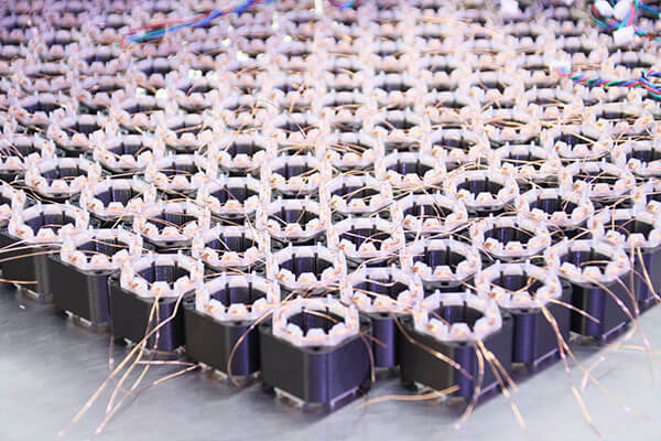
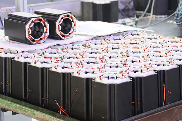
| Model | Step Angle | Phase | Shaft | Wires | Body Length | Current | Resistance | Inductance | Holding Torque | Leads No. | Rotor Inertia | Weight |
| (°) | / | / | / | (L)mm | A | Ω | mH | g.cm | No. | g.cm2 | Kg | |
| JK28HS32-0674 | 1.8 | 2 | Round | Directwires | 32 | 0.67 | 5.6 | 3.4 | 600 | 4 | 9 | 0.11 |
| JK28HS32-0956 | 1.8 | 2 | Round | Directwires | 32 | 0.95 | 2.8 | 0.8 | 430 | 6 | 9 | 0.11 |
| JK28HS45-0674 | 1.8 | 2 | Round | Directwires | 45 | 0.67 | 6.8 | 4.9 | 950 | 4 | 12 | 0.14 |
| JK28HS45-0956 | 1.8 | 2 | Round | Directwires | 45 | 0.95 | 3.4 | 1.2 | 750 | 6 | 12 | 0.14 |
| JK28HS51-0674 | 1.8 | 2 | Round | Directwires | 51 | 0.67 | 9.2 | 7.2 | 1200 | 4 | 18 | 0.2 |
| JK28HS51-0956 | 1.8 | 2 | Round | Directwires | 51 | 0.95 | 4.6 | 1.8 | 900 | 6 | 18 | 0.2 |
| Model | Step Angle | Phase | Shaft | Wires | Body Length | Shaft Dia | Shaft Length | Current | Resistance | Inductance | Holding Torque | Leads No. | Rotor Inertia | Weight |
| (°) | / | / | / | (L)mm | mm | mm | A | Ω | mH | N.cm | No. | g.cm2 | Kg | |
| JK42HS34-1334 | 1.8 | 2 | Round | Lead wire | 34 | 5 | 10 | 1.33 | 2.1 | 2.5 | 26 | 4 | 34 | 0.22 |
| JK42HS40-1204 | 1.8 | 2 | Round | Lead wire | 40 | 5 | 10 | 1.3 | 2.6 | 4.5 | 41 | 4 | 54 | 0.28 |
| JK42HS40-1704 | 1.8 | 2 | Round | Lead wire | 40 | 5 | 24 | 1.7 | 1.5 | 2.3 | 42 | 4 | 54 | 0.28 |
| JK42HS48-1684 | 1.8 | 2 | Round | Lead wire | 48 | 5 | 10 | 1.68 | 1.65 | 2.8 | 44 | 4 | 68 | 0.35 |
| JK42HS60-1704 | 1.8 | 2 | D-cut | Connector | 60 | 5 | 24 | 1.7 | 3 | 6.2 | 73 | 4 | 102 | 0.55 |
| Model | Step Angle | Phase | Shaft Type | Body Length | Shaft Dia | Shaft Length | Current | Resistance | Inductance | Holding Torque | Leads No. | Rotor Inertia | Weight |
| (°) | / | / | (L) mm | mm | mm | A | Ω | mH | Nm | No. | g.cm2 | Kg | |
| JK57HS41-2804 | 1.8 | 2 | Round | 41 | 8 | 14.5 | 2.8 | 0.7 | 1.4 | 0.55 | 4 | 150 | 0.47 |
| JK57HS51-2804 | 1.8 | 2 | Round | 51 | 8 | 21 | 2.8 | 0.83 | 2.2 | 1.01 | 4 | 230 | 0.59 |
| JK57HS56-2804 | 1.8 | 2 | Round | 56 | 8 | 14.5 | 2.8 | 0.9 | 2.5 | 1.26 | 4 | 280 | 0.68 |
| JK57HS76-2804 | 1.8 | 2 | Round | 76 | 8 | 14.5 | 2.8 | 1.1 | 3.6 | 1.89 | 4 | 440 | 1.1 |
| JK57HS82-3004 | 1.8 | 2 | Round | 82 | 8 | 21 | 3.0 | 1.2 | 4.0 | 2.1 | 4 | 600 | 1.2 |
| JK57HS100-3004 | 1.8 | 2 | Round | 100 | 8 | 14.5 | 3.0 | 0.75 | 3.0 | 3.0 | 4 | 700 | 1.3 |
| JK57HS112-3004 | 1.8 | 2 | Round | 112 | 8 | 21 | 3.0 | 1.6 | 7.5 | 3.0 | 4 | 800 | 1.4 |
| JK57HS112-4204 | 1.8 | 2 | Round | 112 | 8 | 21 | 4.2 | 0.9 | 3.8 | 3.1 | 4 | 800 | 1.4 |
| Gearbox Model | NMRV30 | ||||||||||
| Motor Power /KW | ≤0.18 | ||||||||||
| Gear Ratio | 5 | 7.5 | 10 | 15 | 20 | 25 | 30 | 40 | 50 | 60 | 80 |
| Effiency % | 40-70 | ||||||||||
| Suitable Motor Max Size /mm | 63 | ||||||||||
| Torque /N.m | 24 | ||||||||||
| Output Hole Dimension /mm | 14 | ||||||||||
| Input Hole Dimension /mm | 9/11 | ||||||||||
| Gearbox Weight /Kg | 1.2 | ||||||||||
| Model | Step Angle | Phase | Shaft Type | Wires | Body Length | Current | Resistance | Inductance | Holding Torque | Leads No. | Rotor Inertia | Weight |
| (°) | / | / | / | (L)mm | A | Ω | mH | N.m | No. | g.cm2 | Kg | |
| JK60HS56-2804 | 1.8 | 2 | Round | Direct wire | 56 | 2.8 | 0.9 | 3.6 | 1.65 | 4 | 300 | 0.77 |
| JK60HS67-2804 | 1.8 | 2 | Round | Direct wire | 67 | 2.8 | 1.2 | 4.6 | 2.1 | 4 | 570 | 1.2 |
| JK60HS88-2804 | 1.8 | 2 | Round | Direct wire | 88 | 2.8 | 1.5 | 6.8 | 3.1 | 4 | 840 | 1.4 |
| JK60HS100-2804 | 1.8 | 2 | Round | Direct wire | 100 | 2.8 | 1.6 | 6.4 | 4 | 4 | 980 | 1100 |
| JK60HS111-2804 | 1.8 | 2 | Round | Direct wire | 111 | 2.8 | 2.2 | 8.3 | 4.5 | 4 | 1120 | 1200 |
| Gearbox Model | NMRV30 | ||||||||||
| Motor Power /KW | ≤0.18 | ||||||||||
| Gear Ratio | 5 | 7.5 | 10 | 15 | 20 | 25 | 30 | 40 | 50 | 60 | 80 |
| Effiency % | 40-70 | ||||||||||
| Suitable Motor Max Size /mm | 63 | ||||||||||
| Torque /N.m | 24 | ||||||||||
| Output Hole Dimension /mm | 14 | ||||||||||
| Input Hole Dimension /mm | 9/11 | ||||||||||
| Gearbox Weight /Kg | 1.2 | ||||||||||
| Model | Step Angle | Phase | Shaft Type | Wires | Body Length | Current | Resistance | Inductance | Holding Torque | Leads No. | Rotor Inertia | Weight |
| (°) | / | / | / | (L)mm | A | Ω | mH | Nm | No. | g.cm2 | Kg | |
| JK86HS78-6004 | 1.8 | 2 | Key | Direct wire | 78 | 6.0 | 0.37 | 3.4 | 4.6 | 4 | 1400 | 2.3 |
| JK86HS115-6004 | 1.8 | 2 | Key | Direct wire | 115 | 6.0 | 0.6 | 6.5 | 8.7 | 4 | 2700 | 3.8 |
| JK86HS126-6004 | 1.8 | 2 | Key | Direct wire | 126 | 6.0 | 0.58 | 6.5 | 9.5 | 4 | 3200 | 4.5 |
| JK86HS155-6004 | 1.8 | 2 | Key | Direct wire | 155 | 6.0 | 0.68 | 9.0 | 13.0 | 4 | 4000 | 5.4 |
| Gearbox Model | NMRV40 | |||||||||||
| Motor Power /KW | ≤0.37 | |||||||||||
| Gear Ratio | 5 | 7.5 | 10 | 15 | 20 | 25 | 30 | 40 | 50 | 60 | 80 | 100 |
| Effiency % | 35-70 | |||||||||||
| Suitable Motor Max Size /mm | 71 | |||||||||||
| Torque /N.m | 52 | |||||||||||
| Output Hole Dimension /mm | 18 | |||||||||||
| Input Hole Dimension /mm | 11/14 | |||||||||||
| Gearbox Weight /Kg | 2.3 | |||||||||||
A stepper motor cannot function like a traditional DC motor because it requires a dedicated stepper driver that sends pulse signals to control each step of rotation. However, with the correct controller and driver, it can achieve precise speed and position control in many automation systems.
Stepper motors can be paired with different gearbox types depending on the application, including:
Planetary gearboxes for high precision motion control
Spur gearboxes for economical speed reduction
Worm gearboxes for high torque and self-locking
Helical gearboxes for smooth and quiet performance
The four common types of gearboxes used in motors include:
Planetary gearbox – high torque density and precision
Spur gearbox – simple structure and cost-effective
Worm gearbox – high reduction ratio and self-locking capability
Helical gearbox – smooth operation and high efficiency
Geared motors are widely used in industries where high torque and controlled speed are required. Common applications include:
Robotics and automation systems
Conveyor equipment
Medical instruments
Packaging and labeling machines
CNC machinery
AGV and mobile robots
Higher torque output
Lower operating speed with better control
Improved efficiency in load-driven applications
Compact power transmission solution
Additional mechanical complexity
Possible backlash in the gearbox
Increased cost compared to standard motors
Gear wear over long-term operation
Standard stepper motors typically operate without gears, but they can be paired with external gearboxes to form a geared stepper motor. Adding gears helps increase torque output, improve positioning accuracy, and reduce the motor’s output speed for applications requiring controlled and powerful movement.
A worm geared stepper motor integrates a worm gearbox that significantly increases torque while offering self-locking capability, preventing backdriving and maintaining load position even when power is off.
© COPYRIGHT 2025 CHANGZHOU JKONGMOTOR CO.,LTD ALL RIGHTS RESERVED.