A stepper motor converts electrical pulses into precise incremental motion through controlled coil energizing for accurate positioning, and OEM/ODM customized stepper motors offer tailored designs (e.g., shafts, housings, gearboxes, encoders) that optimize performance, integration, and reliability for specific industrial applications.
A stepper motor works by converting electrical pulses into precise, incremental mechanical movement. Instead of spinning freely like a standard DC motor, it rotates in fixed step angles, moving one “step” at a time. Each step is created when the motor’s internal coils are energized in a controlled sequence, producing a rotating magnetic field that pulls the rotor into the next stable position.
This simple concept is the reason stepper motors are widely used in automation, CNC machines, 3D printers, medical devices, packaging systems, and precision positioning applications.
Stepper Motor Working Principle (Short and Accurate)
The working principle of a stepper motor is based on electromagnetism and sequential coil energizing:
The motor contains multiple stator windings (coils) arranged in phases.
The controller sends electrical pulses to these coils in a specific order.
Each pulse creates a magnetic field that attracts the rotor.
The rotor aligns with the energized stator pole.
When the next coil is energized, the rotor moves to the next position.
Every pulse equals a known mechanical movement, allowing stepper motors to deliver repeatable positioning without requiring a feedback sensor in many applications.
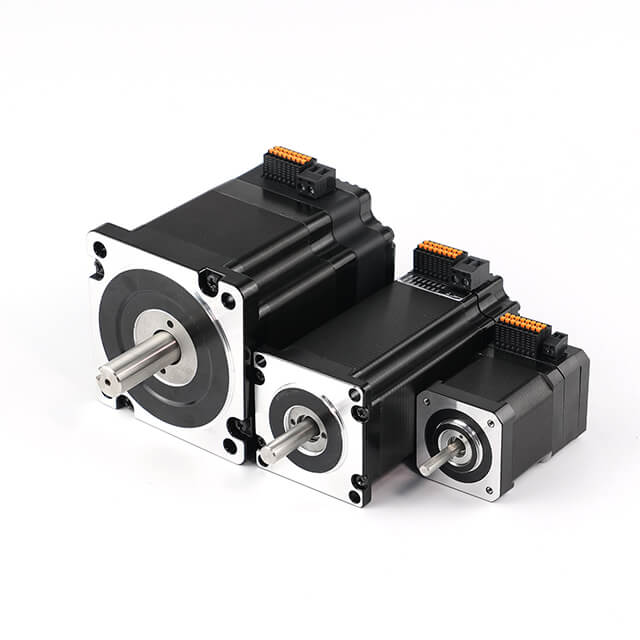
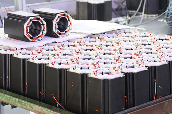
Customized Stepper Motor Types for Heavy Load Industry Applications
Customized Stepper Motor Service & Integration for Heavy Load Industry
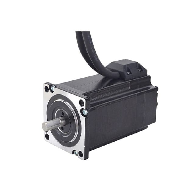
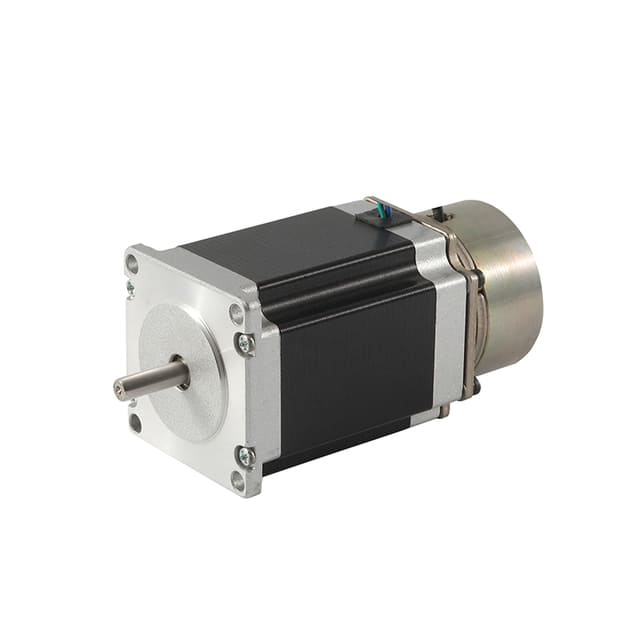
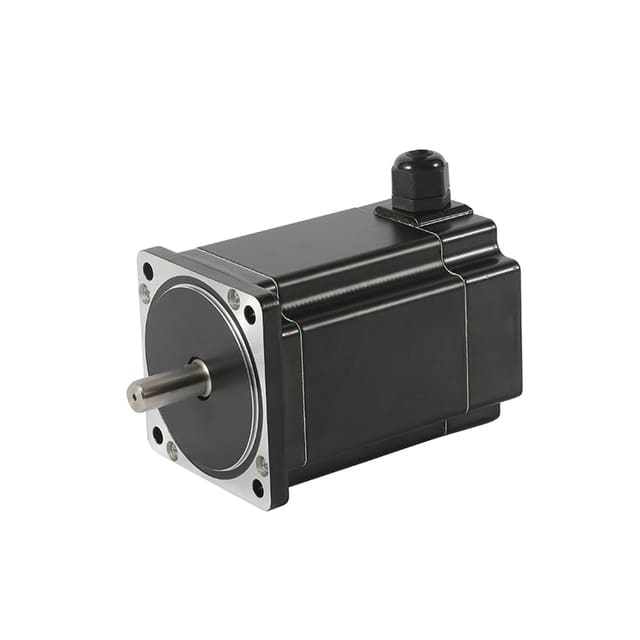
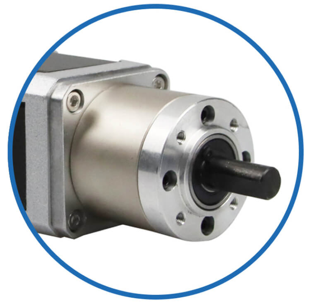
As a professional brushless dc motor manufacturer with 13 years in china, Jkongmotor offer various bldc motors with customized requirements, including 33 42 57 60 80 86 110 130mm, additionally, gearboxes, brakes, encoders, brushless motor drivers and integrated drivers are optional.
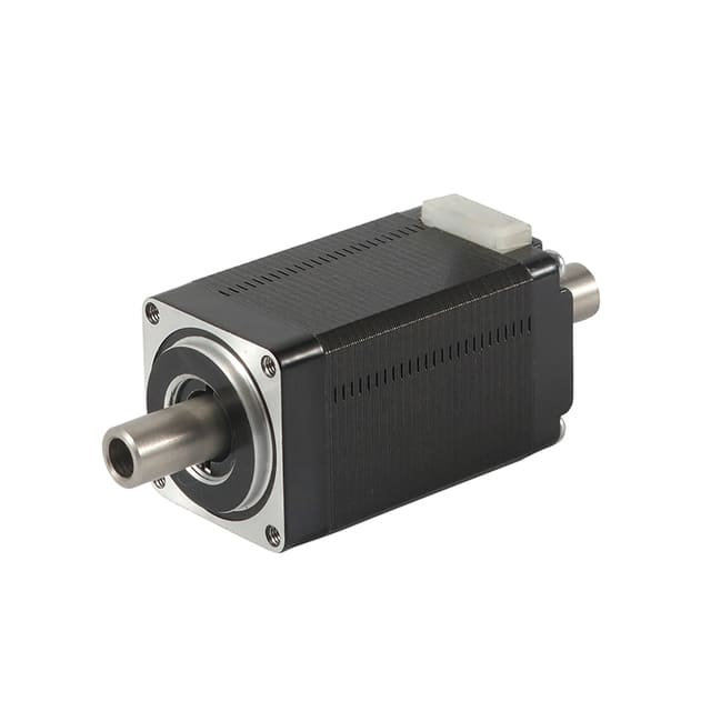
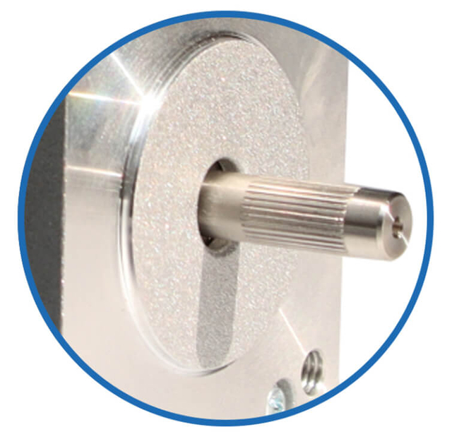
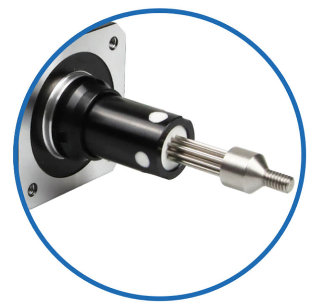
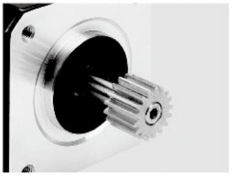
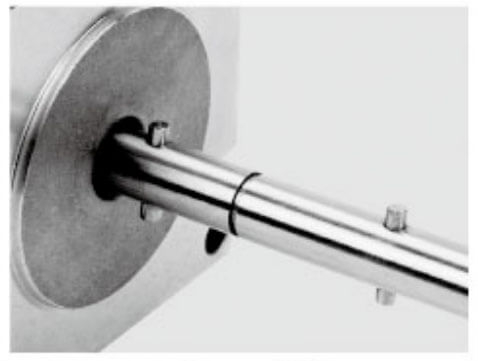
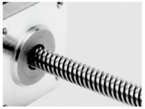
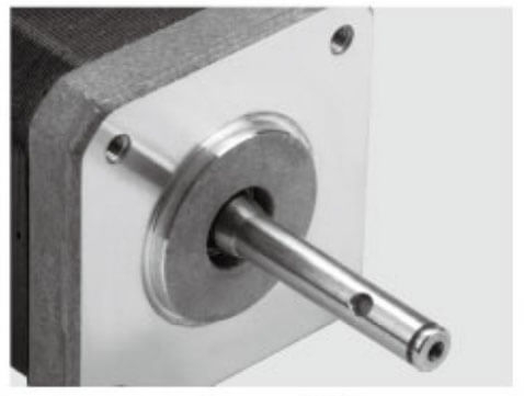
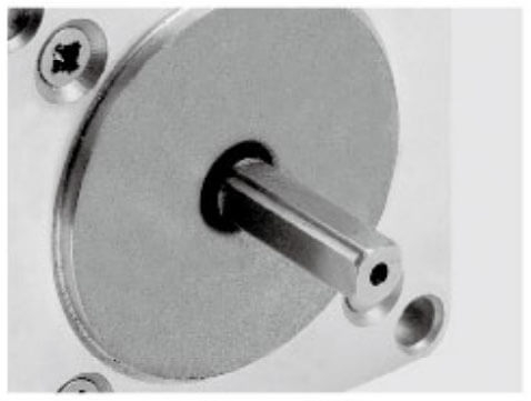
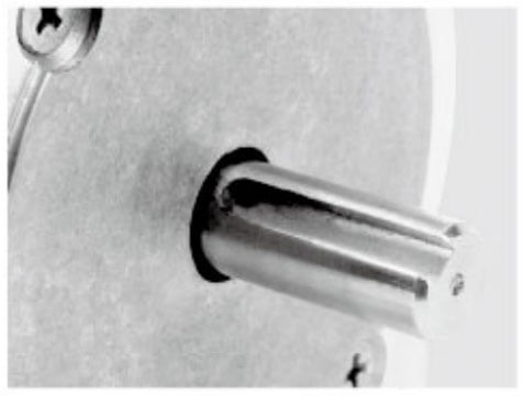
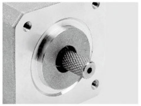
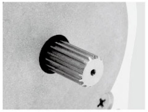
Jkongmotor offer many different shaft options for your motor as well as customizable shaft lengths to make the motor fit your application seamlessly.
Key Components Inside a Stepper Motor
A stepper motor is built with several core parts that work together to create precise step-by-step rotation. Below are the most important internal components:
1) Stator (Stationary Core)
The stator is the fixed outer part of the motor. It contains multiple electromagnetic coils (windings) arranged in phases. When current flows through these windings, the stator generates a magnetic field that controls the rotor’s movement.
2) Rotor (Rotating Element)
The rotor is the moving shaft component that turns in response to the stator’s magnetic field. Depending on the motor design, the rotor can be:
Permanent Magnet Rotor (uses magnets for stronger alignment)
Soft Iron Toothed Rotor (relies on magnetic reluctance)
Hybrid Rotor (combines magnets + teeth for higher accuracy and torque)
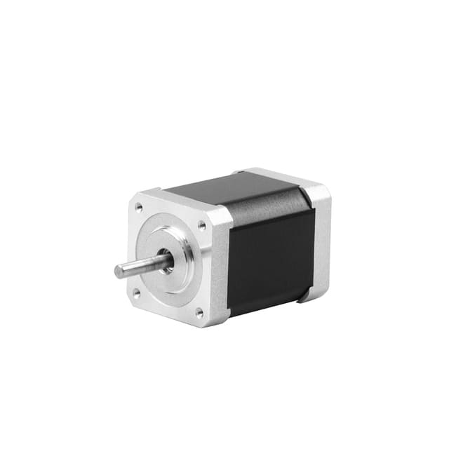
3) Shaft
The shaft is connected to the rotor and transfers the motor’s rotational movement to the external load, such as a pulley, lead screw, gear, or coupling.
4) Bearings
High-quality bearings support the shaft and allow smooth rotation while reducing friction, vibration, and mechanical wear.
5) Windings (Coils)
The motor’s windings are copper coils that become electromagnets when energized. The controlled energizing of these windings is what creates the stepping motion.
6) Phases
Stepper motors are divided into phases (commonly 2-phase or 4-phase). The number of phases affects how the motor is driven, including step resolution and torque output.
7) Teeth (Pole Structure)
Many stepper motors, especially hybrid stepper motors, use fine teeth on the rotor and stator poles. These teeth improve:
Positioning accuracy
Torque stability
Step resolution
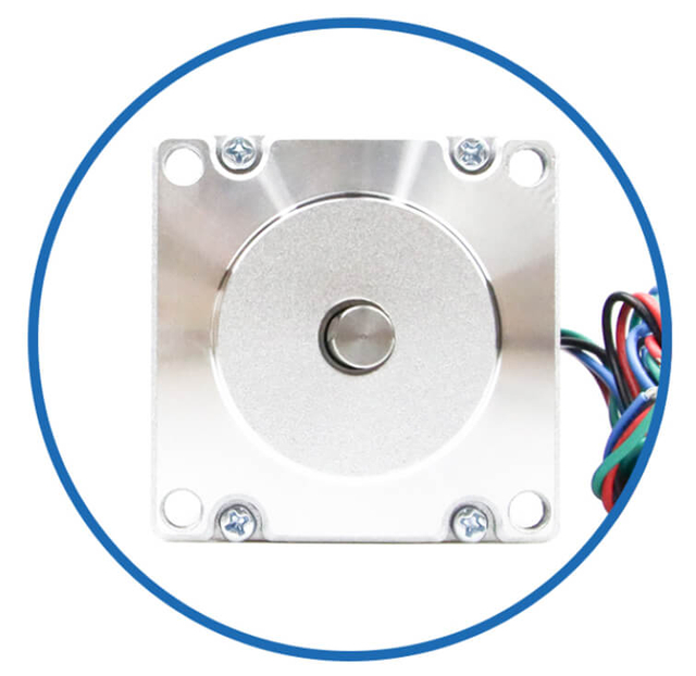
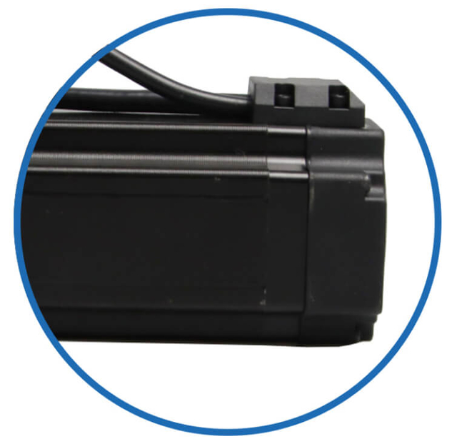
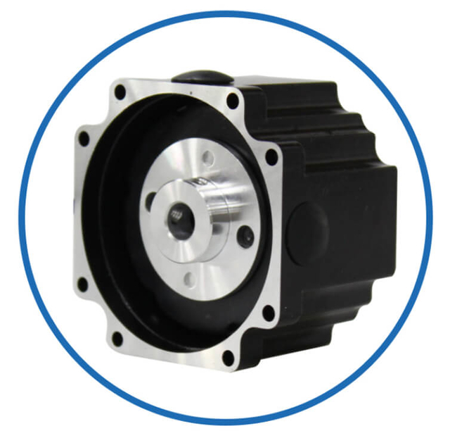
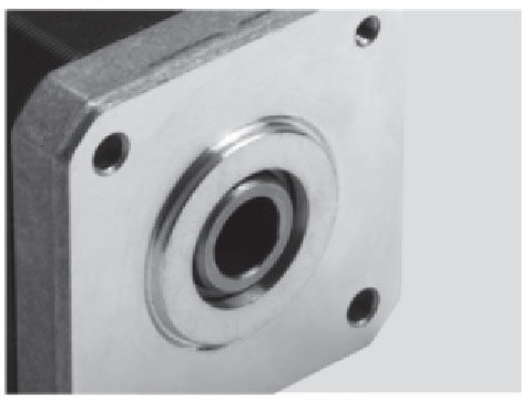
8) Frame and Housing
The motor’s frame holds all components in alignment and provides structural strength. It also helps with heat dissipation, which is important because stepper motors often run under continuous current.
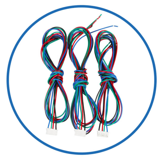
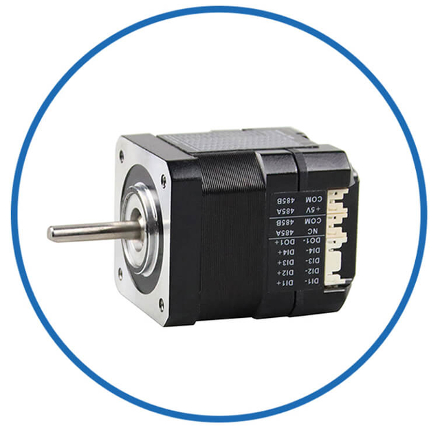
9) Connector and Lead Wires
Stepper motors use external lead wires (commonly 4, 6, or 8 wires) to connect the stator windings to the stepper driver, enabling different wiring modes like bipolar or unipolar configurations.
Each of these components plays a direct role in delivering accurate, repeatable motion, which is why stepper motors are widely used in automation, CNC machines, robotics, and precision positioning systems.
A stepper motor moves by turning electrical pulses into controlled mechanical steps. Instead of spinning continuously, it rotates in small, fixed increments, allowing precise positioning.
Here is the step-by-step motion process:
1) The Controller Sends a Pulse
A motion controller (PLC, CNC board, or microcontroller) sends a STEP signal to the stepper driver.
Each pulse represents one step (or one microstep if microstepping is enabled).
2) The Driver Energizes the Stator Coils
The stepper driver supplies current to the motor’s stator windings in a specific pattern. This creates a strong electromagnetic field inside the motor.
3) A Magnetic Pole Is Formed
When a coil is energized, it becomes a magnetic pole (north or south). The motor now has an active magnetic “target” position.
4) The Rotor Aligns to the Magnetic Field
The rotor (magnet or toothed rotor) is pulled into alignment with the energized stator pole.
This alignment is the motor’s stable step position.
5) The Next Pulse Shifts the Magnetic Field
When the next pulse arrives, the driver energizes the next coil (or coil combination). The magnetic field shifts forward by one step.
6) The Rotor Moves to the Next Step
The rotor follows the shifting magnetic field and rotates to the next stable position.
This produces a precise step movement.
7) Continuous Pulses Create Continuous Rotation
By sending pulses continuously, the motor keeps stepping forward and appears to rotate smoothly.
What Pulse Control Determines
Pulse count = position (how far it moves)
Pulse frequency = speed (how fast it moves)
Phase order = direction (forward or reverse)
This is why stepper motors are widely used for accurate, repeatable motion control in applications like CNC machines, 3D printers, robotics, and automated positioning systems.
OEM Stepper Motor Step Sequences (Full-Step, Half-Step, Microstepping)
The way coils are energized determines motion quality, torque, and smoothness.
Full-Step Drive
Full-step driving moves the rotor in standard step increments.
Advantages
Best for
Half-Step Drive
Half-step drive alternates between energizing one phase and two phases, creating smaller steps.
Advantages
Best for
Microstepping
Microstepping divides each full step into many smaller micro-steps using controlled current waveforms.
Advantages
Best for
Microstepping improves smoothness but may reduce usable torque per microstep depending on load and tuning.
How Stepper Motor Speed Works (Simple Explanation)
A stepper motor’s speed is controlled by the frequency of input pulses sent from the controller to the driver. Since a stepper motor moves in fixed increments, the faster the pulses arrive, the faster the motor rotates.
1) Pulse Frequency Controls Speed
In simple terms: more pulses per second = more steps per second = higher speed.
2) Step Angle Determines How Many Pulses per Revolution
The motor’s step angle defines how many steps are needed to complete one full turn.
Example:
1.8° step angle = 200 steps per revolution
If the controller sends 200 pulses, the motor completes 1 full revolution
So, speed depends on how quickly those pulses are delivered.
3) Microstepping Changes Speed Resolution
With microstepping, one full step is divided into smaller steps (microsteps), such as:
1/2 step
1/4 step
1/8 step
1/16 step
This makes motion smoother, but it also means more pulses are needed per revolution, which affects how speed is calculated.
4) Acceleration Matters
Stepper motors cannot instantly jump from low speed to high speed under load. If pulse frequency increases too quickly, the motor may:
That’s why stepper systems use acceleration and deceleration ramps for stable motion.
5) Load and Torque Limit Maximum Speed
As speed increases, available torque decreases. Heavy loads, high friction, or poor tuning can reduce the motor’s achievable speed and cause missed steps.
In summary: a stepper motor’s speed is determined by how fast step pulses are sent, while real-world performance depends on step angle, microstepping settings, acceleration profile, and load torque.
A stepper motor’s direction is controlled by the order in which the stator coils (phases) are energized. The motor rotates forward or backward depending on the phase sequence generated by the stepper driver.
1) Coil Energizing Sequence Controls Rotation
Inside the motor, the driver switches current through the coils in a specific pattern:
So, changing direction is simply a matter of reversing the coil activation sequence.
2) DIR Signal Sets the Direction
Most stepper drivers use two control inputs:
When the controller changes the DIR signal, the driver reverses the phase sequence, and the motor immediately changes rotation direction.
3) Direction Is Independent of Speed
The motor can rotate forward or backward at any speed as long as:
In summary: a stepper motor changes direction by reversing the energizing order of its coils, which reverses the rotating magnetic field and forces the rotor to step in the opposite direction.
One of the key advantages of a stepper motor is its ability to hold a fixed position without continuous rotation. This is due to holding torque, which allows the motor to “lock” the rotor in place when the coils are energized, even if no movement is commanded.
1) What Is Holding Torque?
Holding torque is the amount of rotational force the motor can resist while stationary with the windings powered. It occurs because the energized stator creates a magnetic field that keeps the rotor aligned with the current step.
The rotor is magnetically “locked” in its position
No additional mechanical brakes are needed
The torque resists external forces that try to move the shaft
2) Why Stepper Motors Hold Position
Unlike DC motors, stepper motors do not rely on momentum or friction. When current flows through the windings:
This makes them ideal for applications where precise positioning and stability are critical.
3) Factors Affecting Holding Torque
The actual holding torque depends on several factors:
Motor size – larger motors generally produce higher torque
Current level – higher winding current increases the magnetic pull
Motor type – hybrid stepper motors typically have stronger holding torque than permanent magnet types
Temperature – excessive heat can reduce torque output
4) Applications of Holding Torque
Holding torque allows stepper motors to maintain position without extra devices:
Vertical axis machinery – prevents load from falling
CNC and 3D printer axes – keeps tool or platform precisely in place
Indexing tables and packaging systems – locks products during processing
Robotic arms – maintains joint position under load
In summary: stepper motors can “lock” in place because the energized stator coils create a magnetic holding force, which aligns and holds the rotor at a precise step. This unique feature provides stability and repeatable positioning in many automation and precision applications.
Why Stepper Motors Are So Precise Without Feedback
Stepper motors are known for their high precision and repeatability, even in open-loop systems that do not use position feedback. This precision comes from the motor’s inherent step-based operation, where each input pulse corresponds to a fixed angular rotation.
1) Pulse-Counting Determines Position
Every pulse sent to a stepper motor moves the rotor by a specific step angle:
By counting the number of pulses, the controller “knows” the exact position of the rotor without needing a sensor. This makes the system highly predictable and repeatable.
2) Fixed Step Movement
Because the rotor moves in discrete steps, it can accurately reach any position as long as:
The motor does not skip steps
The load is within the torque capacity
The acceleration and deceleration are properly managed
This step-based motion is why stepper motors excel in applications that require precise indexing, alignment, and repeatable motion.
3) No Encoder Needed for Many Applications
Unlike DC motors, which rely on feedback systems to correct position errors, stepper motors can operate reliably in open-loop systems:
Reduces cost and complexity
Simplifies control architecture
Provides reliable positioning for 3D printers, CNC machines, and automation systems
4) Factors That May Require Feedback
While stepper motors are precise without feedback, certain high-demand systems may still use encoders to:
Detect missed steps under heavy load
Improve synchronization in multi-axis systems
Optimize torque and acceleration for complex motion profiles
In summary: stepper motors achieve high precision without feedback because each electrical pulse moves the rotor a fixed, known angle, allowing accurate positioning purely through pulse counting and controlled energizing of phases. This makes them ideal for repeatable, predictable motion control in a wide range of industrial and automation applications.
Stepper Motor Types and How They Differ
Stepper motors come in several types, each designed to optimize torque, precision, and efficiency for specific applications. Understanding the differences helps engineers select the right motor for their system.
1) Permanent Magnet (PM) Stepper Motor
Design:
Uses a permanent magnet rotor and a simple stator with multiple windings.
Characteristics:
Moderate torque at low speeds
Simple design and affordable
Step resolution is usually lower than hybrid types
Best for:
2) Variable Reluctance (VR) Stepper Motor
Design:
Rotor is made of soft iron with teeth, no magnets. Stator generates a magnetic field that aligns the rotor to the nearest low-reluctance path.
Characteristics:
Fast response and low rotor inertia
Smooth motion at moderate speeds
Requires precise driver control
Best for:
Applications needing rapid stepping
Low-mass positioning tasks
Simple automated machinery
Design:
Combines permanent magnets with a toothed rotor, creating a high-precision hybrid structure.
Characteristics:
High torque density
High step resolution and accuracy
Smooth operation at low and moderate speeds
Most widely used stepper motor type
Best for:
4) Unipolar vs. Bipolar Configuration
Stepper motors can also differ in wiring style:
Unipolar: Current flows in one direction per coil, simpler driver, slightly lower torque
Bipolar: Current reverses in coils, higher torque, requires more complex driver
Impact: Wiring configuration affects torque output, driver complexity, and microstepping performance.
In summary: the main stepper motor types—Permanent Magnet, Variable Reluctance, and Hybrid—differ in rotor design, torque, speed, and precision. Hybrid stepper motors dominate precision applications, while PM and VR types are suitable for lighter, low-cost tasks. Proper selection ensures optimal performance, efficiency, and reliability in any motion control system.
Stepper Motor vs DC Motor (Short Comparison)
A stepper motor is optimized for precision, while a DC motor is optimized for continuous rotation.
Stepper motor
DC motor
Stepper motors and DC motors serve different purposes in motion control systems. Here’s a concise comparison highlighting their key differences:
| Feature | Stepper Motor | DC Motor |
| Motion Type | Moves in discrete steps | Rotates continuously |
| Position Control | Can maintain exact position without feedback | Requires encoder or sensor for precise positioning |
| Torque | Strong holding torque at standstill | Torque is proportional to current; no natural holding torque |
| Speed Control | Speed depends on pulse frequency | Speed controlled via voltage or PWM |
| Precision | High repeatability; step angle defines accuracy | Precision requires closed-loop control |
| Applications | CNC machines, 3D printers, robotics, automated positioning | Fans, pumps, conveyors, general rotation applications |
Summary: Stepper motors excel in precise, repeatable positioning, while DC motors are better suited for continuous rotation and variable-speed applications. The choice depends on whether the system prioritizes position accuracy or continuous motion.
When positioning accuracy is required without complex control loops, stepper motors remain a highly efficient choice.
Stepper motors are widely used wherever precise, repeatable, and controlled motion is required. Their ability to move in fixed steps without needing continuous feedback makes them ideal for many industrial, commercial, and consumer applications.
1) 3D Printers
Control the X, Y, and Z axes with high precision
Move the extruder and print bed accurately
Provide repeatable layer positioning for consistent prints
2) CNC Machines
Drive spindles, tool heads, and linear axes
Ensure exact cutting, drilling, and milling positions
Enable complex automated machining with minimal error
3) Laser Engravers and Cutters
Precisely guide the laser along patterns
Allow fine detail work with repeatable positioning
Integrate easily with computer-controlled designs
4) Robotics and Automated Systems
Control robotic arms and joints for repeatable motion
Perform pick-and-place tasks in assembly lines
Provide precise rotational or linear actuation
5) Camera Sliders and Gimbals
Smoothly move camera platforms for video or photography
Enable time-lapse sequences with accurate step increments
Maintain stable angles and positions during filming
6) Medical Devices
Drive pumps, infusion systems, and surgical tools
Ensure accurate dosing and controlled movement
Offer reliability in sensitive healthcare applications
7) Packaging Equipment
Operate indexing tables, feeders, and label applicators
Maintain repeatable motion for production lines
Improve efficiency and accuracy in automated packaging
8) Textile Machinery
Control pattern repeat, knitting, and weaving
Provide precise movement of threads or needles
Reduce errors in complex fabric production
9) Automated Valves and Actuators
Open and close valves with exact timing
Control fluid or gas flow in industrial systems
Maintain repeatable operation without additional sensors
Summary: Stepper motors are used anywhere precision, repeatability, and controlled motion are essential. Their combination of step-based rotation, holding torque, and open-loop accuracy makes them indispensable in automation, manufacturing, robotics, and precision devices.
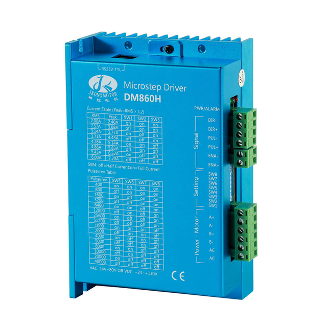
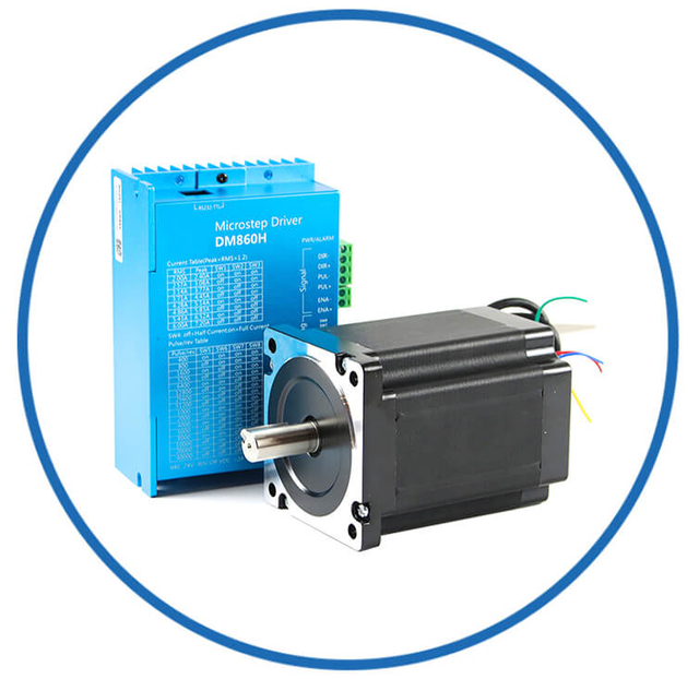
What Controls a Stepper Motor? (Driver and Controller Basics)
A stepper motor requires a stepper driver, and usually a controller such as:
The driver manages coil current and switching patterns. The controller sends two primary signals:
This setup makes stepper motors easy to integrate into modern automation systems.
Even though stepper motors are precise, performance depends on proper setup.
1) Missed Steps
Occurs when the motor cannot generate enough torque to follow the commanded pulses.
Common causes:
Load too heavy
Acceleration too fast
Driver current too low
2) Vibration and Noise
Often happens at certain speeds due to resonance.
Solutions include:
3) Overheating
Stepper motors may run warm because they often hold current even at standstill.
Reducing current at idle can improve thermal performance.
Short Summary: How Does a Stepper Motor Work?
A stepper motor works by energizing internal coils in a timed sequence, creating a rotating magnetic field that moves the rotor in precise steps. Each pulse equals a fixed amount of movement, allowing accurate control of position, speed, and direction. This makes stepper motors ideal for applications requiring repeatable motion, stable holding torque, and reliable open-loop positioning.
FAQs — Stepper Motor & OEM/ODM Customized
What is a stepper motor and how does it work?
A stepper motor converts electrical pulses into precise, incremental mechanical motion, rotating in fixed “steps” as coils are energized in sequence.
What makes a stepper motor especially suitable for precision positioning?
Each pulse corresponds to a fixed mechanical movement, enabling exact control over position without feedback in many open-loop systems.
What components inside a stepper motor enable step-by-step rotation?
A stepper motor has a stator with multiple coils and a rotor whose alignment shifts in precise steps according to magnetic fields created by coil energizing.
How does the controller affect a stepper motor’s movement?
The controller sends electrical pulses that dictate position (pulse count), speed (pulse frequency), and direction (phase order).
What are the common step sequences used in stepper motor control?
Full-step, half-step, and microstepping sequences determine motion resolution, smoothness, and torque.
Can a stepper motor operate without a feedback sensor?
Yes — many stepper motors operate in open-loop mode with no need for external position feedback as long as the load is within specification.
What industries use stepper motors for motion control?
Stepper motors are widely used in CNC machines, 3D printers, automation systems, robotics, medical devices, and packaging equipment.
What determines a stepper motor’s speed and rotational direction?
Speed is set by the frequency of pulses, and direction is controlled by the energizing order of stator coils.
Why are stepper motors considered robust and reliable for repetitive motion?
Their simple architecture and pulse-based motion control provide repeatable, stable motion with fewer failure points.
How does microstepping improve stepper motor performance?
Microstepping divides full steps into smaller increments for smoother motion and higher resolution at reduced torque.
What OEM/ODM customizations are available for stepper motors?
OEM/ODM options include custom shaft designs, lead wires, connectors, mounting brackets, housings, and value-add components such as encoders and gearboxes.
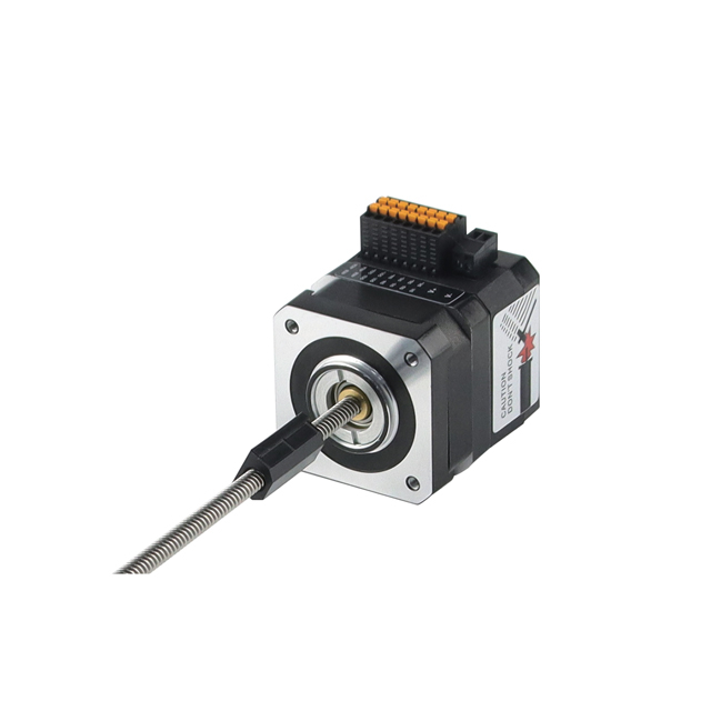
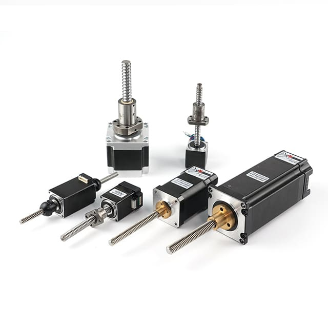
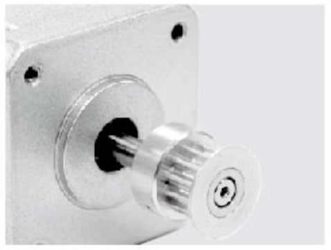
Can lead screws or pulleys be integrated into a customized stepper motor?
Yes — customized lead screws, pulleys, and gear outputs can be integrated as part of tailored motor services.
What does “OEM/ODM stepper motor shaft customization” include?
Customization can involve unique shaft lengths, hollow shafts, pulleys, gears, shaft flats, and drilling details to fit specific applications.
Why might a company choose a customized stepper motor over a standard one?
Customized stepper motors ensure precise fit, optimized performance, reduced assembly complexity, and improved integration into machinery.
How does OEM/ODM tailored design improve system reliability?
Custom engineering aligns motor specifications with application requirements, reducing mechanical stress and vibration, which enhances reliability.
Can customizing a stepper motor reduce total system cost?
Yes — while unit cost may be higher, customization often lowers lifecycle costs by minimizing rework, extra components, and maintenance demands.
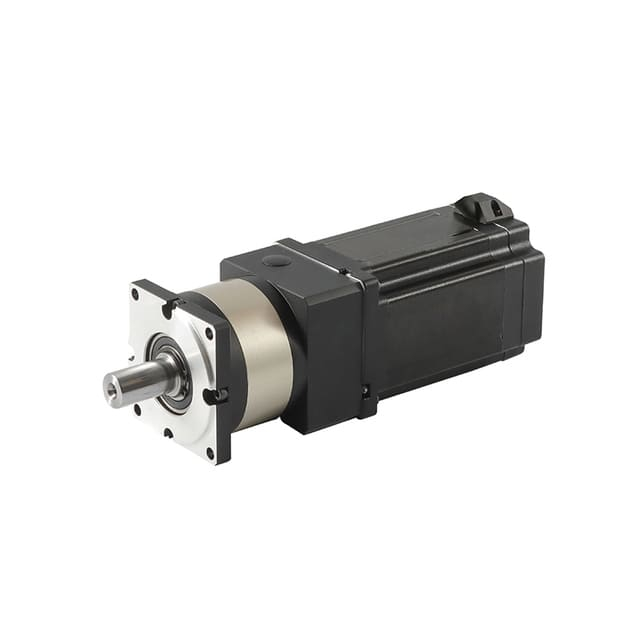
Do OEM/ODM services extend to integrated drivers for stepper motors?
Yes — integrated drivers, encoders, gearboxes, and other components can be combined with stepper motors for turnkey solutions.
How important are certifications for customized stepper motors?
Certifications like CE, RoHS, and ISO indicate quality control standards and compliance for industrial customers.
Can waterproof or ruggedized stepper motors be customized?
Yes — IP-rated, waterproof, or dust-resistant housings are available for special environment requirements.
What value does OEM/ODM customization add for long-term supply and product continuity?
Consistent design platforms and dedicated manufacturing processes support long-term sourcing and stable performance over product lifecycles.