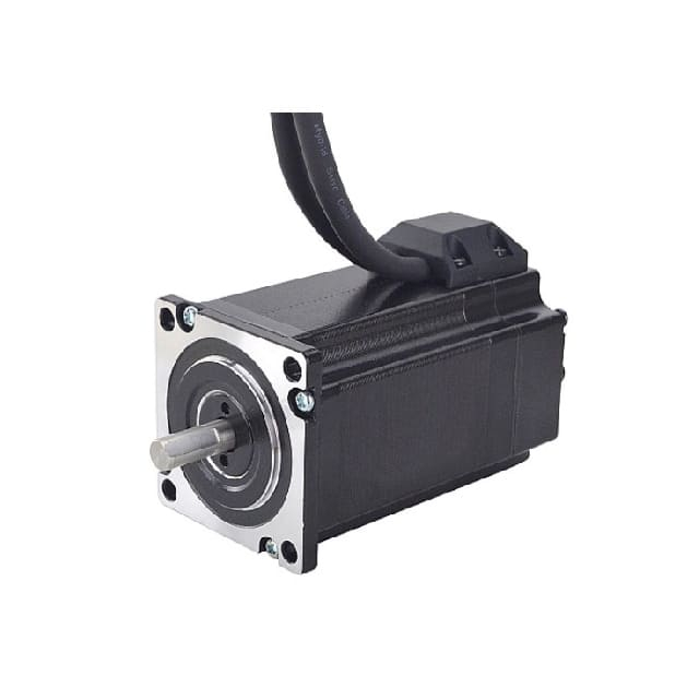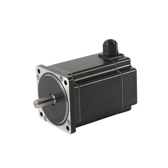
High-precision stepper motors can have 2 to 8 wires depending on winding design, and JKongmotor’s OEM-ODM customized service supports tailored wiring, connectors, sizes, encoders, gearboxes, integrated drivers, environmental protection, and factory-level engineering to meet specific industrial motion control needs.
Stepper motors are widely used in CNC machines, 3D printers, robotics, medical devices, and industrial automation because they provide accurate motion control without needing complex feedback systems in many applications. One of the most common questions engineers and buyers ask is: how many wires does a stepper motor have?
The answer depends on the motor’s internal winding configuration and how it is designed to be driven. In real-world projects, stepper motors typically come in 2-wire, 4-wire, 5-wire, 6-wire, or 8-wire versions. Each wiring type impacts performance, driver compatibility, torque characteristics, and ease of wiring.
Below, we explain each stepper motor wire count in detail, including what it means, how it works in practice, and how to identify it quickly.
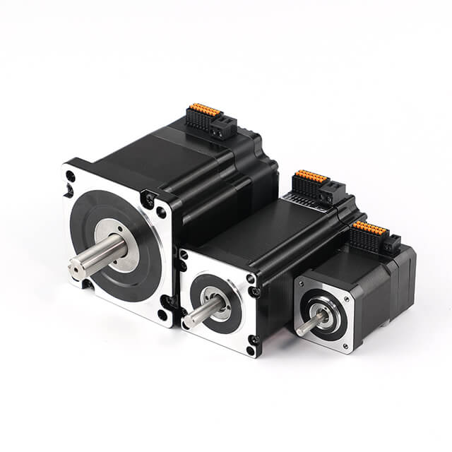
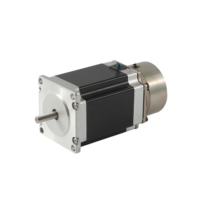
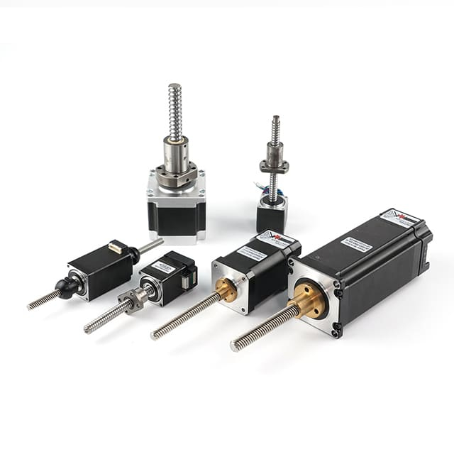
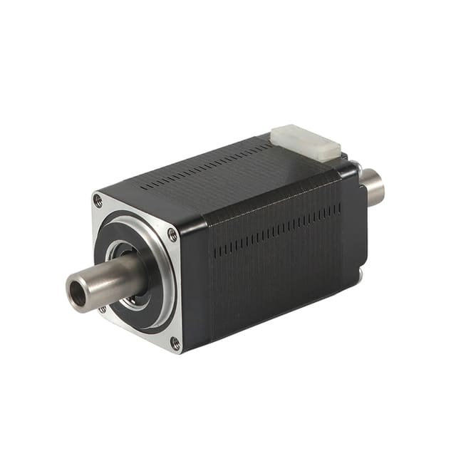
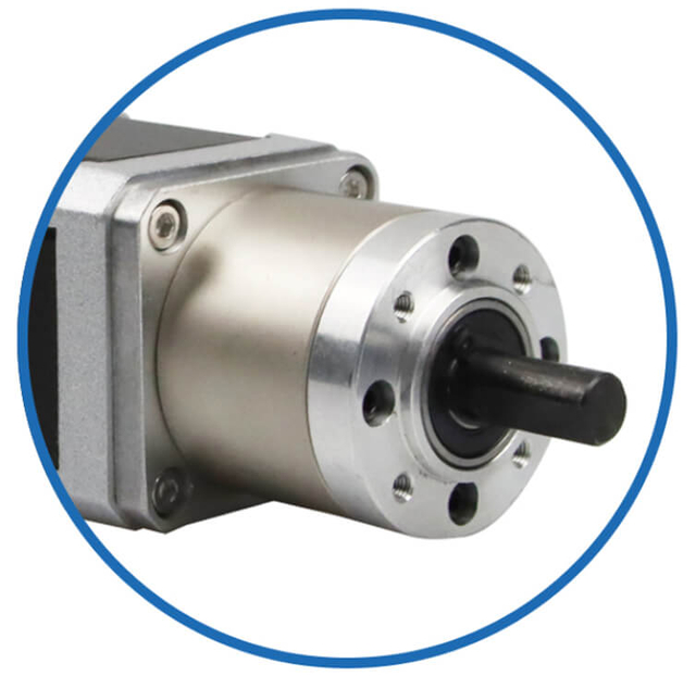
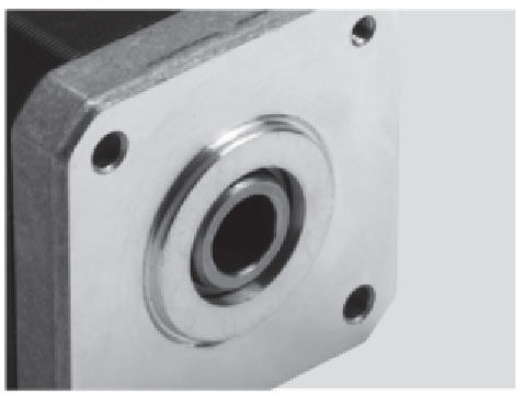
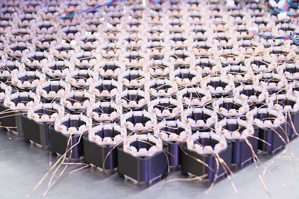
Customized Stepper Motor Types for Heavy Load Industry Applications
Customized Stepper Motor Service & Integration for Heavy Load Industry
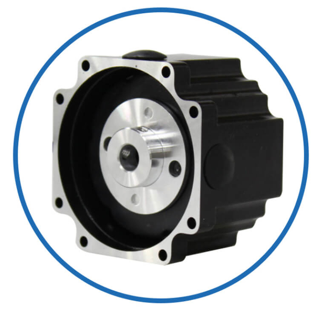
As a professional brushless dc motor manufacturer with 13 years in china, Jkongmotor offer various bldc motors with customized requirements, including 33 42 57 60 80 86 110 130mm, additionally, gearboxes, brakes, encoders, brushless motor drivers and integrated drivers are optional.
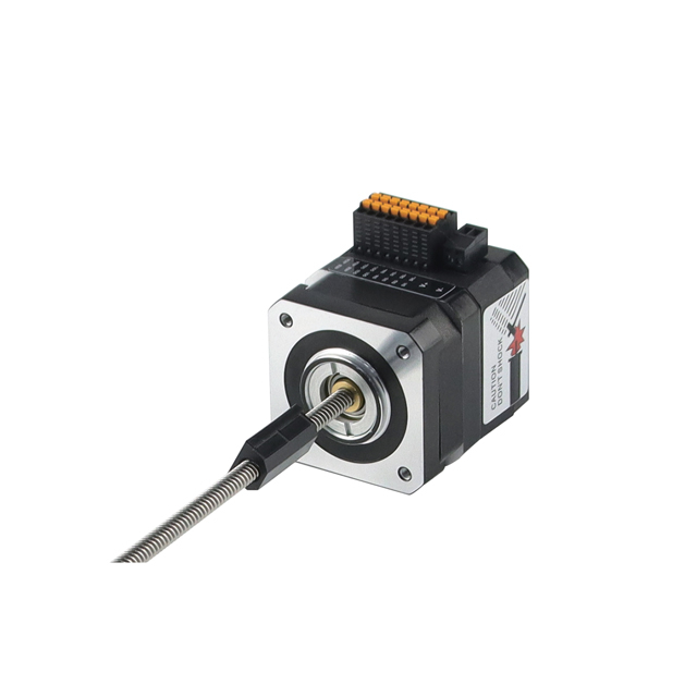
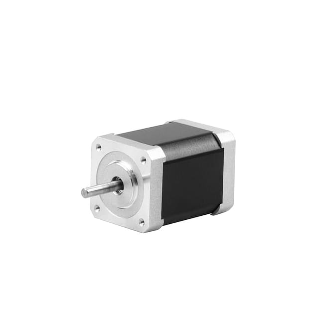
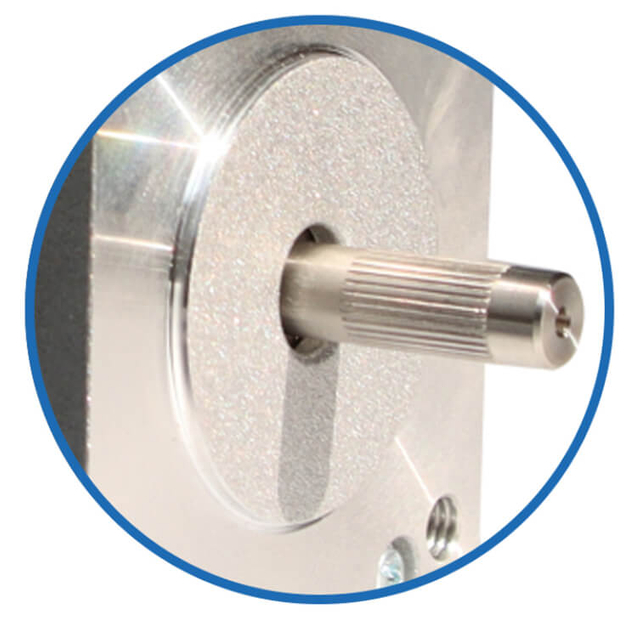
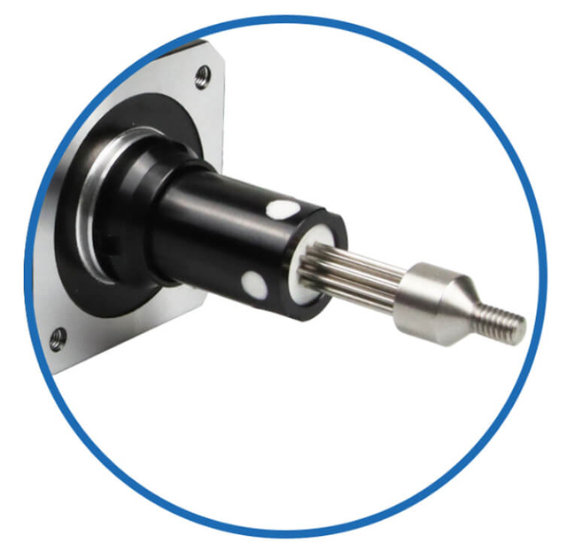
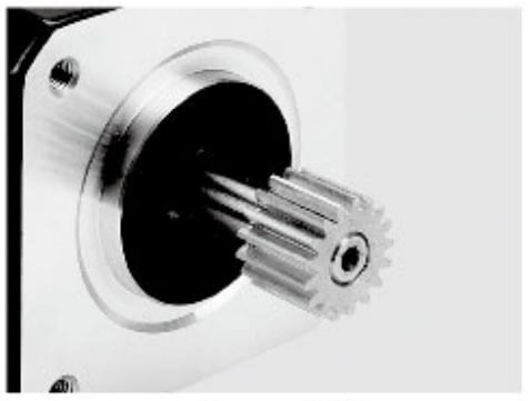
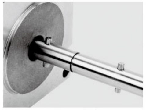
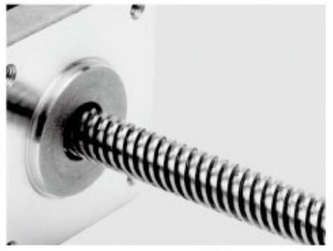
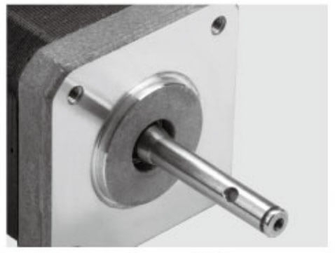
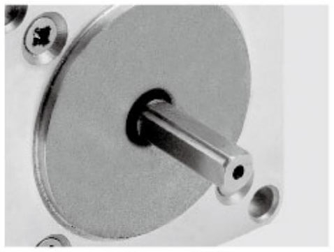
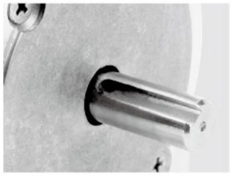
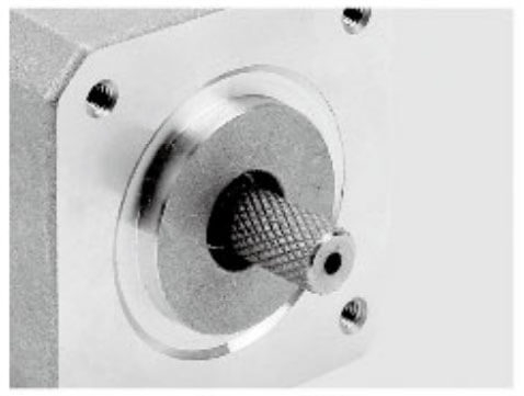
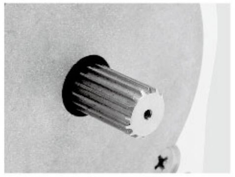
Jkongmotor offer many different shaft options for your motor as well as customizable shaft lengths to make the motor fit your application seamlessly.
Quick Answer: Common Stepper Motor Wire Counts
A stepper motor can have:
2 wires (rare, special designs)
4 wires (most common bipolar stepper motor)
5 wires (unipolar with a common wire)
6 wires (unipolar with two center taps, flexible use)
8 wires (high flexibility: series, parallel, bipolar options)
In most industrial motion control systems, the most common stepper motors are:
Stepper motors come with different numbers of wires because their internal coil windings can be brought out in multiple ways depending on the motor design, the intended driver type, and the performance flexibility required. In simple terms, the wire count reflects how the phases are connected internally and how we can energize the coils to make the motor step.
1) Different Winding Designs (Bipolar vs Unipolar)
The main reason stepper motors have different wire counts is the difference between bipolar and unipolar winding structures.
No center tap in the windings
Current must flow both directions through each coil
Typically has 4 wires (2 coils × 2 wires each)
Why it matters: Bipolar motors are very common today because they work efficiently with modern microstepping drivers and offer strong torque performance.
Windings include a center tap
Current flows in one direction through half of the coil at a time
Typically has 5 or 6 wires
Why it matters: Unipolar motors were popular because early controllers were simpler, but they are less common in modern high-performance motion systems.
2) Center Taps Create More Wires
When a winding has a center tap, it adds extra lead wires coming out of the motor.
6-Wire Stepper Motor
Benefit: Can be wired as unipolar or as bipolar (by ignoring the center taps).
5-Wire Stepper Motor
Tradeoff: Easier unipolar wiring, but not suitable for bipolar driving in most cases.
3) Extra Coils for More Wiring Flexibility (8-Wire Motors)
An 8-wire stepper motor is built for maximum configuration options.
With an 8-wire motor, we can connect coils in:
Series (higher torque at low speed)
Parallel (better torque at higher speed)
Half-coil (lower inductance, faster response)
Why it exists: It allows us to “tune” the motor to match the driver voltage/current and the machine’s speed requirements.
4) Driver Compatibility and Control Method
Manufacturers design different wire counts to match different driver types:
4-wire → modern bipolar chopper drivers
5-wire / 6-wire → unipolar drivers (and some bipolar options for 6-wire)
8-wire → industrial systems needing series/parallel flexibility
The motor wire count ensures the motor can be used with the most suitable control electronics.
5) Performance Needs (Torque, Speed, Efficiency)
Wire configuration changes how the coils behave electrically, affecting:
Inductance
Current draw
Torque curve
High-speed capability
Heat generation
For example:
Series wiring (common with 8-wire motors) increases inductance → better low-speed torque but weaker high-speed torque
Parallel wiring lowers inductance → better high-speed torque but requires more current
So, different wire counts exist because different applications demand different performance priorities.
6) Application-Specific Manufacturing Choices
Stepper motor wire counts also vary because manufacturers optimize for:
Cost reduction (simpler wiring harnesses)
Compact size (small unipolar motors in consumer products)
Industrial customization (8-wire motors for flexible integration)
Legacy system replacement (6-wire motors for older equipment)
Quick Summary
Stepper motors have different numbers of wires because:
Different winding styles (bipolar vs unipolar)
Center taps add wires (5-wire and 6-wire motors)
Multi-coil designs increase flexibility (8-wire motors)
Driver compatibility requirements
Performance tuning needs (torque vs speed tradeoffs)
Different application and cost targets
A 4-wire stepper motor is the most common stepper motor type used in modern machines. It is typically a 2-phase bipolar stepper motor.
What the 4 wires mean
A 4-wire stepper motor has:
2 separate coils
Each coil has 2 wires
Total = 4 wires
You connect one coil to the driver’s Phase A output and the other coil to Phase B.
Key advantages of a 4-wire stepper motor
Compatible with most modern bipolar stepper drivers
Excellent for microstepping
Reliable for CNC, 3D printing, and automation
Simple wiring with fewer mistakes
Best applications
How to identify coil pairs
We typically identify coil pairs using a multimeter:
A 4-wire stepper motor is usually the best option when we want maximum driver compatibility with minimal wiring complexity.
A 6-wire stepper motor is usually a unipolar stepper motor design, but it can also be used as a bipolar motor depending on how we wire it.
What the 6 wires mean
A 6-wire motor contains:
So internally it is basically:
How 6-wire stepper motors are used
We can wire them in two common ways:
Option 1: Unipolar wiring
This works with unipolar stepper drivers, though these are less common today.
Option 2: Bipolar wiring (recommended for modern drivers)
Ignore the two center taps
Use only the two end wires per phase
Total used wires = 4 out of 6
This allows the motor to run on a bipolar driver.
Why 6-wire motors are popular
More wiring flexibility than 4-wire
Good torque characteristics
Often found in older industrial equipment
Where we commonly see 6-wire stepper motors
5-Wire Stepper Motor (Unipolar with Shared Common)
A 5-wire stepper motor is a classic unipolar design often found in small devices.
What the 5 wires mean
In a 5-wire motor:
The center taps are internally connected together
That creates one shared common wire
The remaining 4 wires connect to the coil ends
So we have:
1 common wire
4 phase wires
Total = 5 wires
Important limitation
A 5-wire stepper motor is not ideal for bipolar drivers because the common connection prevents proper independent coil control.
Best use cases
Small positioning mechanisms
Office equipment
Low-cost consumer devices
Compact valve control systems
Typical example
Many small “tin-can” stepper motors come in 5-wire versions because they are cheap and easy to control using basic unipolar driver circuits.
An 8-wire stepper motor is a premium option for industrial applications where we want the ability to optimize for torque, speed, or driver current limits.
What the 8 wires mean
Each phase is split into two separate coils:
Each coil has 2 wire ends:
How we can wire an 8-wire stepper motor
This is where 8-wire motors shine. We can configure them as:
1) Series connection (higher torque at low speed)
2) Parallel connection (better high-speed performance)
3) Bipolar half-coil connection
Best applications for 8-wire stepper motors
Industrial CNC machines
Packaging automation lines
High-speed indexing tables
Semiconductor manufacturing equipment
Heavy-duty positioning systems
When we need maximum flexibility and want to tune performance, an 8-wire motor is often the best long-term choice.
2-Wire Stepper Motor (Rare and Specialized)
A 2-wire stepper motor is uncommon in typical industrial motion control. Most stepper motors require at least two phases, and bringing out only two wires limits control methods.
In practice, 2-wire stepper designs may exist in:
However, in most engineering and sourcing situations, the “2-wire” term is more likely confusion with:
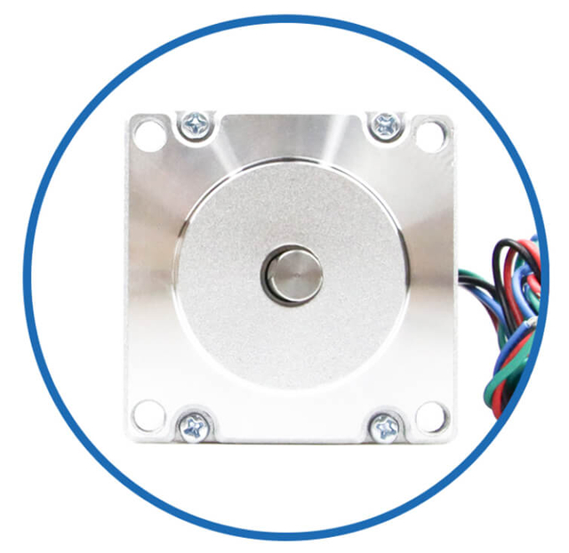
How to Tell How Many Wires Your Stepper Motor Has
To tell how many wires your stepper motor has, we simply need to inspect the motor cable or connector, then confirm the winding layout if necessary. The wire count is important because it determines driver compatibility, wiring method, and how the motor can be controlled.
1) Count the Wires Coming Out of the Motor
The fastest method is to physically count the leads:
4 wires → Most common (bipolar stepper motor)
5 wires → Unipolar with a shared common wire
6 wires → Unipolar with two center taps (can also be wired as bipolar)
8 wires → Industrial stepper with flexible series/parallel wiring options
If the motor uses a plug, count the pins in the connector (or count the wires entering the plug).
2) Check the Label, Datasheet, or Model Number
Many stepper motors have a sticker showing:
Voltage
Current
Step angle
Wiring diagram
Number of leads
If we have the motor part number, the datasheet usually states the lead count clearly (example: “4-lead”, “6-lead”, or “8-lead”).
3) Identify the Wiring Type by Common Wire Counts
Once we know the wire number, we can immediately understand the likely configuration:
4-Wire Stepper Motor
5-Wire Stepper Motor
6-Wire Stepper Motor
8-Wire Stepper Motor
4 separate coils
Can be wired in series, parallel, or half-coil
Best for industrial performance tuning
4) Use a Multimeter to Confirm the Coil Groups (Best Practice)
If wire colors are unclear, we recommend using a multimeter in resistance mode.
For a 4-wire motor
For a 6-wire motor
For a 5-wire motor
For an 8-wire motor
5) Look for Typical Connector Styles (Helpful Clue)
In many applications, stepper motors come with standard connectors:
4-pin connector → usually a 4-wire bipolar motor
6-pin connector → usually a 6-wire motor
8-pin connector → usually an 8-wire motor
However, some manufacturers use larger plugs even for fewer wires, so we still verify by counting actual leads.
Quick Summary
We can tell how many wires a stepper motor has by:
Counting the physical wires
Checking the datasheet or label
Matching the count to common types (4, 5, 6, or 8 wires)
Confirming coil groups with a multimeter
Which Stepper Motor Wire Count Is Best for Your Project?
Choosing the best stepper motor wire count depends on your driver type, speed and torque requirements, and how much wiring flexibility you need. In most real projects, we select between 4-wire, 6-wire, and 8-wire stepper motors because they cover nearly all industrial and automation applications.
Below is a clear, practical selection guide.
Best Choice for Most Projects: 4-Wire Stepper Motor
A 4-wire stepper motor is usually the best option when we want a simple, modern, reliable setup.
Why we choose 4-wire
Works with almost all bipolar microstepping drivers
Easy to wire and troubleshoot
Strong performance for most machines
Commonly available in NEMA 17 / NEMA 23 / NEMA 34
Best for
✅ If we want the safest, easiest choice, 4-wire is the standard recommendation.
A 6-wire stepper motor is ideal when we want extra wiring options or are replacing older equipment.
Why we choose 6-wire
Can run as unipolar (older controllers)
Can run as bipolar by using only the coil ends (like a 4-wire)
Useful for retrofits and compatibility
Best for
Legacy system replacements
Machines using older unipolar drivers
Projects where we may change drivers later
✅ If we want compatibility with both old and new systems, 6-wire is a smart middle option.
Best for High Performance Tuning: 8-Wire Stepper Motor
An 8-wire stepper motor is best when we need to optimize performance based on the machine’s speed and torque profile.
Why we choose 8-wire
It supports multiple wiring modes:
Series (higher torque at low speed, lower current)
Parallel (better torque at higher speed, higher current)
Half-coil (faster response, reduced torque)
Best for
High-end industrial CNC
Packaging and labeling machines
Fast indexing and automation lines
Applications needing both high torque and high RPM
Systems where we want maximum design flexibility
✅ If we need the most configuration freedom, 8-wire is the premium choice.
When 5-Wire Stepper Motors Make Sense (Limited Use)
A 5-wire stepper motor is mainly used in small unipolar applications.
Best for
⚠️ Not recommended for most modern motion systems because it’s typically not compatible with bipolar drivers.
Quick Recommendation Table
4-wire → Best for most modern projects
6-wire → Best for retrofit + flexibility
8-wire → Best for industrial tuning and performance
5-wire → Best for small unipolar-only systems
Final Recommendation
In most projects, we choose:
4-wire stepper motors for the easiest setup and best driver compatibility
6-wire stepper motors when we need mixed compatibility or retrofit options
8-wire stepper motors when performance tuning and flexibility matter most
If you share your driver model, motor size (NEMA 17/23/34), and required speed/torque, we can recommend the best wire count with a matching wiring method.
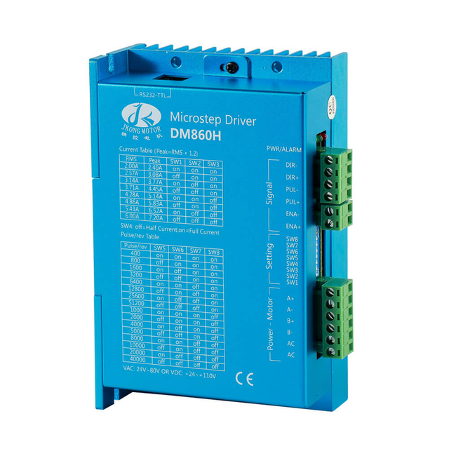
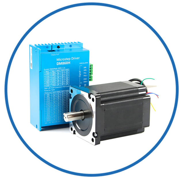
Stepper Motor Wiring Count vs Driver Compatibility
Stepper motor wire count directly determines which driver type we can use and how the motor must be connected. Choosing the correct combination prevents common issues like vibration, overheating, low torque, and missed steps.
Below is a clear compatibility guide for 4-wire, 5-wire, 6-wire, and 8-wire stepper motors.
A 4-wire stepper motor is almost always a 2-phase bipolar motor.
Compatible drivers
✅ Bipolar stepper drivers (most modern drivers)
Not compatible with
❌ Traditional unipolar-only drivers (rare today)
Best use
Why it works well: The driver can reverse current direction through each coil, enabling smooth microstepping and strong performance.
2) 5-Wire Stepper Motor → Unipolar Driver Only
A 5-wire stepper motor is a unipolar motor with a shared internal common wire.
Compatible drivers
✅ Unipolar stepper drivers
Not compatible with
❌ Most bipolar microstepping drivers
(because the common wire prevents proper independent coil control)
Best use
Key point: 5-wire motors are usually not recommended for modern CNC or microstepping applications.
3) 6-Wire Stepper Motor → Unipolar OR Bipolar Driver
A 6-wire stepper motor has two center taps (one per phase), making it very flexible.
Compatible drivers (two options)
✅ Option A: Unipolar driver (use all 6 wires)
✅ Option B: Bipolar driver (use 4 wires only)
Best use
Key advantage: A 6-wire motor can behave like a 4-wire motor when wired correctly.
4) 8-Wire Stepper Motor → Bipolar Driver (Most Flexible)
An 8-wire stepper motor contains four separate coil sections, allowing multiple wiring configurations.
Compatible drivers
✅ Bipolar stepper drivers, using one of these wiring methods:
Series wiring
Parallel wiring
Half-coil wiring
Lower inductance
Higher speed capability
Reduced torque
Best use
Why it’s valuable: We can match the motor to the driver’s voltage/current limits for optimized performance.
Quick Compatibility Table (Simple View)
4-wire motor → ✅ Bipolar driver (recommended)
5-wire motor → ✅ Unipolar driver only
6-wire motor → ✅ Unipolar driver OR ✅ Bipolar driver (using coil ends)
8-wire motor → ✅ Bipolar driver (series/parallel/half-coil options)
Practical Driver Selection Tips
When selecting a driver based on wire count, we typically follow these rules:
For modern motion control, choose 4-wire, 6-wire (bipolar wiring), or 8-wire
Avoid 5-wire motors unless the controller is specifically unipolar
If high speed matters, consider 8-wire parallel wiring (with enough driver current)
Always set driver current limit correctly to prevent overheating and torque loss
Common Mistakes When Wiring a Stepper Motor
Wiring a stepper motor looks simple, but small mistakes can cause vibration, overheating, lost steps, weak torque, or a motor that only “locks” and won’t “locks” and won’t rotate. Below are the most common stepper motor wiring mistakes we see in real projects, and what we do to avoid them.
1) Mixing Up Coil Pairs (Wrong Phase Wiring)
The most common issue is connecting wires that are not from the same coil as a pair.
Symptoms
Motor only shakes or buzzes
Motor locks but does not rotate
Very weak movement or random stepping
Best prevention
2) Reversing One Coil (Motor Runs Rough or Backwards)
If one coil is wired with reversed polarity compared to the other, the motor can behave unpredictably.
Symptoms
Best prevention
3) Assuming Wire Colors Are Standard
Stepper motor wire colors are not universal across brands.
Symptoms
Best prevention
4) Trying to Drive a 5-Wire Motor with a Bipolar Driver
A 5-wire stepper motor usually has a shared common wire internally, making it incompatible with most bipolar microstepping drivers.
Symptoms
Motor does not rotate properly
Driver overheats or trips
Low torque and noisy operation
Best prevention
5) Wiring a 6-Wire Motor Incorrectly (Center Tap Confusion)
A 6-wire motor has two center taps. Many people connect them incorrectly or mix them with coil ends.
Symptoms
Best prevention
For bipolar drivers: use only the two end wires per phase, ignore center taps
Confirm center taps by resistance (center tap shows half resistance to each end)
6) Incorrect 8-Wire Series/Parallel Connection
8-wire motors require correct wiring to form two phases. Wrong series/parallel wiring causes performance issues.
Symptoms
Extremely low torque
Overcurrent faults
Motor runs hot
Poor speed performance
Best prevention
7) Not Matching Driver Current to Motor Rating
Stepper drivers often require you to set the current limit (DIP switches or software).
Symptoms
Too low current: weak torque, missed steps
Too high current: overheating motor/driver, shutdowns
Best prevention
8) Using the Wrong Power Supply Voltage
A stepper system may power on, but perform poorly if voltage is mismatched.
Symptoms
Best prevention
9) Forgetting to Connect Driver Ground Correctly
A missing or incorrect ground connection can cause unstable control signals.
Symptoms
Best prevention
10) Hot-Plugging the Stepper Motor While Powered
Disconnecting or connecting a stepper motor while the driver is powered is a common way to damage drivers instantly.
Symptoms
Best prevention
11) Poor Cable Management and EMI Noise
Stepper motors create electrical noise, especially with PWM microstepping drivers.
Symptoms
Best prevention
Use twisted-pair wiring for each coil
Keep motor cables away from signal wires
Use shielded cable for long runs and ground shielding correctly
12) Loose Connections at Terminals or Connectors
A slightly loose terminal can create intermittent phase loss.
Symptoms
Best prevention
Quick Summary
The most common stepper motor wiring mistakes are:
Wrong coil pairing
Wrong coil polarity
Misusing center taps (6-wire motors)
Incorrect 8-wire series/parallel wiring
Incorrect driver current settings
Hot-plugging motor leads
Poor grounding and noisy cable routing
If you tell us your stepper motor wire count (4/6/8) and driver model, we can provide the correct wiring map and a fast multimeter test method to confirm it.
Final Summary
So, how many wires does a stepper motor have? The most common answers are 4 wires, 6 wires, and 8 wires, with 5-wire stepper motors still appearing in compact unipolar designs. The wire count is not just a physical detail—it directly affects driver selection, wiring method, and performance tuning.
When we choose the correct wire configuration for the right driver, we get smoother motion, stronger torque stability, and fewer integration issues in real-world machines.
FAQs – Stepper Motor & OEM/ODM Customized
What is a stepper motor and how many wires can it have?
A stepper motor is a precision motion device used in automation, available with 2, 4, 5, 6, or 8 wires depending on the winding configuration.
What does the number of stepper motor wires indicate?
The number of wires reflects internal winding structure (bipolar vs unipolar) and affects driver compatibility and torque behavior.
Why are 4-wire stepper motors most common?
4-wire configurations are typical bipolar motors compatible with modern microstepping drivers.
Can a stepper motor with 6 wires be used as a bipolar motor?
Yes — a 6-wire unipolar motor can be wired for bipolar use by ignoring center-tap wires.
What advantages does an 8-wire stepper motor provide?
8-wire motors allow flexible series/parallel connections to tailor torque and speed.
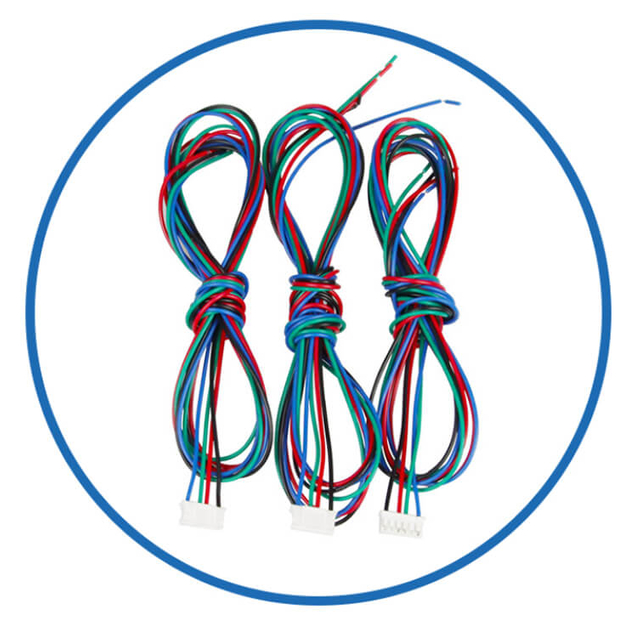
Does JKongmotor offer stepper motors with customized lead wire lengths?
Yes, lead lengths and termination plugs can be customized per application needs.
Can the OEM/ODM factory customize stepper motor connectors?
Yes, custom connectors and wiring harnesses are supported.
What NEMA sizes does JKongmotor support for stepper motor customization?
Customization covers NEMA 8, 11, 14, 16, 17, 23, 24, 34, 42, and 52 sizes.
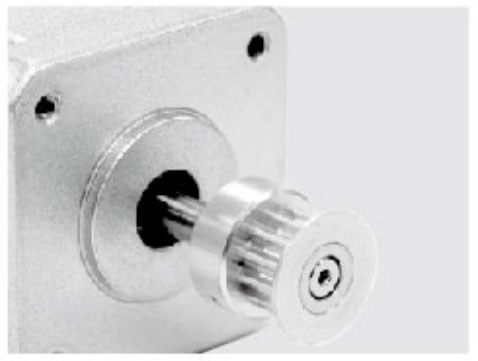
Are custom shaft options available in OEM/ODM stepper motors?
Yes — special shaft sizes, shapes, and features like pulleys/gears can be customized.
Can I get a customized stepper motor with encoder feedback?
Yes, encoders and feedback components can be integrated.
Does the factory integrate gearboxes with stepper motors?
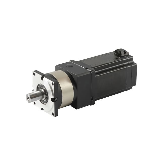
Yes, gearboxes and brake options are available as customized add-ons.
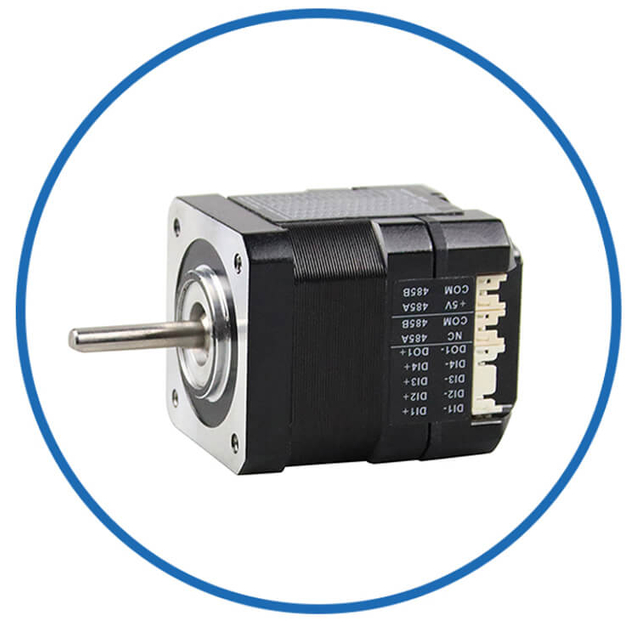
Does JKongmotor provide integrated stepper drives in OEM/ODM solutions?
Yes — integrated drivers with communications like RS485/CANopen/EtherCAT are offered.
Can customized stepper motors be optimized for noise and vibration?
Yes, OEM/ODM customization includes motor optimization for noise reduction and smooth motion.
How does the factory support heavy-duty industry applications?
JKongmotor provides robust customization including IP ratings and mechanical/environmental adaptations.
Is thermal and electrical optimization part of the stepper motor OEM/ODM service?
Yes — electrical matching and thermal performance are assessed for automation systems.
Can OEM/ODM stepper motors be sealed for harsh environments?
Yes — sealed designs and protection options are offered as part of customization.
Does JKongmotor provide technical support for customized motor design?
Yes, professional R&D and design support is available from concept to production.
Can the factory build closed-loop hybrid stepper motors with custom wiring?
Yes, closed-loop hybrid motors with specific hookups and encoders can be created.
Are value-added components like brakes integrated in OEM/ODM motors?
Yes, brakes are available and customizable per project requirements.
How does factory customization improve stepper motor performance?
OEM/ODM customization ensures optimal performance in torque, resolution, environmental tolerance, and wiring compatibility.