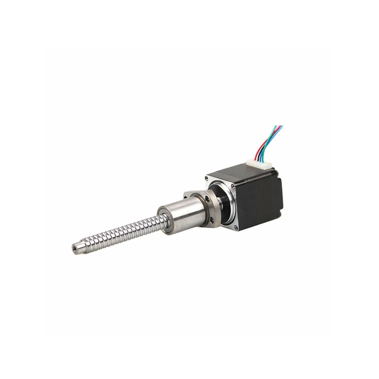
Introduction to Stepper Motors
A stepper motor is a brushless, synchronous electric motor that converts digital electrical pulses into precise mechanical shaft rotation. Unlike conventional motors that spin continuously when power is applied, a stepper motor moves in discrete, fixed angular increments called "steps."
This unique characteristic makes it an ideal choice for applications requiring precise positioning, speed control, and repeatability without the need for a closed-loop feedback system (though encoders can be added for higher reliability in critical applications).
Imagine a motor that "locks" into a specific position when energized and only moves to the next position when the next electrical pulse is sent. Each pulse causes the motor shaft to rotate by a fixed angle (e.g., 1.8° or 0.9°). By controlling the number, frequency, and sequence of pulses, you can precisely control:
Position: Number of pulses determines the angle rotated.
Speed: Frequency of pulses determines the rotational speed.
Direction: Order of pulses determines clockwise or counterclockwise rotation.
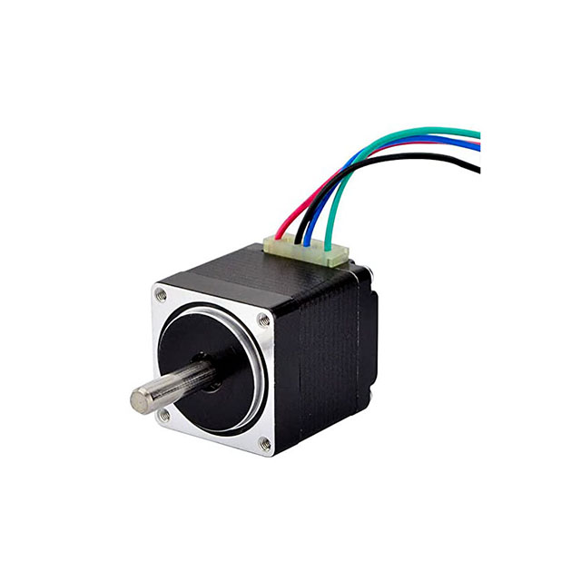
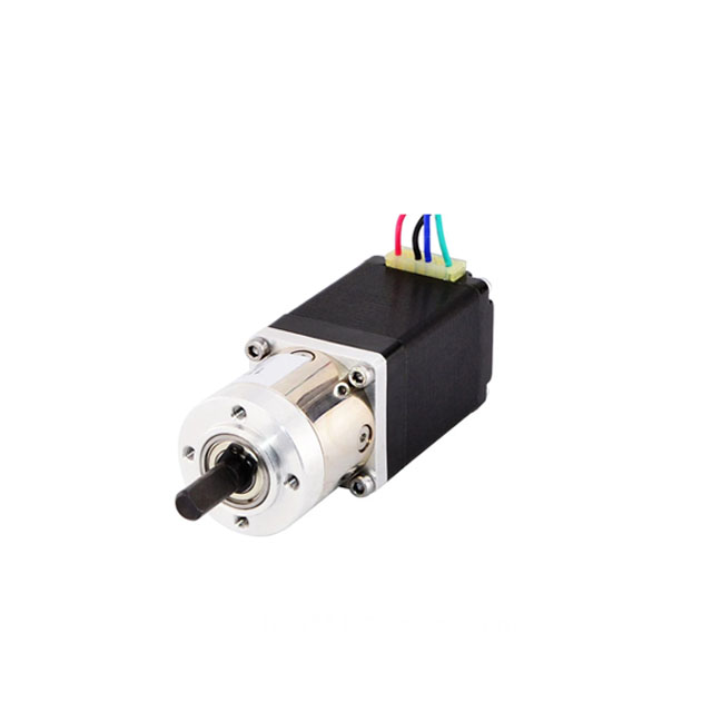
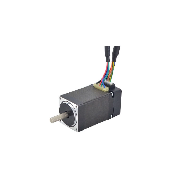
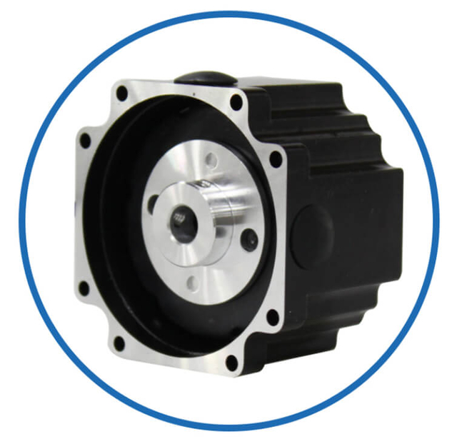
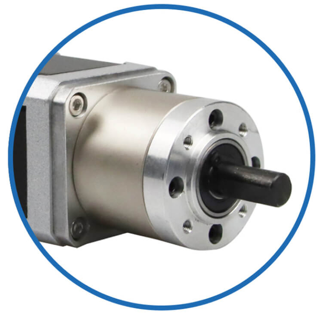
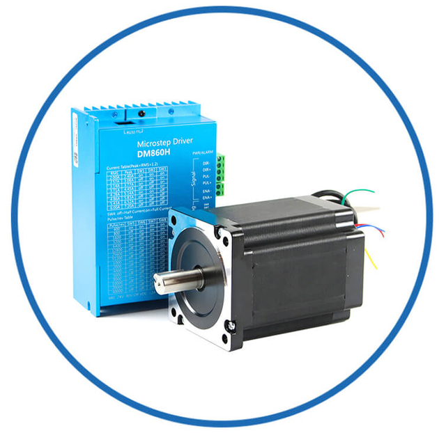
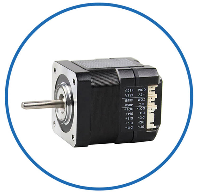
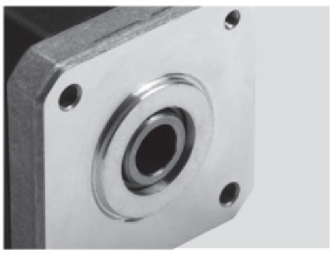
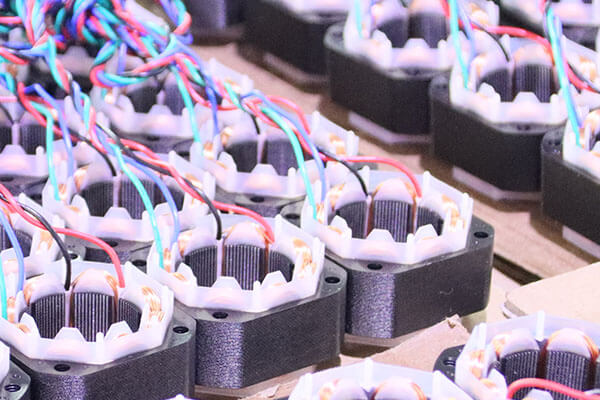
Motor Customized Service
As a professional brushless dc motor manufacturer with 13 years in china, Jkongmotor offer various bldc motors with customized requirements, including 33 42 57 60 80 86 110 130mm, additionally, gearboxes, brakes, encoders, brushless motor drivers and integrated drivers are optional.
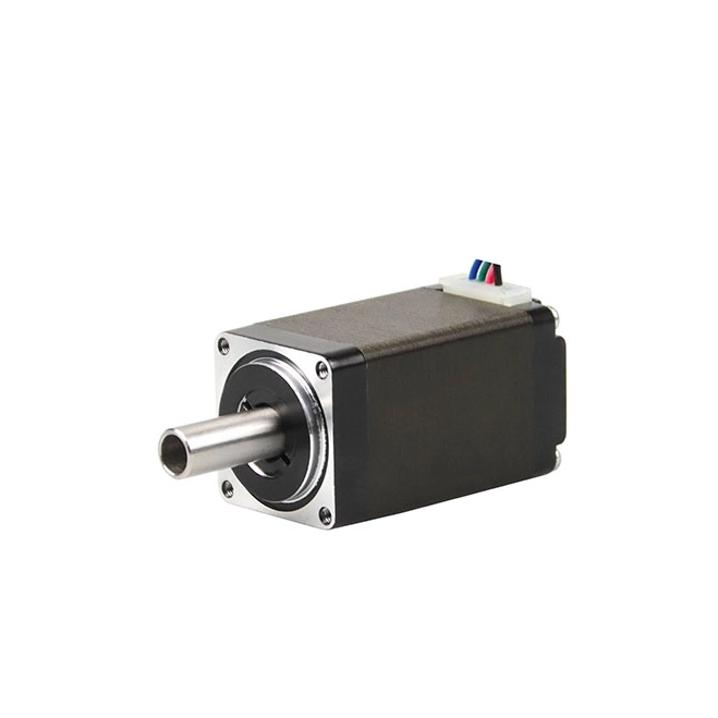
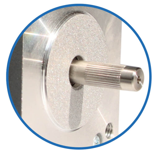
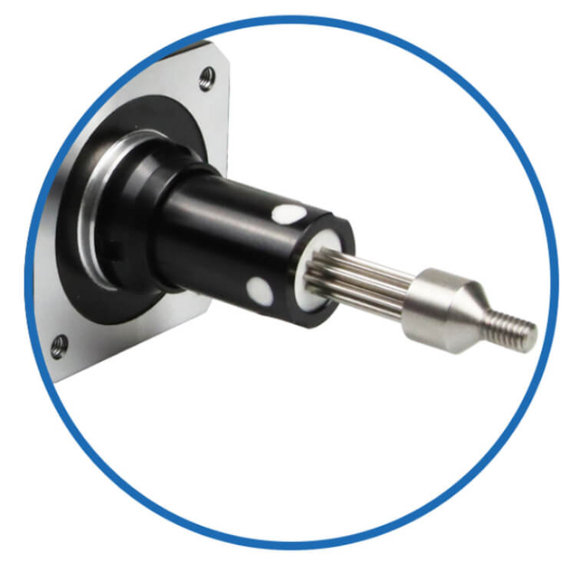
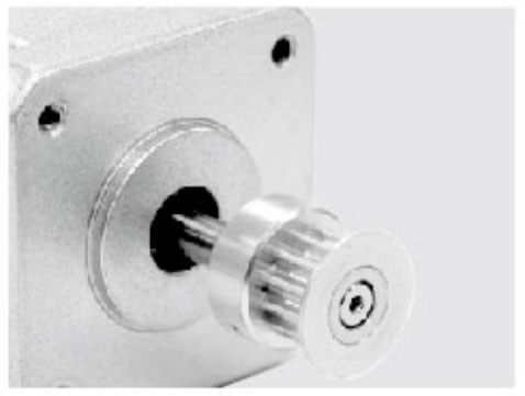
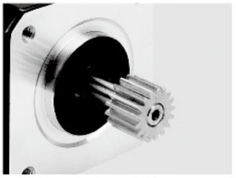
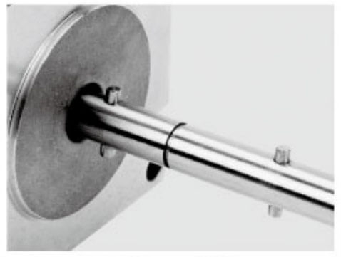
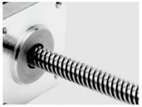
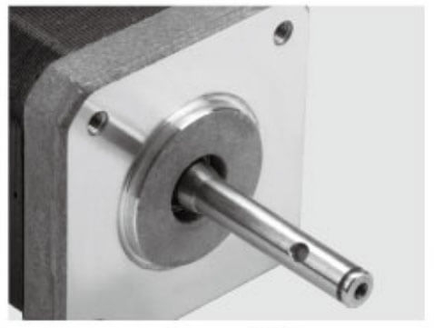
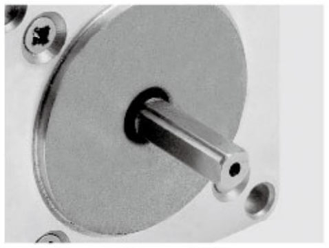
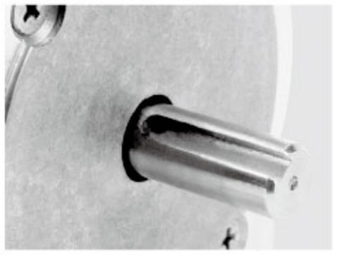
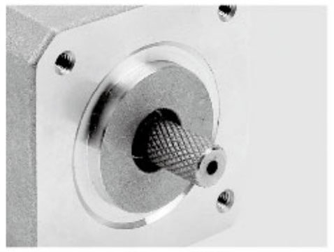
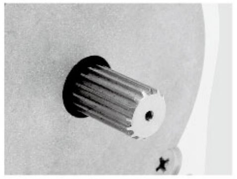
Motor Shaft Customized Service
Jkongmotor offer many different shaft options for your motor as well as customizable shaft lengths to make the motor fit your application seamlessly.
Permanent Magnet (PM):
Rotor: Uses a permanent magnet.
Characteristics: Relatively low step angle (e.g., 7.5° to 90°), provides good detent torque (holds position when off), and has a dynamic response. Often used in low-speed applications.
Variable Reluctance (VR):
Rotor: Made of soft, non-permanent magnet iron with teeth.
Characteristics: No detent torque when unpowered. The rotor moves to the path of minimum magnetic reluctance. Less common today.
Hybrid Synchronous (HS):
Rotor: Combines features of PM and VR types—a permanent magnet with fine teeth.
Characteristics: This is the most common and popular type. It offers very small step angles (typically 0.9° or 1.8°), high torque, excellent holding torque, and good speed performance. Used in most precision applications like CNC machines and 3D printers.
In the realm of precision motion control, stepper motors stand as paragons of digital actuation, offering unparalleled control over position and speed without the need for complex feedback systems. However, a ubiquitous and often misunderstood characteristic of their operation is the generation of heat. We delve into the fundamental principles behind this thermal behavior, moving beyond superficial explanations to provide a comprehensive engineering analysis. Understanding the heating principle of stepper motors is not merely an academic exercise; it is critical for optimizing performance, ensuring long-term reliability, and designing effective cooling solutions for high-duty-cycle applications.
At its core, the heating of a stepper motor is an inevitable consequence of energy conversion inefficiencies. Electrical energy supplied to the motor is converted into mechanical motion, but a significant portion is lost as thermal energy. We identify and examine the three primary sources of these losses.
1. Copper Losses (I⊃2;R Losses): The Dominant Heat Source
Copper losses represent the most substantial contributor to heat generation in a typical stepper motor. These losses occur within the windings of the stator coils, which are made of copper wire. When current flows through these windings, their inherent electrical resistance causes a power dissipation proportional to the square of the current (I) and the resistance (R). This relationship is paramount: P_copper = I⊃2; * R. In a stepper motor driven in a standard manner, the full holding current is maintained in one or more phases even when the motor is stationary, leading to continuous I⊃2;R heating. This is a fundamental distinction from many other motor types and is a key aspect of the stepper motor heating principle. Higher current levels, used to achieve greater torque, exponentially increase these losses. Furthermore, the resistance of copper itself increases with temperature, creating a potential positive feedback loop if heat is not adequately managed.
2. Iron Losses (Core Losses): Hysteresis and Eddy Currents
The stator of a stepper motor is constructed from laminated steel to form the magnetic circuit. Iron losses occur within this core and consist of two components. Hysteresis loss is the energy expended to continually reverse the magnetic domains in the stator iron as the magnetic field alternates direction with each step pulse. The loss is a function of the material's properties, the frequency of stepping, and the magnetic flux density. Eddy current loss results from circulating currents induced within the core material by the changing magnetic fields. These currents flow through the resistance of the steel, generating heat. We mitigate eddy currents by using thin, insulated laminations rather than a solid core. However, at high step rates (high frequencies), iron losses can become a significant contributor to overall motor heating, sometimes rivaling or exceeding copper losses.
3. Mechanical and Friction Losses
Although generally smaller in magnitude compared to electrical losses, mechanical inefficiencies contribute to the thermal budget. Bearing friction is the primary source, dependent on load, speed, and lubrication quality. Additionally, windage losses, caused by the rotor churning the air inside the motor, become more noticeable at very high rotational speeds. While often secondary, these losses compound the thermal load, especially in sealed or high-speed applications.
The Relationship Between Drive Technology and Thermal Output of Customized Stepper Motors
The method by which a stepper motor is driven profoundly impacts its heating characteristics. We must analyze the evolution from basic to advanced drive schemes to fully grasp thermal management.
Linear (Constant Voltage) Drives and Series Resistance
Early and simple drive circuits applied a constant voltage to the motor windings. To limit the current to a safe value, a high-wattage ballast resistor was placed in series with each winding. This approach is thermally disastrous from an efficiency standpoint. The I⊃2;R losses occur not only in the motor windings but also, and often predominantly, in these external resistors, leading to a system-wide inefficient dispersion of heat.
Constant Current Drives (Chopper Drives): The Modern Standard
Modern stepper motor drivers universally employ constant current (chopper) regulation. These drivers use a higher supply voltage and rapidly switch (chop) the voltage to maintain a precise, programmed current level through the winding. This technology offers monumental advantages. It allows for much faster current rise times in the winding inductance, enabling higher step rates and better torque at speed. Crucially, it eliminates the need for external current-limiting resistors, confining the I⊃2;R losses solely to the motor windings themselves. This results in a more efficient system overall, though the motor's intrinsic heating remains.
Current Management Strategies: Standstill and Dynamic Reduction
Sophisticated drivers incorporate features to directly manage thermal output. Static current reduction (also called standstill or idle current reduction) automatically lowers the holding current when the motor has been stationary for a user-defined period. Since holding torque is often only required during motion, this simple strategy can dramatically reduce copper losses during dwell times. More advanced systems may implement dynamic current control based on load, but the core heating principle remains governed by the instantaneous current flowing through the windings.
Heat generated within the motor must travel to the external environment. We examine the thermal path and its implications.
The Thermal Resistance Network
A stepper motor can be modeled as a network of thermal resistances. The hot spot is typically within the stator windings. Heat flows from the windings through the stator laminations to the motor's metal casing (frame). The casing then dissipates heat to the ambient environment via convection and radiation. The interface between the windings and the stator, and the stator to the frame, are critical. High-quality motors use potting compounds or impregnation varnishes to fill air gaps, improving thermal conductivity. The frame surface area, its material (aluminum is superior to steel), and finned designs all directly impact the motor's ability to shed heat.
The Role of the Rated Current Specification
A motor's rated current is not an absolute maximum but is intrinsically linked to its thermal design. It is the current that will cause the windings to reach their maximum allowable temperature (often Class B, 130°C) when the motor is operated under specified conditions, typically at room temperature with the casing freely exposed to still air. Exceeding this current, or operating in a hot ambient environment or with restricted airflow, will cause the insulation to exceed its thermal class, accelerating aging and leading to premature failure.
Consequences of Excessive Heating and Derating Strategies of Customized Stepper Motors
Unchecked temperature rise has direct, deleterious effects on motor performance and lifespan.
Performance Degradation
As winding temperature increases, copper resistance increases. With a constant-current driver maintaining a set current level, the I⊃2;R losses actually increase with temperature, exacerbating the heating. Furthermore, the permanent magnets in the rotor are susceptible to demagnetization at elevated temperatures. If the motor's temperature exceeds the magnet's maximum operating point, a partial or complete loss of magnetic flux occurs, resulting in a permanent and irreversible loss of torque. This is a critical failure mode.
The Imperative of Thermal Derating
To ensure reliable operation, thermal derating is a non-negotiable engineering practice. This involves reducing the operational current (and thus torque) from the rated value to compensate for adverse conditions. We derate for:
High Ambient Temperature: If the environment is hotter, the temperature delta for cooling is reduced.
High Altitude: Thinner air reduces convective cooling.
Restricted Airflow or Enclosed Spaces: This increases the thermal resistance to the environment.
High Duty Cycle or Rapid Sequencing: Operations that minimize cool-down periods require derating.
Derating curves, typically provided in motor datasheets, are essential tools for reliable system design. Ignoring them is a primary cause of field failures related to the heating principle of stepper motors.
Advanced Mitigation Techniques for Demanding Applications of Customized Stepper Motors
When passive cooling and derating are insufficient, active thermal management strategies must be employed.
Forced Air Cooling
The most effective and common method is the use of a blower or fan directed at the motor frame. Even a small amount of airflow can dramatically improve convective heat transfer, sometimes allowing the motor to be operated at or even above its rated current without exceeding temperature limits. The key is ensuring the airflow is directed at the motor's main body.
Heat Sinking and Conductive Cooling
For extreme applications, motors can be mounted onto a heat sink or a thermally conductive mounting plate. Aluminum mounting plates act as a large thermal mass and radiating surface, drawing heat from the motor frame. Special motors with integrated water-cooling jackets represent the pinnacle of thermal management, capable of sustaining very high continuous power outputs by transferring heat directly to a coolant fluid.
Motor Selection and Technology Choices
Ultimately, selecting the correct motor technology is paramount. For applications with extreme duty cycles or in hot environments, we may consider:
Motors with Higher Thermal Class Insulation (e.g., Class F or H).
Large Frame Size Motors: A larger motor running at a lower percentage of its rated current will run cooler than a smaller motor at its maximum current for the same output torque.
Alternative Technologies: For applications requiring continuous high torque with minimal heat, servo motors with their ability to draw current only when needed to counteract load may be a more thermally efficient solution.
The sequence in which the motor's coils are energized affects its torque, smoothness, and step resolution.
Wave Drive (1-phase on):
Only one phase is energized at a time. Simple, low torque, and less stable.
Full Step (2-phase on):
Two phases are energized simultaneously. This is the standard mode, offering higher torque and better stability than wave drive. The motor runs at its full rated step angle.
Half Stepping:
Alternates between one and two phases being on. This doubles the number of steps per revolution (e.g., from 200 to 400 for a 1.8° motor), providing smoother motion and finer resolution, though torque can be less consistent.
Microstepping:
The current is controlled proportionally in the two phases, allowing the rotor to be positioned between full-step positions. This can divide a full step into 256 or more microsteps, resulting in extremely smooth, quiet, and high-resolution motion, though torque is reduced at microstep positions.
Precise Open-Loop Control: Excellent positioning accuracy without expensive feedback systems.
High Holding Torque: Maintains position firmly when stopped, even under load.
Reliable & Durable: Brushless design means less wear and long life.
Excellent Low-Speed Torque: High torque at standstill and low speeds, unlike many DC motors.
Simple Control: Easily interfaced with digital systems like microcontrollers via a driver.
Resonance: Can vibrate or lose torque at certain speeds (often mitigated with microstepping or damping techniques).
Lower Efficiency: Draws substantial current even when stationary holding a position.
Torque Drops with Speed: Torque decreases as rotational speed increases.
Can Lose Steps: If the load torque exceeds the motor's torque, steps can be missed in an open-loop system, leading to positional errors.
Stepper motors are ubiquitous in devices that require precise digital motion control:
3D Printers & CNC Machines: Precise control of the print head/cutting tool.
Robotics: Joint control, gripper movement.
Office & Lab Automation: Printers (paper feed, print head), scanners, automated microscopes.
Medical Devices: Infusion pumps, ventilators, robotic surgery tools.
Consumer Electronics: Camera autofocus and lens zoom mechanisms.
Industrial Automation: Pick-and-place machines, valve control, linear actuators.
Conclusion
In summary, the stepper motor is the workhorse of precision digital motion control. Its ability to move accurately in discrete steps under open-loop control makes it a cost-effective and reliable solution for countless positioning applications across industries. Understanding its types, driving modes, and trade-offs is key to selecting the right motor for any project.
The heating principle of stepper motors is an intrinsic property of their operation, rooted firmly in the physics of electromagnetic energy conversion. The primary driver is copper loss (I⊃2;R loss) within the stator windings, significantly influenced by the chosen drive technology and current level. Secondary contributions from iron losses and mechanical effects compound the thermal load. Successful integration of a stepper motor into a motion control system hinges on a thorough understanding of this thermal dynamic. It requires not only comprehending the sources of heat but also meticulously modeling the thermal pathway, respecting manufacturer derating guidelines, and implementing appropriate cooling solutions. By mastering the principles outlined here, we can design systems that leverage the precision of stepper motors while ensuring robust, reliable, and long-term performance, transforming thermal management from a reactive challenge into a proactive design cornerstone.