Stepper motors are DC-supplied, electronically commutated synchronous motors that require a driver to sequence currents through windings for precise step motion; they can be OEM/ODM customized with tailored size, performance, feedback, and accessories to fit diverse industrial automation needs.
When engineers, buyers, and automation teams ask “Are stepper motors DC motors or AC motors?”, they are usually trying to confirm one thing: what kind of power and drive system is required to run a stepper motor reliably in real applications.
The short answer is simple:
Stepper motors are typically driven by DC power through an electronic stepper driver, even though the motor windings are energized in an alternating sequence that resembles AC operation.
That means stepper motors are not classified the same way as standard AC induction motors or brushed DC motors, because they require a driver-controlled switching pattern to produce motion.
Below, we break down the answer precisely, with practical distinctions that matter in selection, wiring, control, and performance.
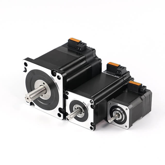
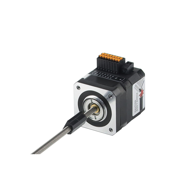
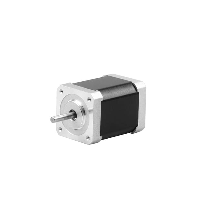
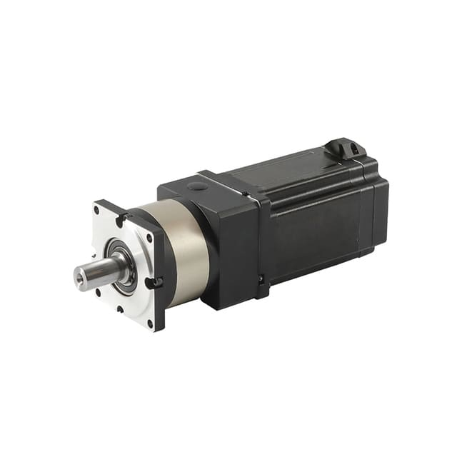
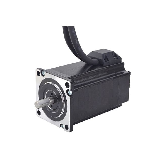
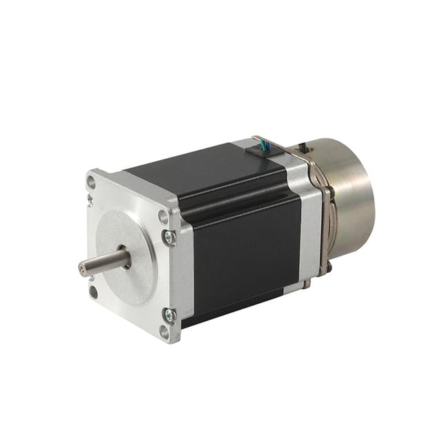
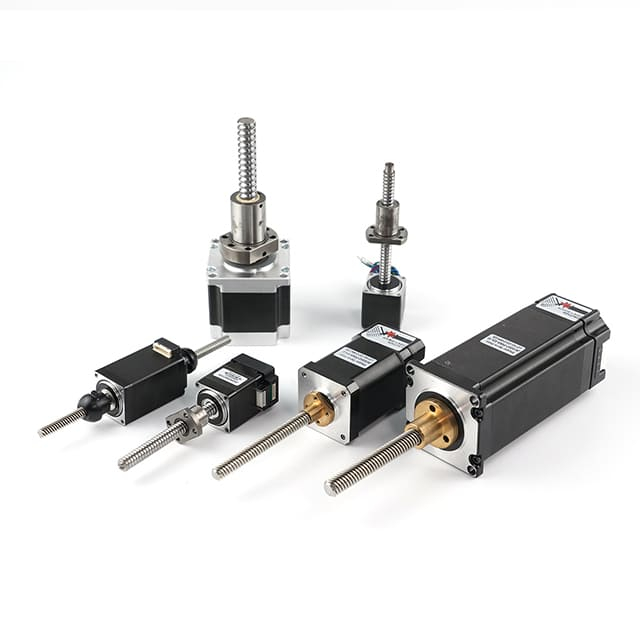
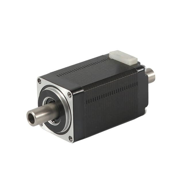
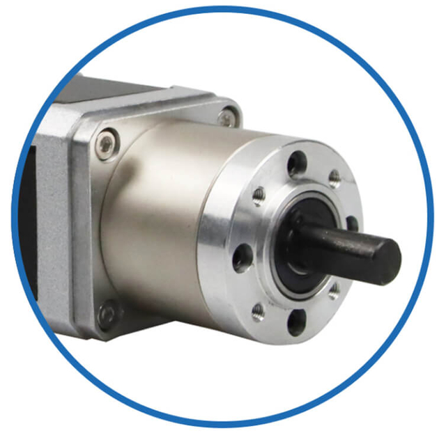
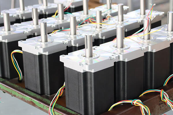
Customized Stepper Motor Types for Heavy Load Industry Applications
Customized Stepper Motor Service & Integration for Heavy Load Industry
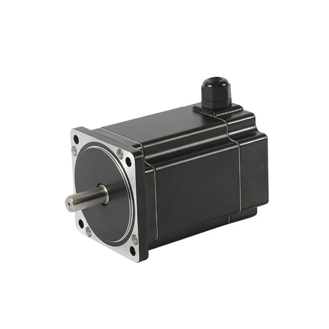
As a professional brushless dc motor manufacturer with 13 years in china, Jkongmotor offer various bldc motors with customized requirements, including 33 42 57 60 80 86 110 130mm, additionally, gearboxes, brakes, encoders, brushless motor drivers and integrated drivers are optional.
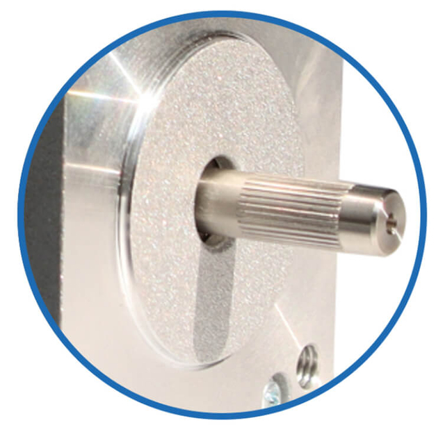
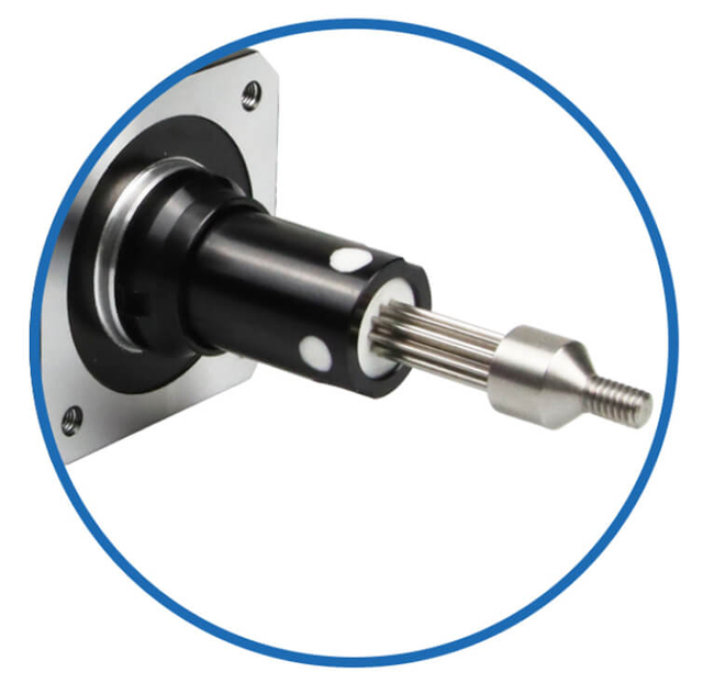
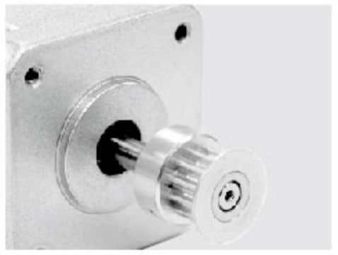
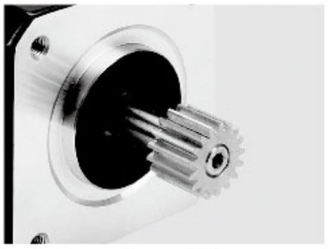
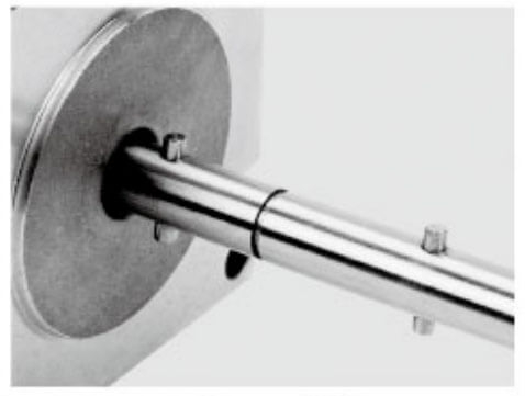
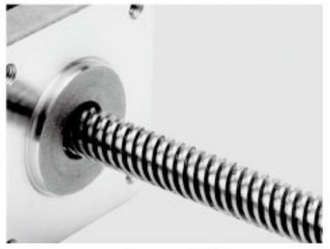
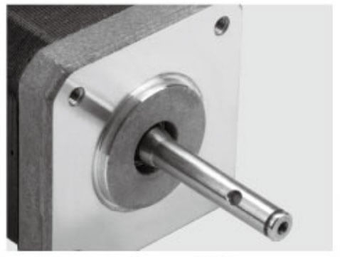
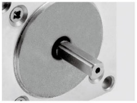
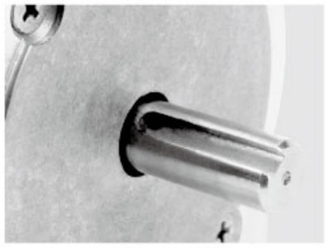
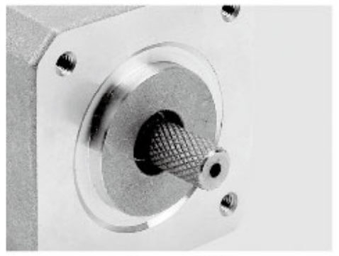
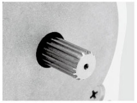
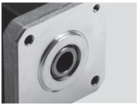
Jkongmotor offer many different shaft options for your motor as well as customizable shaft lengths to make the motor fit your application seamlessly.
Quick Answer: ODM OEM Stepper Motors Are “DC-Driven, Electronically Commutated” Motors
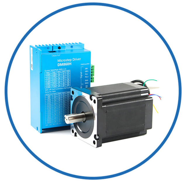
Most stepper systems use:
A DC power supply (commonly 12V, 24V, 36V, 48V, and sometimes higher)
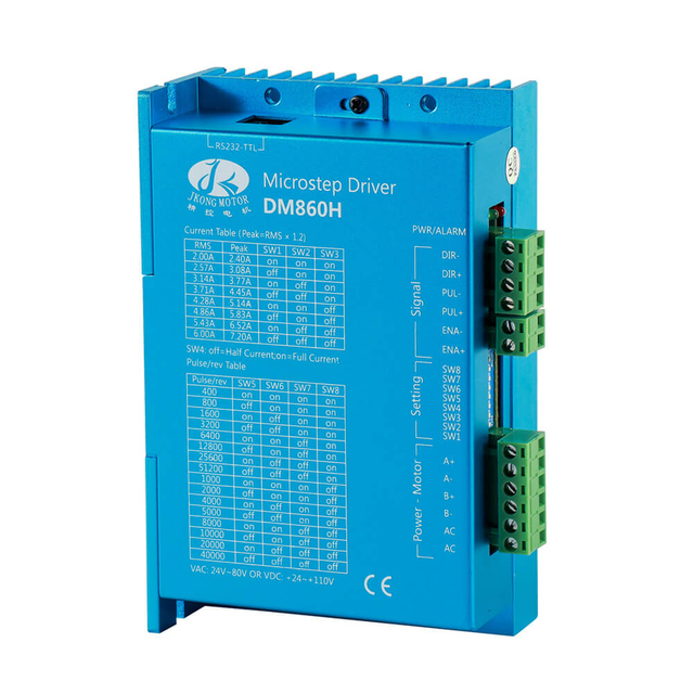
A stepper driver that rapidly switches current through motor phases
A controller sending STEP/DIR pulses (or fieldbus commands)
So, in real-world automation terms, stepper motors are DC-powered motors in the sense that the system runs from a DC bus.
However, the current inside the windings is not simply “DC on and DC off.” The driver creates a sequenced, alternating current direction through the phases to pull the rotor from one stable position to the next.
That is why stepper motors are best described as:
How Stepper Motors Actually Work Electrically (Why the Confusion Happens)
A stepper motor contains multiple stator windings (phases). The driver energizes these windings in a controlled order, generating a rotating magnetic field.
In a typical 2-phase stepper motor, the driver will:
energize Phase A
then Phase B
then reverse Phase A
then reverse Phase B
…and repeat
This produces rotation in discrete increments called steps.
So while the power source is DC, the motor phases experience alternating polarity and varying current levels, especially under microstepping.
This is the main reason people debate whether a stepper is “AC” or “DC.”
The correct practical view is:
Stepper Motors vs DC Motors vs AC Motors (Classification That Matters)
1) Stepper Motors vs Brushed DC Motors
A brushed DC motor typically runs from DC power directly:
Apply DC voltage → motor spins
Reverse polarity → motor reverses
Speed mainly depends on voltage and load
A stepper motor does not behave like that.
A stepper motor requires:
So a stepper motor is not a brushed DC motor, even though it often uses DC power.
Key difference:
Brushed DC motors commutate mechanically using brushes.
Stepper motors commutate electronically using a driver.
BLDC motors are also DC-supplied and electronically commutated. The difference is:
A BLDC system typically uses:
A stepper system typically uses:
So stepper motors are closer to BLDC motors than brushed DC motors, but still serve a different control purpose.
3) Stepper Motors vs AC Induction Motors
AC induction motors run directly from:
They are excellent for:
Stepper motors do not run directly from AC mains. They need:
DC supply
stepper driver
pulse signals
So stepper motors are not AC induction motors in any normal industrial classification.
Do Stepper Motors Run on AC or DC Power Supplies?
Most Stepper Motors Run on DC Power Supplies
In industrial automation, the most common supply types are:
24V DC (very common for PLC cabinets)
48V DC (common for higher torque at speed)
12V DC (common for small devices and hobby CNC)
The stepper driver then regulates the phase current using current chopping (constant-current control).
Important detail: Stepper motors are rated by current per phase, not simply voltage.
That is why you will often see motor specs like:
2.0A/phase
3.0A/phase
4.2A/phase
The driver and supply voltage determine acceleration capability and top speed torque.
Can Stepper Motors Use AC Input Power?
Yes, but only indirectly.
Some stepper drivers accept:
These drivers include an internal power conversion stage that turns AC into DC. The motor itself is still driven using controlled phase excitation.
So even when the driver accepts AC input, the motor is still effectively running from a DC bus internally.
What Type of Motor Is a Stepper Motor, Technically?
Technically, a stepper motor is a synchronous, brushless, electronically commutated motor designed to move in discrete angular steps instead of continuous rotation like standard motors.
1) Stepper Motor = A Synchronous Motor (Most Accurate Classification)
A stepper motor is classified as a synchronous motor because the rotor position stays locked in step with the rotating magnetic field produced by the stator windings—as long as it is not overloaded.
The motor rotates according to the commanded step sequence
It does not “slip” like an induction motor under normal conditions
Position is determined by step pulses, not by supply frequency alone
2) Stepper Motor = Brushless, Electronically Commutated
Stepper motors have no brushes and no mechanical commutator. Instead, a stepper driver energizes the windings in a controlled order.
This makes a stepper motor:
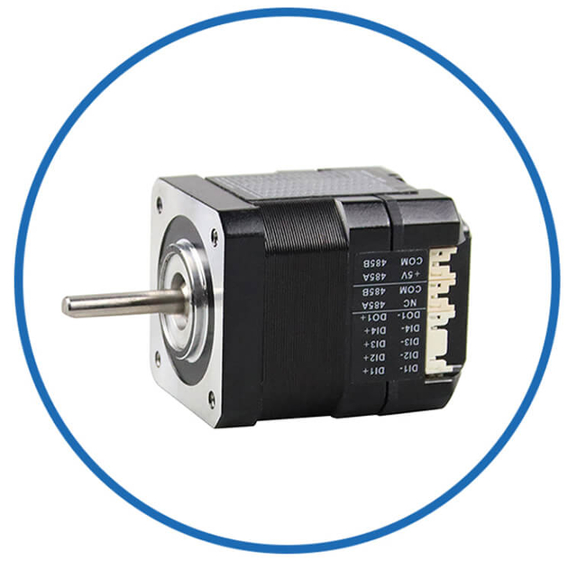
3) Stepper Motor = Multi-Phase (Usually 2-Phase)
Most industrial stepper motors are 2-phase motors, meaning they have two main winding phases (A and B). The driver alternates current through these phases to create rotation.
Some stepper designs can be:
3-phase stepper motors (smoother torque, lower vibration)
5-phase stepper motors (high resolution and smoothness)
4) Stepper Motor = A Positioning Motor (Incremental Motion Actuator)
A stepper motor is technically a positioning motor, because it is built for accurate incremental movement:
Common step angle: 1.8° (200 steps/rev)
High-resolution option: 0.9° (400 steps/rev)
Even finer resolution with microstepping
5) Main Technical Types of Stepper Motors
Stepper motors are further categorized into three core constructions:
Permanent Magnet (PM) Stepper Motor
Variable Reluctance (VR) Stepper Motor
Hybrid Stepper Motor (Most Common in Industry)
Combines PM + toothed rotor structure
Strong torque and accuracy
Widely used in CNC, automation, robotics, and 3D printing
Final Technical Definition
A stepper motor is a brushless synchronous motor that converts digital pulse commands into precise step-by-step mechanical rotation through multi-phase electromagnetic excitation.
Why Customized Stepper Motors Are Usually Considered “DC Motors” in Automation Projects
Stepper motors are usually considered “DC motors” in automation projects because, in practical industrial systems, they are almost always powered from a DC supply and controlled through a DC-driven electronic driver. Even though the motor phases are energized in an alternating sequence, the overall power architecture is DC-based, which is what matters most in machine design, wiring, and purchasing decisions.
1) Stepper Systems Run on DC Power Supplies (Most Common: 24VDC and 48VDC)
In automation cabinets, stepper motors are typically connected to a stepper driver powered by a DC power supply, such as:
24V DC (standard in many PLC control panels)
36V DC (common in mid-range motion systems)
48V DC (popular for higher speed torque and faster acceleration)
Because the supply feeding the driver is DC, many engineers naturally categorize stepper motors as DC motors from a system perspective.
2) Stepper Motors Cannot Run Directly from AC Mains
Unlike traditional AC induction motors, stepper motors cannot be connected directly to:
They require a driver that converts electrical power into controlled phase currents. This is another key reason stepper motors are grouped into the “DC motor” category in real projects.
3) The Stepper Driver Creates the “AC-Like” Phase Switching Internally
Even though the motor is powered from DC, the driver rapidly switches current through the motor windings:
changing the direction of current
controlling current magnitude
sequencing phases to create motion
So while the winding currents may look “AC-like,” they are generated by electronic switching from a DC bus, not by an AC supply line.
4) Control Signals Are Low-Voltage DC Logic (Pulse-Based Motion)
Stepper motors are controlled using digital DC signals, most commonly:
This makes stepper motors feel like DC-controlled devices in automation integration, especially compared to AC motors that rely on frequency-based control.
5) Industrial Automation Standards Favor DC Distribution
Most automation systems are built around DC power distribution because it is:
safer and simpler to manage in control cabinets
compatible with PLCs, sensors, and I/O modules
easy to fuse and protect
standardized at 24VDC across many factories
Since stepper motion hardware fits naturally into this ecosystem, stepper motors are widely treated as DC motion components.
6) Purchasing and Engineering Language Reinforces the “DC Motor” Label
In sourcing and documentation, stepper motors are often grouped with other DC-driven motion products like:
So even though stepper motors are technically synchronous multi-phase machines, the real-world classification becomes:
“Powered by DC, driven by electronics = DC motor category.”
Bottom Line
Stepper motors are usually considered DC motors in automation projects because they are powered by DC supplies, controlled by DC logic signals, and require a DC-fed electronic driver, even though their internal phase excitation is alternating and driver-generated.
Stepper Driver Output: Is It AC or DC?
A stepper driver's output is neither pure AC nor pure DC. In technical terms, it is a switched, controlled, bidirectional current waveform delivered to the motor phases.
In real automation practice, the best description is:
A stepper driver outputs electronically controlled phase currents (often AC-like), generated from a DC power supply.
Why It's Not Pure DC
Pure DC means a constant voltage/current in one direction. Stepper motors require the driver to:
energize Phase A and Phase B
switch current on/off
reverse current direction to reverse magnetic polarity
step through a sequence to rotate the rotor
So the driver output changes direction and magnitude, which is not DC behavior.
Why It's Not Pure AC
Pure AC is a smooth sinusoidal waveform (like mains power). Stepper drivers do not output standard AC frequency power. Instead, they generate:
So it is not traditional AC either.
What the Output Really Looks Like (By Drive Mode)
1) Full-Step / Half-Step Output
In basic stepping modes, the driver output current is closer to a square-wave pattern:
current turns on/off in each phase
polarity switches as the motor advances steps
strong torque, but more vibration and noise
This is best described as switched DC with polarity reversal.
2) Microstepping Output
In microstepping, the driver controls phase currents to approximate sine and cosine waveforms:
This looks more AC-like, but it is still produced by high-frequency switching from a DC bus.
How Drivers Control Current (Chopper Current Regulation)
Most stepper drivers use constant-current chopping, meaning they rapidly switch the output to maintain a target phase current. This allows:
So the driver output is a PWM-style regulated current, not a simple voltage output.
Correct Practical Answer
If you need a clear, project-ready statement:
Input to driver: DC power (e.g., 24VDC / 48VDC)
Output to motor: controlled, alternating phase currents (AC-like waveforms created electronically)
✅ Conclusion: The stepper driver output is a controlled, bidirectional, chopped current waveform—not pure AC or pure DC.
How to Choose the Right Power Supply for a Stepper Motor
Selecting the correct power supply for a stepper motor is critical for reliable motion, torque, and acceleration performance. An undersized or inappropriate supply can cause missed steps, overheating, poor speed, or unstable operation. Here's a detailed guide to choosing the right power supply for your stepper system.
1) Determine the Driver Voltage Range
Stepper drivers are rated for a specific DC input voltage range, typically listed in the datasheet. Common ranges include:
12–24V DC (for small motors and low-speed applications)
24–48V DC (for medium industrial machines)
36–60V DC (for high-speed, high-torque applications)
Rule of thumb: Choose a supply near the upper end of the driver's voltage rating. A higher voltage allows:
But never exceed the driver's maximum voltage, as it can damage both driver and motor.
2) Check Motor Current Rating
Stepper motors are rated by current per phase (e.g., 2A/phase, 3A/phase). The driver uses current regulation to ensure the motor receives exactly this current.
Important: The supply current does not need to equal the sum of phase currents. The driver regulates current using PWM/chopping.
Guideline: Provide a supply that can deliver at least 60–80% of the maximum rated current multiplied by the number of motors if multiple motors share a supply.
3) Calculate Power Supply Current
To size the power supply, consider:
Motor rated current per phase (I_phase)
Number of motors (N_motors)
Driver efficiency (η, typically 80–90%)
4) Factor in Peak vs Continuous Operation
Stepper motors require high current during acceleration. While the driver may limit current, the supply must provide enough voltage and current to maintain performance:
Continuous torque: relates to rated phase current
Peak torque: requires the supply to handle transient spikes
Acceleration and deceleration: require higher instantaneous power
Tip: If your machine performs frequent rapid moves, choose a supply with extra 20–30% current margin.
5) Choose a Supply with Low Ripple and Stable Voltage
Stepper motors respond to the average voltage applied to windings, so power supply quality matters:
Low ripple reduces motor vibration and noise
Stable voltage under load maintains torque and accuracy
Switching-mode power supplies (SMPS) are common in modern automation due to efficiency and compact size
Linear supplies are rare but offer extremely low ripple for sensitive applications
6) Decide on Single vs Multiple Motors Per Supply
If using multiple stepper motors, you can:
Considerations:
Single supply: simpler wiring, but one motor drawing excess current can affect others
Individual supply: more stable for high-precision systems but higher cost
7) Consider Safety and Protection Features
A good power supply should include:
Overcurrent protection to prevent driver or motor damage
Overvoltage protection to avoid insulation failure
Thermal protection to shut down under overheating
Short-circuit protection
These features increase reliability in industrial environments.
8) Verify Physical and Environmental Compatibility
When installing the supply:
Ensure enclosure fits the cabinet
Confirm operating temperature range matches your application
Verify ventilation or cooling if the supply operates near full load
Environmental factors can affect voltage stability and lifetime.
9) Match Supply Voltage With Stepper Driver Type
Stepper drivers come in:
Always match the supply voltage and current to the driver specifications, not just motor ratings. The driver regulates current internally, so the driver dictates supply requirements, not the motor alone.
10) Example Selection Process
Suppose you have:
2-stepper motors, each 3A/phase, 1.8° step angle
Stepper driver rated for 24–48V DC input
Microstepping mode for smooth motion
Steps:
Select supply voltage: 48V DC (upper range for faster stepping)
Calculate supply current: 3A × 2 motors × 1.2 ≈ 7.2A
Choose 48V DC, 8A power supply to provide margin
Ensure supply has overcurrent, overvoltage, and thermal protection
Confirm the supply fits in the control cabinet and matches ambient conditions
Conclusion
Choosing the right power supply for a stepper motor is a balance of:
Voltage near the driver's maximum for high-speed performance
Sufficient current to handle peak loads and multiple motors
Low ripple and stable operation for smooth motion
Safety features to protect the system
By carefully analyzing the motor ratings, driver requirements, and system load, you ensure reliable, precise, and long-lasting stepper motor operation in your automation project.
Does a Stepper Motor Need a Controller Like a Servo?
A stepper motor does not necessarily require a closed-loop controller like a servo motor for most applications. Stepper motors are typically designed to operate open-loop, meaning they move a specific number of steps based on the input pulses without feedback. However, there are important considerations when deciding whether to use a controller or feedback system.
1) Open-Loop Operation Is Standard for Stepper Motors
In most industrial and hobbyist setups:
The stepper motor receives STEP/DIR pulses from a controller or PLC
The motor moves a fixed step angle per pulse (e.g., 1.8° per step)
The system assumes the motor reaches the commanded position
Advantages of open-loop operation:
Simpler wiring and setup
Lower cost (no encoder or feedback required)
Adequate for many CNC machines, 3D printers, and robotic axes
Limitations:
If the load exceeds the motor torque, the motor can skip steps without detection
Loss of synchronization can result in position errors
High acceleration or abrupt loads increase the risk of missed steps
2) When Closed-Loop Control Is Beneficial
Stepper motors can be combined with encoders or closed-loop drivers to form a hybrid system:
The driver monitors rotor position via the encoder
It adjusts current or pulses if the motor misses steps
The system prevents step loss and improves torque performance
Applications that benefit from closed-loop stepper control:
Key point: Even with closed-loop feedback, the motor itself remains a stepper motor. The controller merely improves reliability, similar to a servo system.
3) Differences Between Stepper and Servo Controllers
| Feature | Stepper Motor Controller | Servo Motor Controller |
| Feedback | Optional | Required |
| Torque | Fixed (based on current) | Variable (feedback-controlled) |
| Accuracy | Step-based, open-loop | Closed-loop, continuously adjusted |
| Complexity | Simple | More complex and expensive |
| Cost | Lower | Higher |
Conclusion: Stepper motors can operate without a controller like a servo, but adding closed-loop control enhances reliability and allows higher performance.
4) Practical Recommendation
For light-duty, predictable loads, use a standard open-loop stepper setup
For high-speed, high-accuracy, or high-inertia applications, consider closed-loop stepper drivers
Always ensure the stepper driver is compatible with your motor and properly sized for voltage and current
Bottom Line: A stepper motor does not inherently need a servo-style controller, but modern automation systems can benefit from feedback-enhanced control to prevent step loss, improve torque, and increase system reliability.
Common Applications Where Customized Stepper Motors Are Used (And Why Power Type Matters)
Stepper motors are widely used in automation, robotics, and precision motion systems because of their accurate positioning, repeatable steps, and reliable performance. Understanding the type of power they use—DC via an electronic driver—is essential for proper system design and integration.
1) CNC Machines
Usage:
Stepper motors are used to drive the X, Y, and Z axes in CNC routers, milling machines, and engraving machines.
Why power type matters:
CNC controllers typically output pulse signals to stepper drivers powered by 24V or 48V DC.
Using a DC-driven system allows precise step-by-step control of the cutting or engraving tool.
Proper voltage ensures the motor can maintain torque at higher speeds, preventing skipped steps and lost cuts.
2) 3D Printers
Usage:
Stepper motors control extruder feed, bed movement, and print head positioning.
Why power type matters:
Printers use 24V DC supplies, which are easy to integrate with microcontroller boards.
Stepper drivers convert DC power into sequenced phase currents, allowing microstepping for smooth, precise printing.
Accurate DC power ensures repeatable layer deposition and reduces print defects.
3) Pick-and-Place Machines
Usage:
High-speed pick-and-place systems in electronics assembly rely on stepper motors to move robotic arms and positioning tables.
Why power type matters:
DC-powered stepper systems provide predictable torque and speed control.
The ability to control phase currents from a DC bus ensures rapid acceleration without losing steps.
Power stability is critical for precise placement of components.
4) Labeling, Packaging, and Conveyor Systems
Usage:
Stepper motors are used in label applicators, filling machines, and conveyor indexing systems.
Why power type matters:
Most packaging machines are powered from 24V DC control cabinets.
Stepper motors provide repeatable indexing at each step of the process.
DC power allows easy integration with PLCs and sensor systems for synchronized operation.
5) Medical and Laboratory Equipment
Usage:
Stepper motors drive syringe pumps, dosing machines, and laboratory robotic arms.
Why power type matters:
DC supply ensures precise, controlled movement, which is critical for accurate dosing or sample handling.
Stepper drivers can regulate phase current to maintain consistent torque in delicate applications.
Low-voltage DC is safer in sensitive medical environments compared to high-voltage AC.
6) Camera Sliders and Pan-Tilt Systems
Usage:
Stepper motors are used for cinematic camera motion, automated surveillance, and precision photography.
Why power type matters:
DC power allows quiet, smooth operation with microstepping.
Stable DC supply prevents jerky motion that could blur images or disrupt timing.
Low-voltage DC systems are compatible with portable and battery-operated setups.
7) Textile and Embroidery Machines
Usage:
Stepper motors control needle movement, thread positioning, and pattern selection.
Why power type matters:
DC power provides consistent step motion, critical for maintaining pattern accuracy.
Electronic drivers allow microstepping, reducing vibration and improving stitch quality.
Power supply stability ensures machines can run for long production cycles without losing synchronization.
8) Valve Actuation and Dosing Systems
Usage:
Stepper motors rotate valves or dosing mechanisms in chemical, food, or industrial fluid systems.
Why power type matters:
DC-driven stepper systems provide repeatable angular movement, ensuring precise fluid control.
Controlled phase currents allow torque to overcome varying load conditions without overshoot.
Using DC power simplifies integration with existing automation panels.
Why the Power Type Matters Across Applications
Predictable Torque: DC supply with current-regulated drivers ensures the stepper motor produces reliable torque throughout its motion.
Precise Positioning: Controlled DC-driven phase currents allow exact step increments, crucial for high-precision applications.
Integration with Control Systems: Most automation controllers, PLCs, and microcontrollers operate on DC logic, making DC-powered stepper systems easier to implement.
Safety and Efficiency: DC power reduces risks compared to high-voltage AC, allows compact switching power supplies, and supports energy-efficient PWM drivers.
Bottom Line
Stepper motors dominate applications where precision, repeatability, and reliability are key. Across CNC machines, 3D printers, pick-and-place systems, medical devices, and automated packaging, the DC-powered, electronically driven nature of stepper motors ensures smooth operation, accurate positioning, and easy integration with modern automation systems. Proper voltage and current selection are critical to achieving optimal performance in all these applications.
Key Takeaways: Are Stepper Motors DC or AC?
To answer the question clearly and correctly:
Stepper motors are generally powered by DC through a stepper driver
They are not AC induction motors
They are not brushed DC motors
They use electronically switched phase currents that alternate direction
Their drive waveform can resemble AC, especially under microstepping
So the most accurate statement is:
Stepper motors are DC-supplied motors with electronically controlled phase excitation, often producing AC-like waveforms inside the windings.
FAQs – Stepper Motor & OEM/ODM Customized
Are stepper motors DC motors or AC motors?
Stepper motors use a DC supply and a driver to energize phases in sequence, so they are best described as DC-supplied and electronically commutated, not traditional AC induction motors.
Do stepper motors run directly from AC mains?
No — stepper motors don’t run directly from AC mains; they require a driver that converts AC input into a DC bus and sequences current through windings.
What type of power supply do stepper motors typically use?
Most stepper systems run on DC power supplies such as 12V, 24V, 36V, or 48V depending on torque and speed requirements.
How do stepper motor windings work electrically?
The driver alternates current through multiple phases (e.g., A/B coils), creating stepwise rotational motion even though the input is DC.
Are stepper motors synchronous or asynchronous?
Stepper motors are synchronous, meaning the rotor steps in lock-step with the controlled magnetic field produced by the stator windings.
Can stepper motors be OEM/ODM customized?
Yes — manufacturers provide OEM/ODM customization for shafts, dimensions, gearboxes, encoders, IP ratings, and integration options.
What industries use customized stepper motors?
Customized steppers are used in automation, robotics, packaging, textile machinery, medical devices, and heavy-load industrial applications.
Can I get a closed-loop stepper motor in an OEM order?
Yes — OEM/ODM services can provide closed-loop steppers with feedback systems for enhanced accuracy.
What’s the difference between stepper motors and brushed DC motors?
Brushed DC motors spin continuously with simple DC input; stepper motors move in discrete steps with controlled phase switching.
Can a stepper motor be supplied with AC input power?
Only indirectly: drivers can accept AC input and convert it to DC internally to run the stepper system.
Are stepper motors closer to BLDC motors or brushed DC motors?
Stepper motors are closer to BLDC (brushless DC) in being electronically commutated, but they serve different control purposes focused on step positioning.
Can OEM customization include motor drivers?
Yes — custom motor packages often include tailored drivers and integrated control electronics.
Is motor torque affected by AC or DC supply?
Stepper torque is governed by current and coil excitation, not AC mains frequency; DC bus and driver performance define torque.
What sizes can customized stepper motors be made in?
OEM/ODM customization covers multiple frame sizes and flange standards to fit different machine profiles.
Are stepper motors suitable for precision positioning?
Yes — steppers are designed for accurate incremental motion with defined step angles.
Do customized stepper motors come with environmental ratings?
Yes — OEM/ODM options can include IP protection levels to meet operating environment demands.
Can stepper motor OEM orders include accessory components?
Yes — accessories like brakes, encoders, couplings, and gearboxes can be part of customization.
Do stepper motor specs focus on current or voltage?
Stepper motors are usually rated by current per phase; drivers manage voltage and current for performance.
Can OEM customization support integrated motion systems?
Yes — manufacturers can deliver integrated motor + driver + feedback systems as part of custom solutions.
Are customized stepper motors compliant with industrial standards?
High-quality customized steppers typically meet certifications like CE, RoHS, and ISO quality standards.