Selecting a custom stepper motor for a robotic system requires engineering alignment of torque, motion, electrical and mechanical integration, and JKongmotor’s OEM/ODM customized service delivers tailored robotic motors with integrated drives, encoders, frame sizing, shafts, protection, and co-engineering support to achieve reliable, precise robotic performance and scalable production.
Choosing the right custom stepper motor for a robotic system is not just about picking a motor that “fits.” In real robotics projects, the motor must match torque demand, motion profile, control method, mechanical integration, and environmental constraints—while staying efficient, stable, and manufacturable at scale.
In this guide, we outline a practical, engineering-first approach to selecting a custom stepper motor for robotic systems, focusing on performance, reliability, and OEM-level customization decisions that reduce risk and improve production consistency.
Define the Robotic Motion Requirement Before Motor Selection
Before choosing any stepper motor, we must define how the robotic axis moves. A robotic system may require high-speed indexing, precise positioning, continuous rotation, or multi-axis synchronized motion. Each use case drives different motor specifications.
Key motion parameters we must confirm:
Target load mass and inertia
Required acceleration and deceleration
Operating speed range (RPM)
Duty cycle (continuous, intermittent, peak bursts)
Positioning accuracy and repeatability
Holding behavior (hold position under load vs freewheel)
If we skip this step, we risk oversizing (wasted cost and heat) or undersizing (missed steps and instability).
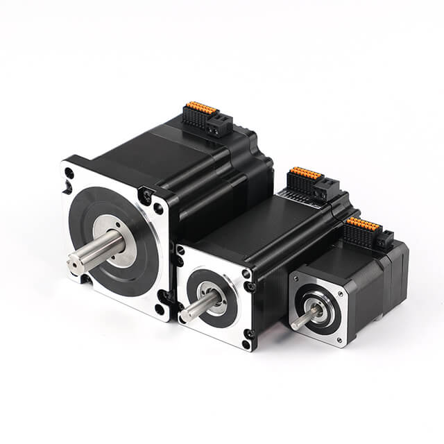
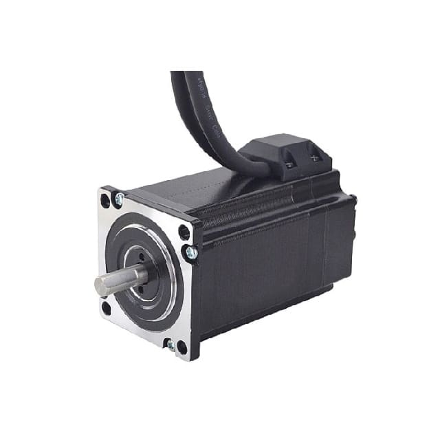
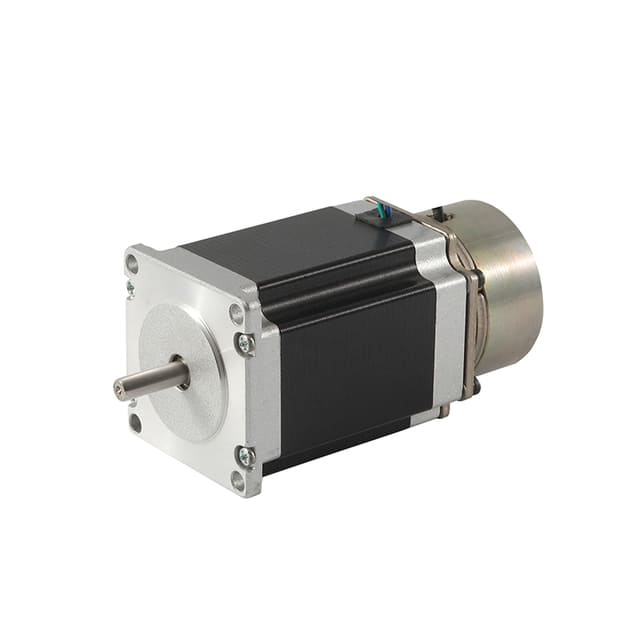
Customized Stepper Motor Types for Heavy Load Industry Applications
Customized Stepper Motor Service & Integration for Heavy Load Industry
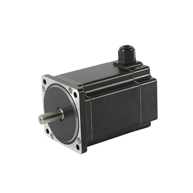
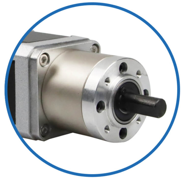
As a professional brushless dc motor manufacturer with 13 years in china, Jkongmotor offer various bldc motors with customized requirements, including 33 42 57 60 80 86 110 130mm, additionally, gearboxes, brakes, encoders, brushless motor drivers and integrated drivers are optional.
Jkongmotor offer many different shaft options for your motor as well as customizable shaft lengths to make the motor fit your application seamlessly.
Selecting the correct stepper motor type is one of the most important decisions in robotic motion design. The motor type directly affects torque output, positioning accuracy, speed stability, smoothness, noise, and how easily the motor can be integrated into a robotic joint, axis, or actuator module. Below, we break down the main stepper motor types used in robotics and how to choose the best one for your system.
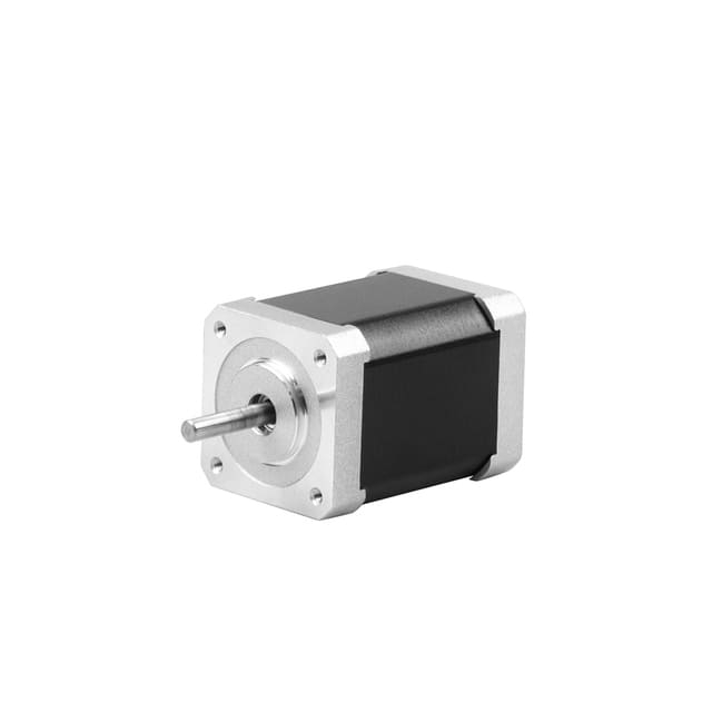
1) Permanent Magnet (PM) Stepper Motor — Best for Cost-Sensitive Compact Robotics
A Permanent Magnet (PM) stepper motor uses a permanent magnet rotor and a simple stator structure. It is typically lower cost and easier to drive, but it delivers less torque and precision than hybrid designs.
Best robotic applications for PM stepper motors:
Small robotic grippers with light loads
Basic automation modules with short travel distances
Compact positioning stages where torque demand is limited
Low-speed indexing mechanisms in simple robots
Key advantages in robotic systems:
Limitations to consider:
Lower torque density compared to hybrid stepper motors
Less ideal for high-precision robotic axes
Not the best choice for high acceleration or dynamic payload changes
If the robot needs stable torque under varying loads, PM stepper motors usually won’t be the best long-term solution.
2) Variable Reluctance (VR) Stepper Motor — Best for Specialized High-Speed Light Loads
A Variable Reluctance (VR) stepper motor operates using a soft iron rotor with no permanent magnets. The rotor aligns with the energized stator poles, producing step-by-step motion.
Best robotic applications for VR stepper motors:
High-speed lightweight motion platforms
Specialized robotic positioning systems
Certain lab automation tools where speed matters more than torque
Key advantages in robotic systems:
Limitations to consider:
Lower torque than hybrid steppers
Less common in modern robotic designs
More sensitive to load changes in practical robotics
For most mainstream robotic systems, VR steppers are less popular because robotics usually demands stronger torque stability.
3) Hybrid Stepper Motor — The Best All-Around Choice for Robotics
A Hybrid stepper motor combines the best features of PM and VR designs. It uses a magnetized rotor with toothed structure, producing strong torque and high positioning resolution. This is the most widely used stepper motor type in robotics because it delivers a strong balance of precision, torque, control stability, and scalability.
Best robotic applications for hybrid stepper motors:
Robotic arms and joints
Linear actuators and lead screw drives
Gantry robots and XY tables
Pick-and-place robotics
Automated inspection and camera motion systems
3D printing and precision motion modules
Key advantages in robotic systems:
High holding torque for maintaining robotic position
Strong running torque for motion under load
Excellent compatibility with microstepping drivers
Better repeatability for robotic positioning tasks
Wide availability of customization options
Limitations to consider:
For most projects, a custom hybrid stepper motor is the best foundation when building a reliable robotic motion axis.
4) Closed-Loop Stepper Motor (Encoder Stepper) — Best for Robotics That Cannot Lose Steps
A closed-loop stepper motor combines a stepper motor (usually hybrid) with an encoder feedback system. This design allows the controller to detect position error and correct it in real time, making it ideal for robotic systems where load conditions can change unexpectedly.
Best robotic applications for closed-loop stepper motors:
Robot joints with varying payloads
High-speed robotic motion requiring accuracy
Vertical axes (Z-axis lifting) where slipping is risky
Robotic systems requiring fault detection
Industrial robotics with higher reliability requirements
Key advantages in robotic systems:
Prevents missed steps
Improves stability under dynamic loads
Reduces vibration and heat compared to overdriving open-loop motors
Supports higher performance without moving to full servo cost
Limitations to consider:
If the robotic system must be production-grade and fault-tolerant, a custom closed-loop stepper motor is often the best upgrade.
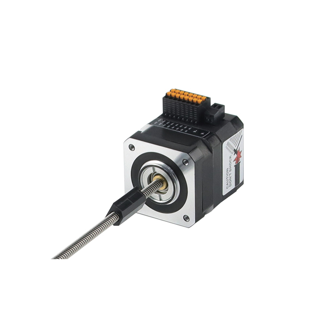
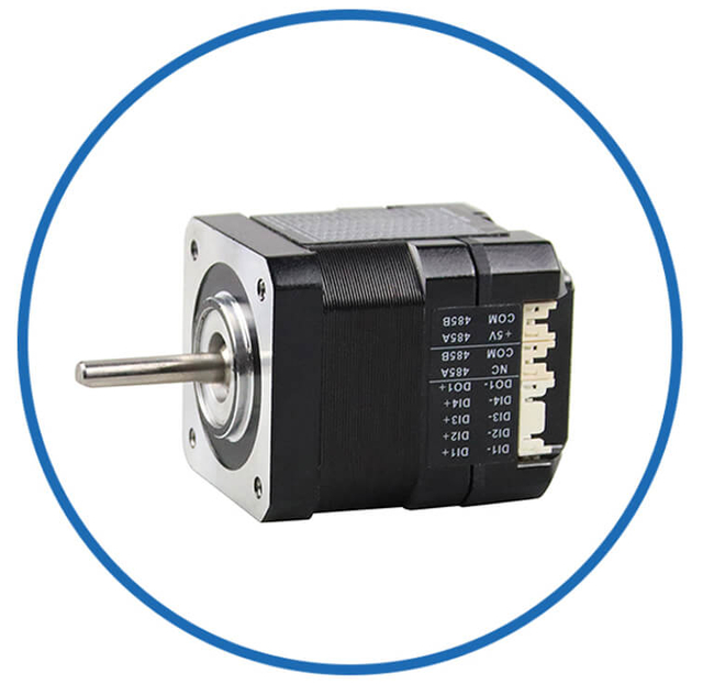
An integrated stepper motor combines the motor body with a built-in driver (and sometimes encoder). This reduces wiring complexity and improves installation speed, especially in robots where space is tight and assembly time matters.
Best robotic applications for integrated stepper motors:
Mobile robots and AGVs
Compact robotic actuators
Modular robotics platforms
Robotic inspection devices
Key advantages in robotic systems:
Clean design with fewer external components
Simplified wiring and fewer failure points
Faster assembly and easier maintenance
Limitations to consider:
For OEM robotics, integrated solutions often improve production consistency and reduce field failures.
Quick Selection Guide: Which Stepper Motor Type Should We Choose?
Choosing the best stepper motor type for a robotic system depends on your load, speed, accuracy, reliability, and budget targets. Use this quick guide to make the right decision fast—without overcomplicating the selection.
1) Choose a Permanent Magnet (PM) Stepper Motor if:
PM steppers are best when the robotic motion is simple and light-duty.
✅ Best fit for:
Light loads and low torque demand
Low-speed motion (basic indexing)
Cost-sensitive robotic projects
Compact devices with limited performance requirements
Typical robotic uses:
2) Choose a Variable Reluctance (VR) Stepper Motor if:
VR steppers are mainly for specialized robotics where speed matters more than torque.
✅ Best fit for:
High-speed stepping with very light loads
Specialized positioning systems
Projects where torque is not the priority
Typical robotic uses:
Hybrid steppers are the most common and reliable choice for robotics.
✅ Best fit for:
High precision positioning
Medium to high torque requirements
Stable holding performance
Robotics needing repeatable motion and strong axis control
Typical robotic uses:
If you are unsure, choose a hybrid stepper motor first.
4) Choose a Closed-Loop Stepper Motor if:
Closed-loop steppers are ideal when the robot cannot risk losing position.
✅ Best fit for:
Variable payloads
High acceleration and fast cycles
Vertical lifting axes (Z-axis)
Robotics needing error detection and correction
Production robots requiring higher reliability
Typical robotic uses:
Integrated steppers simplify design, wiring, and installation.
✅ Best fit for:
Robots needing compact structure
Projects requiring fast assembly
Systems with limited wiring space
OEM robotics needing clean modular design
Typical robotic uses:
Fast Decision Summary (One-Line Rule)
Lowest cost + light load → PM stepper
High-speed + very light load → VR stepper
Most robotics applications → Hybrid stepper
No missed steps allowed → Closed-loop stepper
Compact wiring + easy integration → Integrated stepper
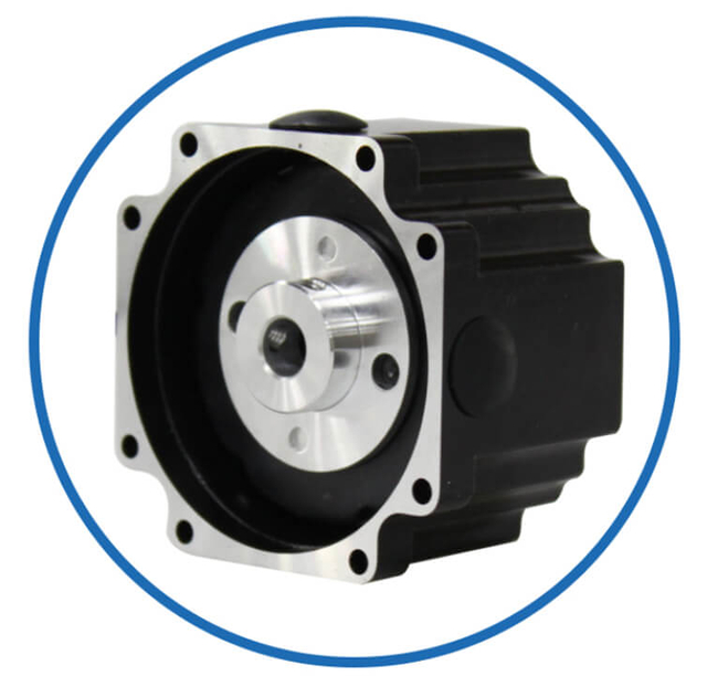
Select the Correct Frame Size and Mounting Standard
Choosing the right stepper motor frame size and mounting standard is critical for robotic systems because it directly impacts available torque, mechanical fit, assembly speed, structural rigidity, and long-term motion stability. A motor that is electrically perfect but mechanically incompatible will create redesign delays, vibration issues, and alignment failures.
Below is the practical way we select the correct frame size and mounting details for a custom stepper motor for robotic systems.
1) Start with the Robot’s Space Envelope and Mechanical Layout
Before selecting a frame size, we must confirm the physical boundaries of the robotic module:
Maximum motor diameter allowed by the robot housing
Available motor length (stack length clearance)
Mounting face clearance for screws and tools
Cable exit direction and routing space
Neighbor component interference (gearbox, encoder, bearings, covers)
In robotics, the motor is often installed inside a compact joint or actuator module, so space constraints typically drive frame size first, then torque is optimized within that envelope.
2) Understand What Frame Size Really Means (NEMA and Metric Standards)
Most robotic stepper motors are selected using NEMA frame sizing, which defines the mounting face dimension, not the performance.
Common stepper motor frame sizes used in robotics:
NEMA 8 (20mm) – ultra-compact robotic modules
NEMA 11 (28mm) – small grippers and light actuators
NEMA 14 (35mm) – compact axes and short-stroke robotics
NEMA 17 (42mm) – most common for precision robotic motion
NEMA 23 (57mm) – higher torque joints and linear drives
NEMA 24 (60mm) – space-efficient high torque alternative
NEMA 34 (86mm) – heavy-duty industrial robotics
Key point: A larger frame generally allows higher torque and better heat handling, but increases weight and inertia—both of which can reduce robotic responsiveness.
3) Match Frame Size to Torque and Inertia Requirements
Frame size affects robotic performance beyond torque. It also affects rotor inertia, which impacts acceleration and deceleration.
We choose a smaller frame when:
The robot needs fast response
The axis must accelerate quickly
Weight must be minimized (robot arms, mobile robots)
The load is light but precision matters
We choose a larger frame when:
The robot must deliver high torque
The axis must hold position under load (holding torque priority)
The system uses gear reduction and needs strong input torque
The robot runs high duty cycle and must manage heat
In robotic joints, selecting the correct balance of torque vs inertia is often more important than simply choosing the strongest motor.
4) Choose the Correct Motor Body Length (Short, Medium, Long Stack)
Within the same frame size, stepper motors come in different stack lengths. Longer motors usually provide more torque because they have more active magnetic material.
Typical selection logic:
Short body → compact robotics, low inertia, lower torque
Medium body → balanced torque and size for most robotic axes
Long body → maximum torque, higher inertia, more heat capacity
For custom robotic systems, we often optimize stack length to hit a specific torque target without changing the mounting footprint.
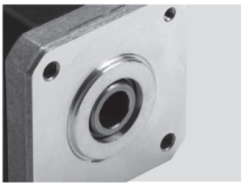
5) Confirm the Mounting Face Details (Flange, Pilot, Bolt Pattern)
Mounting standard selection is where many robotics assembly issues occur. A stepper motor must align perfectly with the robot’s structure to prevent:
We must confirm these mounting details:
Mounting Face (Flange Size)
The flange must match the robot bracket design. Even small mismatches can force redesign.
Pilot Diameter (Center Register)
The pilot ensures accurate centering of the motor on the bracket. This improves:
concentricity
shaft alignment
repeatable assembly
Bolt Hole Pattern
Confirm:
bolt hole spacing
screw size (M2.5 / M3 / M4 / M5 typical)
thread depth requirements
through-hole vs tapped-hole preference
For production robotics, we recommend using a pilot-based alignment rather than relying only on bolts for centering.
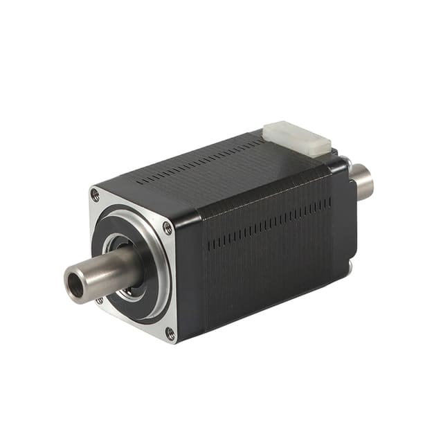
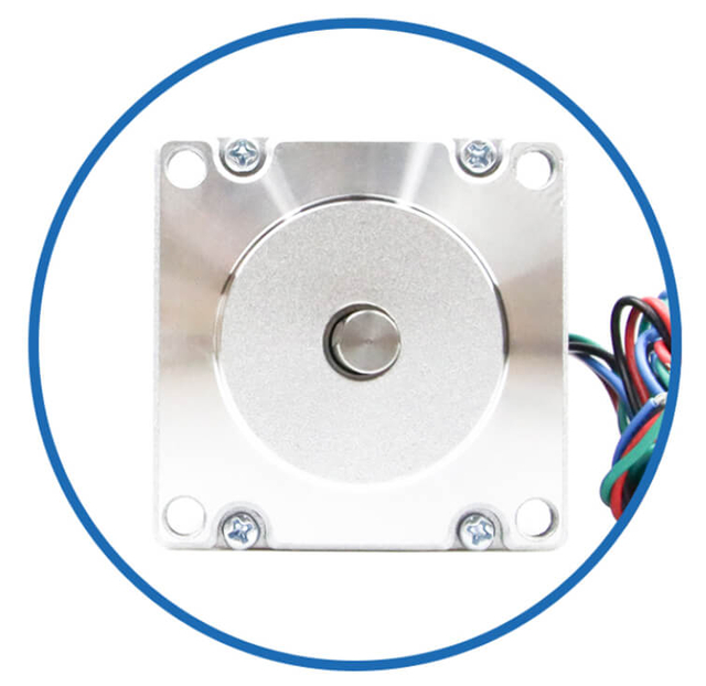
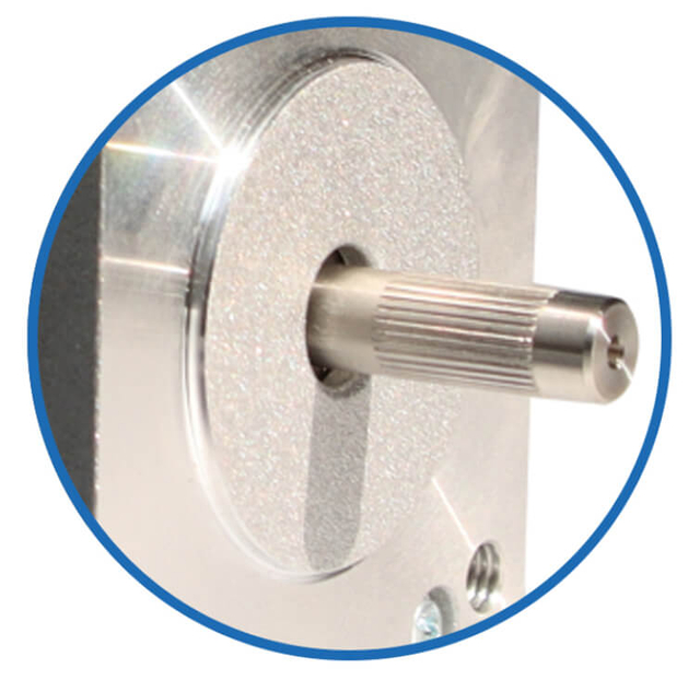
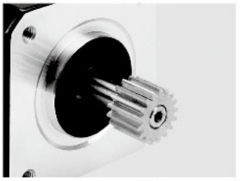
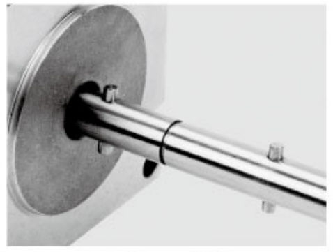
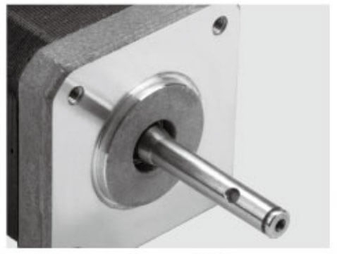
6) Select Shaft Size and Output Geometry for the Robotic Axis
Shaft selection must match the coupling method and torque transmission needs.
Common shaft options for robotic stepper motors:
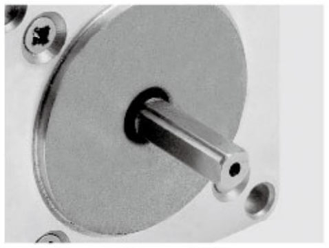
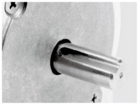
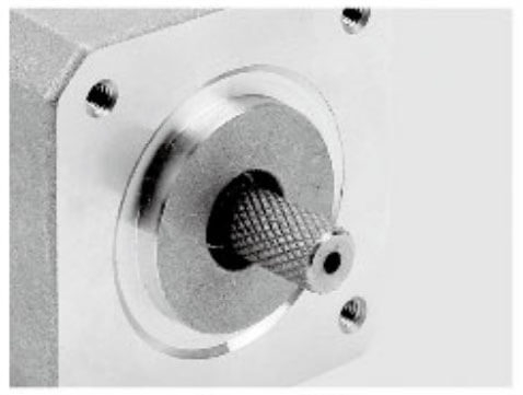
Round shaft (simple coupling)
D-cut shaft (anti-slip for set-screw couplings)
Keyway shaft (high torque transmission)
Double shaft (encoder + mechanical output)
Hollow shaft (compact, pass-through wiring or direct integration)
Key shaft parameters we must specify:
For robotics, a D-cut or keyed shaft is often preferred when the system experiences frequent acceleration, reversing, or shock loads.
7) Choose the Right Mounting Orientation and Cable Exit Direction
Robotic modules are compact and usually assembled in tight spaces. We must select cable exit direction that supports clean routing and reduces bending stress.
Options include:
A custom motor can be designed with:
This improves reliability in robots that move continuously, such as multi-axis arms or AGVs.
8) Consider Gearbox and Actuator Integration Standards
If the robotic system uses a gearbox or linear actuator, we must ensure the motor mounting matches the reducer interface.
Common robotics integration scenarios:
Stepper motor + planetary gearbox
Stepper motor + worm gearbox
Stepper motor + harmonic drive adapter
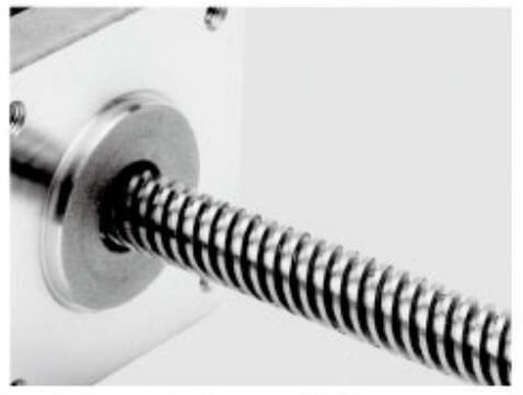
Stepper motor + lead screw / ball screw actuator
In / ball screw actuator**
In these cases, the correct mounting standard includes:
gearbox input flange pattern
shaft coupling type (clamp, spline, keyed)
axial preload compatibility
allowable radial load on motor bearings
For high-precision robotics, gearbox alignment and shaft concentricity are essential to prevent backlash and wear.
9) Validate Assembly Tolerances for Repeatable Production
For custom robotic systems moving into mass production, we must ensure the motor mounting is not “prototype-only.”
We recommend confirming:
A consistent mounting standard ensures every robot performs the same without manual adjustments.
Quick Frame Size Recommendations for Robotics
Here is a practical reference for robotic projects:
NEMA 8 / 11 → micro-robotics, compact grippers, light motion
NEMA 14 → compact actuators, small inspection robotics
NEMA 17 → most robotic axes, best balance of size and torque
NEMA 23 → stronger joints, medium payload robot arms, linear drives
NEMA 34 → heavy-duty industrial robotics and high torque actuators
Best Practice: Lock the Mounting Standard Early
In robotic system development, we should finalize the frame size + mounting face + shaft spec early, because these decisions affect:
A properly selected custom stepper motor frame size and mounting standard reduces redesign risk and improves robotic reliability from prototype to production.
Choose Step Angle and Microstepping Strategy for Precision
Stepper motors are known for step-based positioning. For robotics, we must match step resolution to system requirements.
Common step angles:
1.8° (200 steps/rev) – the most common hybrid stepper option
0.9° (400 steps/rev) – higher resolution, smoother motion
For robotic systems requiring smoothness and quiet operation, 0.9° step angle combined with microstepping is often preferred.
Microstepping benefits:
However, microstepping also increases control complexity and may reduce effective torque per microstep. We must select the driver and current settings carefully.
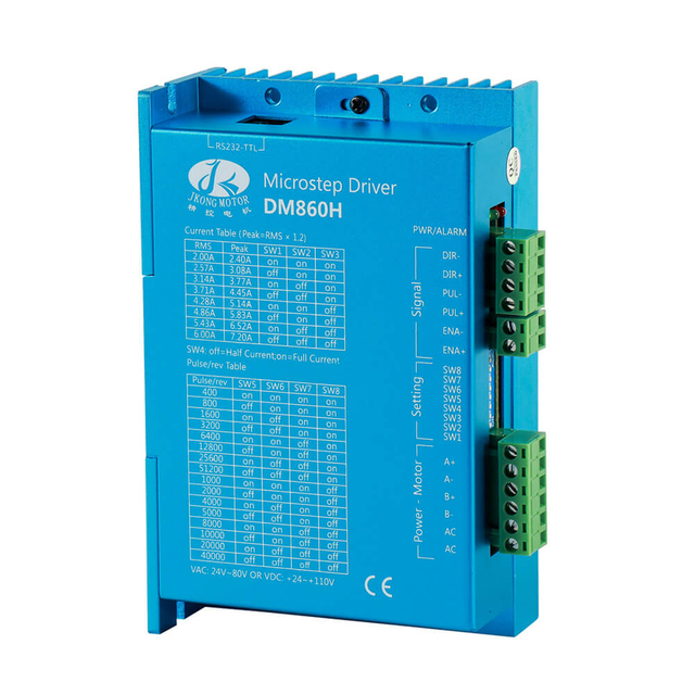
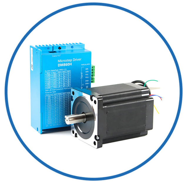
Match the Stepper Motor to the Driver: Current, Voltage, and Inductance
Stepper motor performance depends heavily on the driver and power system.
Key electrical parameters:
For robotic systems, we typically prefer bipolar stepper motors because they provide stronger torque and better driver compatibility.
Why Inductance Matters in Robotics
Lower inductance generally improves high-speed performance because current rises faster in the windings. This is critical for robotics where speed and acceleration are important.
When customizing, we can optimize:
The goal is to achieve stable torque at operating RPM without overheating.
When designing a robotic system, one of the most critical decisions is whether to use an open-loop or closed-loop stepper motor. This choice directly impacts accuracy, reliability, responsiveness, and system cost. Selecting the wrong control approach can lead to missed steps, poor motion smoothness, or unnecessary over-engineering. Below, we break down the differences and provide guidelines for robotic applications.
1) Open-Loop Stepper Motors: Simplicity and Cost-Effectiveness
An open-loop stepper motor operates without position feedback. The controller sends pulses, and the motor assumes it moves exactly as commanded. This system is simple, inexpensive, and widely used in robotic applications where load conditions are predictable.
Best applications for open-loop stepper motors in robotics:
Small robotic arms with lightweight payloads
Low-speed, repetitive motion tasks
Robotic grippers or conveyors where load torque is consistent
Short-stroke linear actuators
Advantages of open-loop control:
Lower cost due to no encoder or feedback electronics
Simple wiring and driver setup
Easier integration for compact robotic modules
Reliable for predictable, low-torque applications
Limitations in robotics:
Missed steps can occur if the load exceeds torque capability
Performance drops under sudden acceleration or external disturbances
No automatic error correction
Open-loop stepper motors are ideal for cost-sensitive or low-precision robotic systems, but caution is required if loads vary or the robot operates at high speeds.
2) Closed-Loop Stepper Motors: Accuracy and Reliability Under Load
A closed-loop stepper motor includes an encoder or position sensor that provides real-time feedback to the controller. The system monitors the motor’s actual position and adjusts current to prevent missed steps and maintain accurate motion, even under variable load conditions.
Best applications for closed-loop stepper motors in robotics:
Robot arms with variable payloads
Multi-axis pick-and-place robots requiring high precision
Vertical lifting axes where load fluctuations are significant
High-speed or acceleration-intensive robotic joints
Systems needing fault detection or automatic error correction
Advantages of closed-loop control:
Prevents lost steps under sudden load changes
Optimizes torque usage, reducing heating and power consumption
Enables smoother motion and reduced vibration
Supports higher acceleration and complex motion profiles
Limitations:
Higher cost due to encoders and more complex drivers
Slightly more complex wiring and control setup
System tuning may be required for optimal performance
Closed-loop stepper motors are the preferred choice for precision robotics, production robots, and collaborative applications where reliability and accuracy are critical.
3) Key Factors to Consider in the Decision
When choosing between open-loop and closed-loop for a robotic system, evaluate:
| Factor | Open-Loop Stepper | Closed-Loop Stepper |
| Cost | Low | Higher |
| Accuracy under variable load | Limited | Excellent |
| Complexity | Simple | Moderate |
| Vibration / Smoothness | Moderate | Reduced |
| Fault Detection | None | Real-time monitoring |
| Acceleration / Speed | Limited by torque drop | Optimized with feedback |
| Maintenance / Reliability | Lower upfront | Higher long-term reliability |
4) Practical Guidelines for Robotics
Use Open-Loop when:
The robot carries light, consistent loads
Motion is slow and predictable
Budget constraints are strict
Ease of integration is prioritized
Use Closed-Loop when:
Loads vary or sudden acceleration is required
Positioning accuracy and repeatability are critical
The robot performs multi-axis synchronized motion
Production reliability and fault tolerance are required
5) Hybrid Approach: Optional Closed-Loop Integration
In some robotics applications, it is possible to upgrade an open-loop motor with encoder feedback, creating a hybrid solution. This provides:
Stepper simplicity with added error correction
Real-time monitoring without moving to a full servo motor
Improved torque utilization and reduced heating
Hybrid closed-loop stepper solutions are increasingly popular in collaborative robots, AGVs, and industrial pick-and-place systems.
6) Summary Recommendation
For cost-sensitive or low-precision robots, open-loop stepper motors are sufficient.
For high-precision, high-speed, or variable-load robotics, closed-loop stepper motors are strongly recommended.
Consider custom closed-loop stepper motors for robotic systems where torque, position, and reliability must be optimized across multiple axes.
Selecting the correct loop configuration ensures that the robot operates smoothly, maintains accuracy under load, and reduces the risk of system failure.
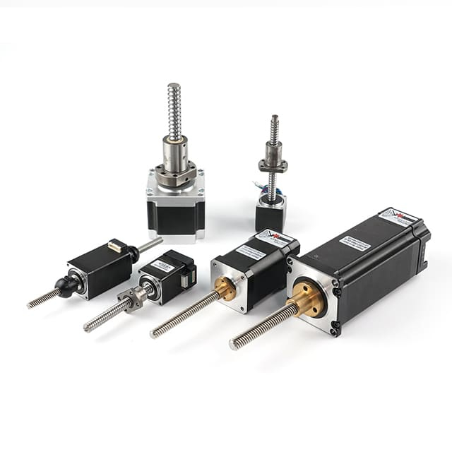
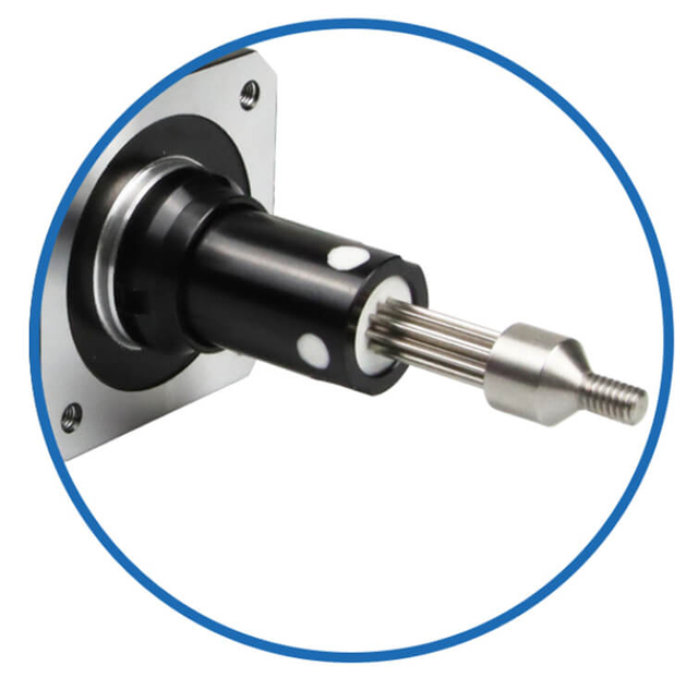
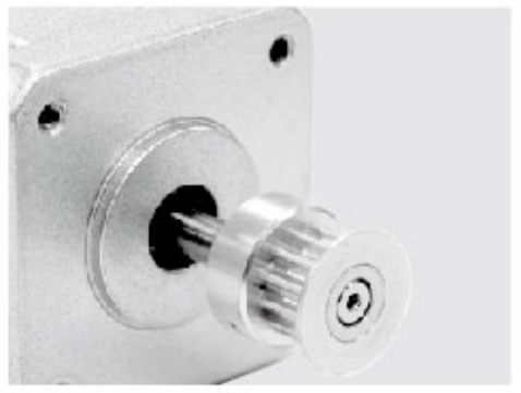
Optimize the Mechanical Output: Shaft, Gearbox, and Coupling Options
For robotic systems, optimizing the mechanical output of a stepper motor is just as important as selecting the motor type, frame size, or driver. Proper mechanical integration ensures smooth motion, high torque transmission, minimal backlash, and long-term reliability. This involves careful selection of the shaft type, gearbox, and coupling method to match your robotic system’s performance requirements.
The motor shaft is the primary interface between the stepper motor and the robotic load. Choosing the correct shaft type, diameter, length, and configuration is critical for torque transmission and mechanical stability.
Common shaft options for robotic applications:
Round Shaft – Standard option for simple couplings; easy to integrate with clamps or collars.
D-Cut Shaft – Flat surface ensures anti-slip connection for set-screw couplings; widely used in precision robotics.
Keyed Shaft – Incorporates a keyway for high-torque transmission; ideal for heavy-duty actuators.
Double Shaft – Provides output on both ends; one side can drive the load while the other drives an encoder or gearbox.
Hollow Shaft – Allows for pass-through applications, such as cabling or direct integration with a lead screw.
Shaft parameters to specify carefully:
Diameter and tolerance – Ensures proper fit with couplings and reduces wobble.
Length – Must accommodate couplings, gears, or pulleys without interference.
Surface finish and hardness – Reduces wear and improves coupling grip.
Axial and radial play – Minimizes backlash in precision robotics.
Selecting the right shaft reduces vibration, eliminates slippage, and improves repeatable positioning in multi-axis robotic systems.
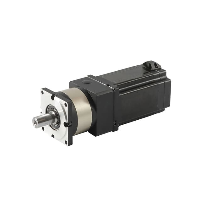
2) Gearbox Integration for Torque and Speed Optimization
A gearbox can dramatically improve a stepper motor’s torque output while reducing speed to match the robotic axis requirements. Gearboxes are essential when the robot must move heavy payloads, maintain precise position, or achieve higher torque density.
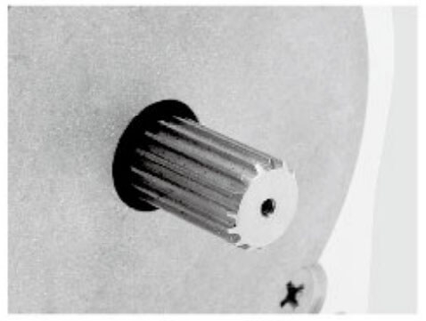
Common gearbox types used in robotics:
Planetary Gearbox – Compact, efficient, high torque, minimal backlash; widely used in robotic joints.
Worm Gearbox – Provides self-locking capabilities, useful for vertical lifting axes; moderate efficiency.
Spur Gear Reducer – Cost-effective, simple, but may have higher backlash; suitable for linear actuators.
Harmonic Drive – Extremely low backlash, high precision; ideal for high-end robotic arms.
Key gearbox selection considerations:
Reduction ratio – Matches motor speed to axis speed and improves torque.
Backlash – Should be minimized in precision robotics; harmonic drives are best for zero-backlash requirements.
Mechanical alignment – Flange, shaft, and mounting must match the gearbox interface.
Efficiency and heat – Some gear types generate heat under load; consider thermal limits.
Proper gearbox integration allows smaller stepper motors to drive larger robotic loads while maintaining precision and smooth motion.
3) Coupling Methods for Reliable Torque Transmission
Couplings connect the stepper motor shaft to the robotic load, gearbox, or linear actuator. Choosing the right coupling ensures efficient torque transfer, minimal vibration, and long life.
Common coupling types in robotics:
Rigid Coupling – Direct torque transfer with no elasticity; suitable for well-aligned axes with minimal vibration.
Flexible Coupling – Compensates for minor misalignment; reduces vibration and protects motor bearings.
Oldham Coupling – Allows lateral misalignment; excellent for modular robotic assemblies.
Jaw Coupling – Provides torque transmission with vibration damping; widely used in precision automation.
Bushing or Clamp Coupling – Simple and cost-effective; commonly used in light-duty robotic actuators.
Key coupling considerations:
Torque rating – Must handle peak load without slipping.
Misalignment tolerance – Flexible couplings prevent excessive bearing loads.
Vibration damping – Reduces resonance in robotic joints.
Assembly and maintenance – Should allow easy replacement or adjustment.
Using the correct coupling enhances motion smoothness, repeatability, and mechanical reliability.
4) Align Shaft, Gearbox, and Coupling for Precision Robotics
In robotics, even minor misalignment between the motor shaft, gearbox, and coupling can cause:
Best practices for alignment:
Use pilot diameters or precision flanges to center components.
Maintain tight tolerance fits between shafts and couplings.
Minimize axial and radial play across the assembly.
Consider modular design to allow for easy replacement without disturbing the robot structure.
Proper mechanical alignment ensures the robot operates smoothly at high speed and under dynamic load conditions.
5) Custom Mechanical Output Options for Robotics
For advanced robotic systems, custom solutions often provide significant benefits:
Integrated motor + gearbox + shaft assembly for compact modules
Double-ended shaft with encoder for closed-loop control
Custom D-cut or hollow shafts for specific robotic tool mounting
Motor with pre-attached planetary gearbox for vertical lifting or high-torque joints
Special coatings or materials for corrosion resistance or high-temperature environments
Custom mechanical outputs reduce assembly complexity, improve repeatability, and allow the stepper motor to perform optimally in its robotic application.
6) Summary: Key Mechanical Optimization Guidelines
Choose the correct shaft type for torque, coupling, and encoder integration.
Select a gearbox to match torque and speed requirements while minimizing backlash.
Use the right coupling to transfer torque efficiently and compensate for alignment errors.
Ensure precise alignment across motor, gearbox, and robotic load to avoid vibration or wear.
Consider custom solutions when standard shafts, gearboxes, or couplings cannot meet robotic performance targets.
By optimizing the mechanical output, we ensure the stepper motor delivers maximum torque, smooth motion, and reliable performance in robotic systems, from compact arms to industrial automation platforms.
Control Vibration, Noise, and Resonance in Robotic Motion
Robotics demands smooth motion. Stepper motors can produce resonance at specific speeds if not properly designed.
We improve motion quality by selecting:
Custom enhancements include:
These upgrades are critical for robotic inspection systems, collaborative robots, and medical robotics where motion feel matters.
Specify Environmental and Reliability Requirements
Robotic systems operate in many environments: clean rooms, warehouses, outdoor platforms, and factory floors. The stepper motor must survive the real conditions.
Key environmental factors:
operating temperature range
humidity and condensation
dust exposure
oil mist or chemical exposure
shock and vibration
continuous operation heat load
Customization options to improve reliability:
sealed housings
high-temperature winding insulation
corrosion-resistant shafts
IP-rated motor designs
special grease for bearings
reinforced lead wires and strain relief
For robotic systems running 24/7, thermal design and material selection are non-negotiable.
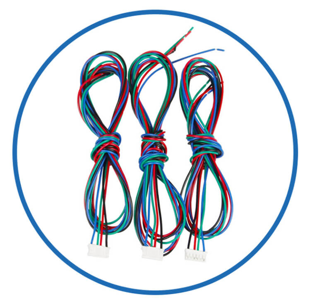
Choose the Right Connector, Cable, and Wiring Standard
In robotic systems, choosing the correct connector, cable, and wiring standard for a stepper motor is just as critical as selecting the motor type or frame size. Improper wiring can lead to signal interference, missed steps, mechanical failures, or costly downtime, especially in high-speed, multi-axis, or production robots. A well-planned wiring solution ensures reliability, ease of assembly, and long-term maintenance efficiency.
1) Determine the Electrical Requirements First
Before selecting connectors or cables, we must know the motor’s electrical specifications:
Phase current and voltage
Number of phases (typically bipolar or unipolar)
Encoder integration (if using closed-loop or integrated stepper motor)
Driver compatibility (microstepping or high-speed requirements)
Maximum current ripple or EMI tolerance
This ensures the cable and connector can safely carry current without overheating and avoid voltage drops that reduce motor performance.
2) Choose the Appropriate Connector Type
The connector must match the robot’s assembly and maintenance needs. Common connector types for stepper motors include:
JST / Molex / Hirose Connectors
DIN / Circular Connectors
Rugged and vibration-resistant
Common in industrial robotics
IP-rated versions available for dust or water exposure
Terminal Blocks or Flying Leads
Key considerations when choosing a connector:
Mechanical robustness – will it withstand robotic motion and vibrations?
Locking mechanism – prevents accidental disconnection
Ease of replacement – simplifies maintenance in multi-axis systems
Environmental protection – dust, moisture, or chemical exposure
For production robots, locking circular or industrial-grade connectors are often preferred for long-term reliability.
3) Select the Right Cable Type
The cable connects the stepper motor to the driver, and its quality affects signal integrity, motor response, and longevity.
Cable selection criteria:
Wire gauge: Must support rated motor current without excessive voltage drop
Shielding: Prevents EMI interference from nearby motors, encoders, or power lines
Flexibility: Needed for moving robotic arms or jointed mechanisms
Temperature rating: Must survive operating environment without insulation degradation
Length: Minimized to reduce resistance and inductive effects
Specialized options for robotics:
Torsion-rated robotic cables for rotating joints
Drag-chain compatible cables for multi-axis robotic arms
Shielded twisted pairs for encoder feedback or differential signaling
4) Optimize Wiring Layout for Multi-Axis Robots
Robots often have multiple stepper motors in close proximity. Poor wiring planning can cause electrical noise, signal crosstalk, and mechanical interference.
Best practices:
Separate power and encoder cables when possible
Use color-coded wires to simplify assembly and maintenance
Route cables along structured paths (cable chains, cable trays, or conduits)
Maintain bend radius per cable specification to prevent insulation damage
Minimize cable loops and twists to avoid EMI pickup
Proper wiring design improves repeatability and reduces downtime during production or field service.
Custom stepper motors can be optimized for robotic applications by integrating wiring considerations directly into the motor design:
Pre-attached, flex-rated cables to reduce assembly errors
Custom connector placement (side exit, rear exit, or angled) to fit tight spaces
Encapsulated leads or strain reliefs to prevent fatigue in moving joints
Shielded and twisted pairs built into the motor to improve signal integrity
Integrated wiring reduces the chance of installation errors and ensures consistent performance across multiple robotic units.
6) Environmental and Safety Considerations
Robotic systems may operate in demanding conditions. Wiring must withstand:
Temperature extremes (heat from motor or environment)
Vibration and shock (especially in mobile robots or heavy-duty arms)
Exposure to dust, oils, or chemicals
Electrical safety standards (UL, CE, or ISO compliance for industrial robots)
Selecting IP-rated connectors and high-grade insulation increases the motor and robot system’s lifetime while reducing maintenance costs.
7) Plan for Maintenance and Modular Replacement
Robotics often require modular maintenance for quick swap-outs. Wiring should facilitate:
Quick-disconnect connectors for fast motor replacement
Consistent pin labeling to prevent miswiring
Standardized cable lengths for predictable assembly
Redundant shielding in multi-axis robots to reduce failures
This approach reduces downtime in high-production robotic applications or collaborative robot labs.
8) Summary Checklist for Connector, Cable, and Wiring Standards
When specifying stepper motor wiring for robotics, confirm:
✅ Electrical compatibility with motor and driver
✅ Connector type suitable for vibration, space, and maintenance needs
✅ Cable gauge, flexibility, shielding, and length meet application requirements
✅ Wiring layout reduces EMI and crosstalk in multi-axis systems
✅ Integrated wiring options or strain reliefs for moving joints
✅ Environmental protection for dust, oil, moisture, and temperature
✅ Maintenance-friendly modular design for replacement or service
By carefully selecting connectors, cables, and wiring standards, we ensure robust, reliable, and repeatable robotic performance without unexpected failures or downtime.
Custom Stepper Motor Checklist for Robotic Systems
When integrating a custom stepper motor into a robotic system, careful planning and specification are critical. A misstep in design or selection can result in lost steps, vibration, reduced accuracy, overheating, or mechanical failures. This checklist ensures that every motor meets the performance, reliability, and meets the performance, reliability, and integration requirements of modern robotic systems.
1) Motion and Load Requirements
✅ Define the robotic axis load, including mass and inertia
✅ Specify acceleration, deceleration, and top speed
✅ Determine the duty cycle (continuous, intermittent, or peak load)
✅ Confirm positioning accuracy and repeatability required
✅ Identify if the motor must hold position under load (holding torque priority)
2) Motor Type and Control
✅ Select the appropriate stepper motor type (PM, VR, Hybrid, Closed-loop)
✅ Decide open-loop vs closed-loop based on load variability and precision
✅ Confirm step angle and microstepping capability for smooth motion
✅ Ensure compatibility with driver electronics (current, voltage, microstepping support)
3) Frame Size and Mounting Standard
✅ Verify frame size fits the robot’s mechanical envelope
✅ Confirm stack length for required torque without interfering with structure
✅ Match flange size, pilot diameter, and bolt pattern to brackets
✅ Determine shaft type, diameter, and length to interface with load or gearbox
✅ Evaluate shaft orientation and connector exit direction for assembly
4) Torque and Speed Specifications
✅ Calculate holding torque to resist static load
✅ Determine running torque at operating speed
✅ Include peak torque requirements for acceleration or shock loads
✅ Ensure torque margin for smooth, reliable motion
5) Electrical and Wiring Considerations
✅ Specify rated current, voltage, and inductance for driver compatibility
✅ Select connector type based on space, vibration resistance, and maintenance needs
✅ Choose cable type (shielded, flex-rated, torsion-rated)
✅ Ensure wiring layout avoids EMI, cross-talk, or mechanical interference
✅ Confirm encoder integration if using closed-loop or hybrid stepper
6) Mechanical Output Optimization
✅ Select shaft type (D-cut, keyed, hollow, or double shaft)
✅ Choose coupling method for torque transmission and misalignment compensation
✅ Integrate gearbox if torque or speed adjustment is needed
✅ Ensure proper alignment of shaft, gearbox, and coupling to minimize wear and vibration
7) Environmental and Reliability Factors
✅ Check operating temperature range for motor and insulation
✅ Verify resistance to dust, moisture, chemicals, or oil if relevant
✅ Confirm vibration and shock tolerance for robotic movement
✅ Choose IP-rated housing or sealed motors for harsh environments
✅ Ensure thermal design supports expected duty cycle
8) Manufacturing and Quality Assurance
✅ Specify bearing quality and tolerance
✅ Confirm shaft runout and axial play limits
✅ Require stator and rotor alignment precision
✅ Verify magnet and coil quality for consistent torque
✅ Ensure QC processes and batch traceability for repeatable performance
9) Assembly and Maintenance
✅ Confirm connector placement and cable routing for easy assembly
✅ Ensure modular motor replacement capability
✅ Include strain relief and flex-rated cables for moving joints
✅ Standardize pinout and labeling to reduce assembly errors
10) Final Integration Check
✅ Verify mechanical fit with robot axes, gearbox, and end-effectors
✅ Confirm electrical compatibility with drivers and control system
✅ Validate torque, speed, and precision in prototype testing
✅ Ensure thermal and environmental performance under expected conditions
✅ Document all specifications for repeatable mass production
A well-checked custom stepper motor ensures your robotic system achieves smooth motion, precise positioning, reliable operation, and long-term durability. Using this checklist reduces redesign risk and ensures consistent performance across multiple robotic units.
Final Recommendation: Build a Custom Stepper Motor Around the Robotic Axis
The best approach is to treat the motor as part of the robotic axis—not as a standalone component. A properly selected custom stepper motor for robotic systems improves torque stability, motion smoothness, assembly efficiency, and long-term reliability.
When we align mechanical integration, electrical performance, and manufacturing consistency, we achieve a robotic motion solution that performs predictably in real-world operation and scales cleanly into production.
Stepper Motor & Robotic System FAQs (OEM/ODM Customized)
What makes a stepper motor suitable for a robotic system?
A stepper motor must match torque demand, motion profile, control method, mechanical fit, and environment for reliable robotic performance.
What types of customized stepper motors are available for robotics?
Options include hybrid, permanent magnet, VR, closed-loop, geared, brake, hollow shaft, waterproof, linear, and integrated stepper motors.
What is the advantage of a hybrid stepper motor in a robotic motor application?
Hybrid stepper motors balance torque, precision, control stability, and scalability for most robotic axes.
When should I choose a closed-loop stepper motor for my robotic system?
When variable payloads, high speeds, vertical lifting, or error detection are critical, closed-loop motors improve accuracy and reliability.
Can OEM/ODM customized stepper motors integrate encoders for robotic feedback?
Yes — encoder feedback can be integrated to enable closed-loop control.
Are integrated stepper motors (motor + driver) suitable for robotics?
Yes — they simplify wiring and are ideal for compact modules like AGVs and mobile robots.
How does the factory customize stepper motor frame size for robotic applications?
Custom NEMA/metric frame sizes and mounting standards are defined based on robot structural constraints.
Can JKongmotor customize shaft design for robotic axis integration?
Yes — customized shaft geometries (round, D-cut, keyed, hollow) match actuator and coupling requirements.
Does OEM/ODM include custom cable exit orientation for robot wiring?
Yes — cable routing features and connector orientations are part of customization.
Why is selecting the right step angle important for robotic precision?
Step angle affects resolution; smaller angles and microstepping improve smoothness and motion quality.
Can JKongmotor adjust electrical parameters for robotic motor performance?
Yes — winding, current ratings, inductance, and thermal behavior can be engineered for specific robotic motion profiles.
What mechanical customizations are available from the factory for robotics?
Tailored mount flange details, pilot alignment features, and assembly tolerance control ensure repeatable production.
Is gearbox integration supported in OEM/ODM robotic stepper solutions?
Yes — planetary, worm, or other gearboxes can be customized and matched mechanically.
How does environmental protection customization help robotic systems?
Customized IP ratings, sealed housings, and specialized coatings improve durability in harsh environments.
Can the factory provide motors with optimized thermal performance for continuous robotic duty?
Yes — thermal management like low temperature rise and insulation upgrades are available.
Does JKongmotor support customized robotic motor integration with lead screws or actuators?
Yes — lead screws and actuator matching are available in OEM/ODM designs.
What role does torque margin play when selecting a robotic motor?
Adequate torque margin prevents stalling and ensures motion stability under dynamic loads.
Can the factory tailor robotic motors for high-speed motion profiles?
Yes — inductance, winding, and driver compatibility can be engineered for high-speed performance.
Is professional technical support part of OEM/ODM customization for robotic stepper motors?
Yes — co-engineering collaboration ensures designs meet system performance and production needs.
Do customized robotic stepper motor solutions enhance mass production consistency?
Yes — standardized mounting, electrical specs, and repeatable batch production improve reliability at scale.