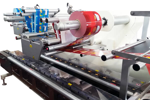
In modern packaging and production environments, wrapping machines rely heavily on high-precision motion control systems. At the heart of these systems are stepper motors, which provide accurate positioning, repeatable motion, stable torque, and precise synchronization across film feeding, sealing, cutting, and conveyor subsystems. Choosing the right stepper motor is not a matter of basic specification matching—it is a strategic engineering decision that directly influences machine reliability, wrapping quality, energy efficiency, maintenance cycles, and production output.
We present a comprehensive, application-focused guide on how to choose stepper motors for wrapping machines, covering load dynamics, torque calculation, speed profiling, microstepping resolution, thermal management, environmental protection, driver compatibility, and system optimization.
Understanding the Functional Role of Stepper Motors in Wrapping Machines
Wrapping machines are complex mechatronic systems combining continuous motion, intermittent indexing, high-speed film handling, and synchronized mechanical operations. Stepper motors are commonly deployed in:
Film feed and tension control systems
Sealing jaw actuation
Cutting and perforation modules
Product positioning tables
Labeling and print head drives
Rotary and linear indexing mechanisms
The advantage of stepper motors lies in their discrete step motion, deterministic positioning, high holding torque, and cost-effective closed-loop alternatives. For wrapping machines, this means consistent wrap length, uniform sealing pressure, precise alignment, and repeatable cycle timing.
Selecting the correct motor ensures smooth acceleration, minimal vibration, zero step loss, thermal stability, and long-term operational accuracy.
Comprehensive OEM & ODM Customized Hybrid Stepper Motor Solutions for Wrapping Machines
OEM + ODM Customized Stepper Motor Services & Capabilities
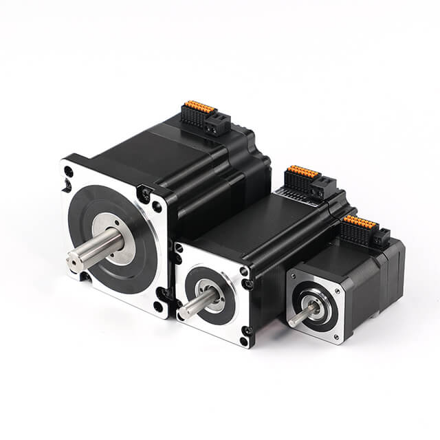
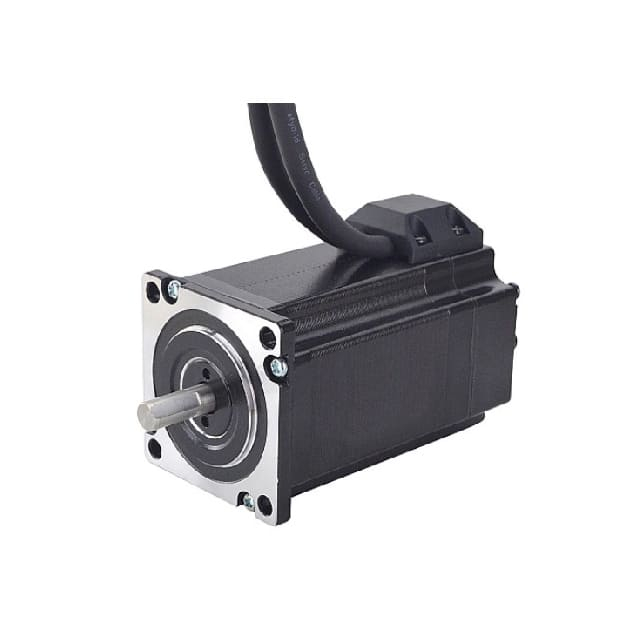
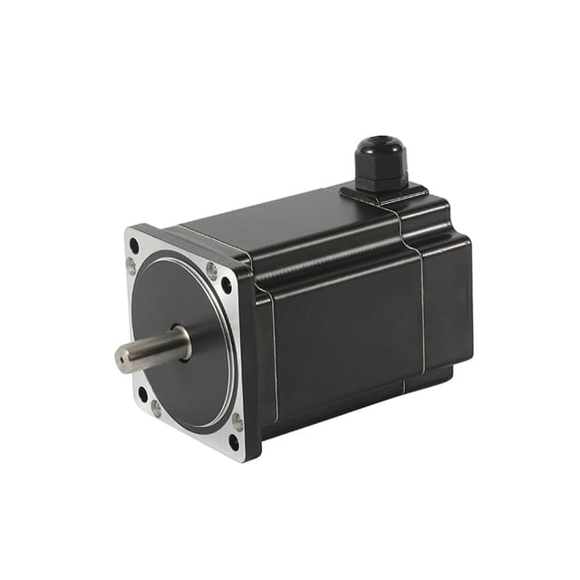
As a professional brushless dc motor manufacturer with 13 years in china, Jkongmotor offer various bldc motors with customized requirements, including 33 42 57 60 80 86 110 130mm, additionally, gearboxes, brakes, encoders, brushless motor drivers and integrated drivers are optional.
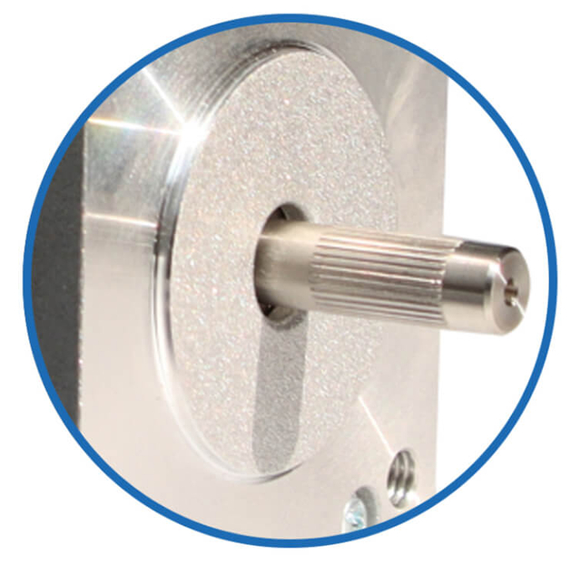
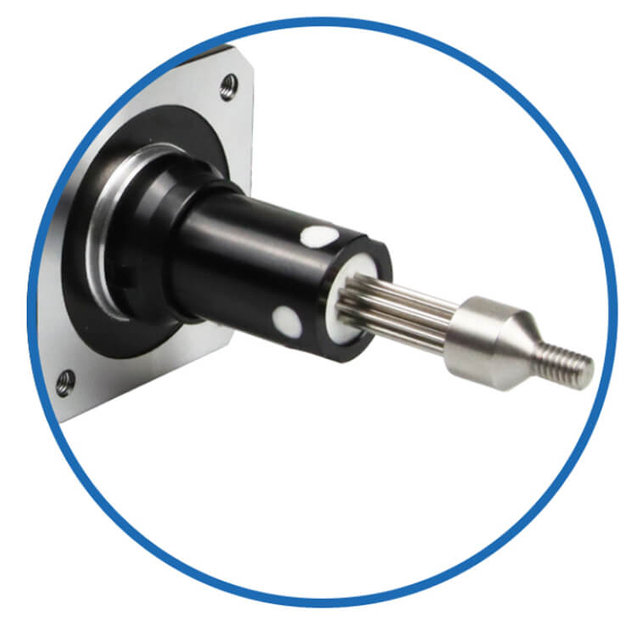
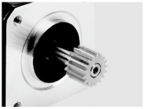
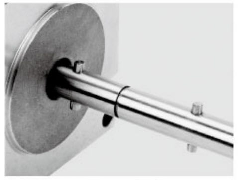
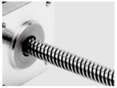
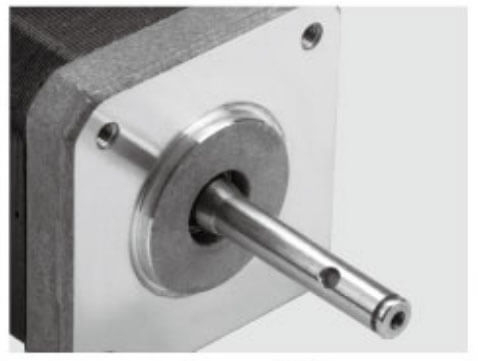
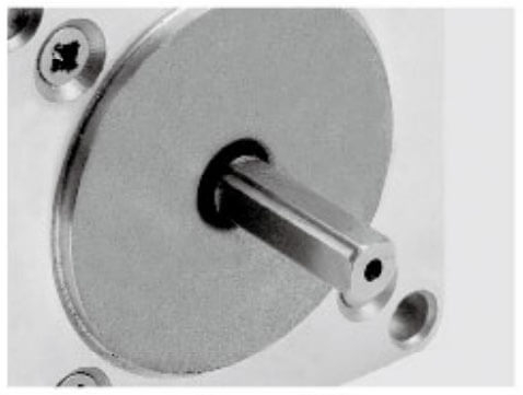
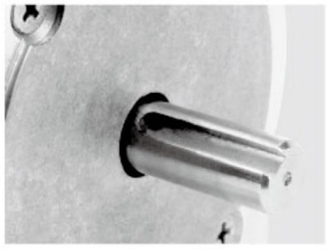
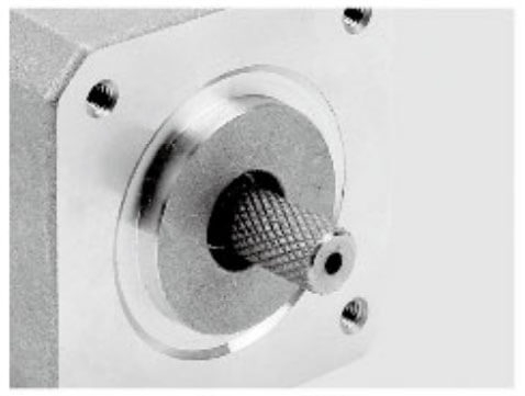
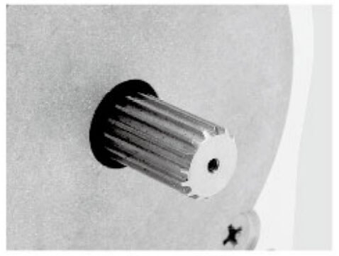
Jkongmotor offer many different shaft options for your motor as well as customizable shaft lengths to make the motor fit your application seamlessly.
Torque Engineering: Calculating Real Operating Requirements of OEM ODM Stepper Motors
In industrial automation, torque engineering is the foundation of every successful OEM and ODM stepper motor application. Whether the motor is driving a conveyor, indexing a rotary table, feeding packaging film, or positioning a robotic axis, incorrect torque estimation results in missed steps, overheating, vibration, premature failure, and unstable production output. Professional torque engineering goes far beyond reading a datasheet—it requires a system-level understanding of load behavior, motion dynamics, transmission efficiency, and real operating conditions.
This section presents a comprehensive engineering methodology to calculate the real operating torque requirements of OEM and ODM stepper motors with precision and confidence.
Understanding Torque in Practical Industrial Systems
Torque is not a single value; it is the sum of multiple interacting forces within a mechanical system. In OEM and ODM projects, torque must be analyzed across static, dynamic, and transient conditions.
Key torque categories include:
Load torque – the torque needed to move the working load
Inertial torque – the torque required to accelerate and decelerate mass
Friction torque – losses from bearings, belts, seals, and guides
Gravity torque – loads acting on vertical or inclined axes
Disturbance torque – irregular forces from cutting, sealing, pressing, or impacts
True operating torque is the combined real-time demand, not the motor’s rated holding torque.
Step One: Quantifying Load and Transmission Forces
Every torque calculation begins with a clear mechanical model.
For rotary systems:
Tload=F×r
Where:
T = torque (N·m)
F = applied force (N)
r = radius (m)
For linear systems using lead screws or belts, the conversion between force and torque must include pitch, efficiency, and mechanical reduction.
For lead screws:
T=(2π×η)/(F×p)
Where:
p = screw pitch
η = mechanical efficiency
OEM and ODM engineers must accurately measure:
Load mass
Rotational inertia
Pulley or gear radius
Transmission ratio
Mechanical efficiency
Even small miscalculations can shift torque demand by 30–60%, enough to destabilize the entire motion system.
Step Two: Inertial Torque and Dynamic Motion Demand
Stepper motors in industrial machines rarely run at constant speed. They are continuously starting, stopping, indexing, reversing, and synchronizing. In these conditions, inertial torque becomes dominant.
Tinertia=J×α
Where:
J = total reflected inertia (kg·m²)
α = angular acceleration (rad/s⊃2;)
Total inertia includes:
For belt drives and lead screws, inertia must be converted into equivalent rotational inertia.
In high-speed OEM machines, inertial torque can exceed load torque by 2–4 times, making it the primary design constraint.
Step Three: Frictional and Disturbance Losses
Real machines are not ideal mechanical systems. Torque is continuously consumed by:
Additionally, many OEM applications introduce disturbance torque, such as:
Cutting resistance
Sealing pressure
Punching impact
Film tension fluctuation
These forces are often nonlinear and time-varying, meaning they must be estimated conservatively.
Professional torque engineering always adds a measured friction coefficient or empirical load margin, never assumptions.
Step Four: Gravity and Orientation Compensation
In vertical or inclined axes, gravity introduces a constant torque component:
Tgravity=m×g×r
Where:
m = mass
g = gravitational acceleration
r = effective radius
Gravity torque determines:
In OEM lifting, dispensing, and Z-axis systems, gravity torque often defines the minimum motor frame size.
Step Five: Summation of Real Operating Torque
True operating torque is calculated as:
Ttotal=Tload+Tinertia+Tfriction+Tgravity+Tdisturbance
This value must then be evaluated under:
OEM and ODM stepper motors are selected based on available dynamic torque, not static holding torque.
Speed–Torque Curve Interpretation
Every stepper motor exhibits a declining torque curve as speed increases. Engineers must verify:
Available torque at operating RPM
Pull-out torque at peak acceleration
Stability through mid-band resonance zones
A motor that delivers 3 N·m holding torque may provide only 0.9 N·m at production speed. This mismatch is one of the most common causes of OEM project failure.
Applying Professional Safety Factors
No torque calculation is complete without engineering margin. OEM and ODM best practice applies:
1.3–1.5× safety factor for stable loads
1.6–2.2× safety factor for impact or cyclic loads
Higher margins for high-temperature or continuous-duty systems
Safety factors account for:
They ensure zero step loss, stable positioning, and thermal safety.
Thermal Constraints and Continuous Torque
Torque capability is directly linked to winding temperature. A stepper motor producing high torque at low speed may overheat under continuous duty.
OEM torque engineering therefore includes:
Motors are optimally selected to operate at 70–80% of rated current, maximizing lifespan while preserving torque margin.
Closed-Loop Stepper Systems and Torque Validation
Modern OEM and ODM designs increasingly use closed-loop stepper motors. Encoders allow:
Closed-loop architectures enable engineers to validate real torque demand during machine operation, refining motor selection with production data instead of theoretical estimates alone.
OEM and ODM Engineering Perspective
Torque engineering is not a datasheet exercise—it is a mechanical, electrical, and thermal system discipline. Properly calculated operating torque:
OEM and ODM stepper motor projects succeed when torque is engineered from real physics, real loads, and real duty cycles, not nominal assumptions.
When torque engineering is executed professionally, the stepper motor becomes not merely a component, but a precision motion foundation supporting the entire machine lifecycle.
Wrapping machines combine slow tension-controlled feeding with high-speed indexing and sealing cycles. Stepper motors must maintain torque stability across wide speed ranges.
Critical Speed Considerations
Motors with low rotor inertia and optimized magnetic circuits are better suited for fast acceleration and deceleration. Pairing the motor with a modern microstepping driver ensures smooth low-speed motion, reduced vibration, and quieter operation.
We prioritize motors that deliver flat torque curves, minimal mid-band resonance, and strong detent stability.
Precision Control: Step Angle, Microstepping, and Resolution of OEM ODM Stepper Motors
Precision control is the defining advantage of OEM and ODM stepper motor systems. Unlike conventional motors, stepper motors deliver deterministic, incremental motion, making them ideal for applications that demand exact positioning, synchronized movement, and repeatable accuracy. However, true precision is not achieved by motor selection alone—it results from the combined engineering of step angle, microstepping technology, control electronics, and mechanical transmission.
This section provides a comprehensive technical analysis of how step angle, microstepping, and resolution govern the real positioning capability of OEM and ODM stepper motors.
Fundamentals of Step Angle in Industrial Stepper Motors
The step angle is the basic mechanical increment of a stepper motor—the smallest full-step rotation the rotor can make when energized in standard stepping mode.
Common industrial step angles include:
1.8° per step (200 steps per revolution)
0.9° per step (400 steps per revolution)
Specialized designs: 1.2°, 7.5°, 15°, or custom angles for niche OEM requirements
A smaller step angle inherently increases native mechanical resolution, improving:
For OEM and ODM projects requiring high positional fidelity—such as optical equipment, semiconductor tooling, labeling machines, and medical automation—0.9° motors provide a superior mechanical foundation.
Mechanical Resolution and Positioning Capability
Mechanical resolution is defined as:
Resolution=360°Step Angle×Gear RatioResolution = \frac{360°}{Step\ Angle \times Gear\ Ratio}
Resolution=Step Angle×Gear Ratio360°
When combined with gearboxes, belts, or lead screws, the final system resolution can reach micron or sub-micron levels.
However, resolution must always be considered alongside:
Backlash
Elastic deformation
Transmission efficiency
Bearing compliance
OEM engineers focus not only on theoretical resolution but on effective resolution, which reflects real repeatable positioning under load.
Microstepping Technology and Motion Subdivision
Microstepping divides each full motor step into smaller electrical increments by precisely controlling current through the motor windings.
Typical microstepping ratios include:
1/2, 1/4, 1/8, 1/16
1/32, 1/64, 1/128, 1/256
A 1.8° motor at 1/16 microstepping achieves 3,200 steps per revolution.
A 0.9° motor at 1/32 microstepping achieves 12,800 steps per revolution.
Microstepping dramatically improves:
Low-speed smoothness
Vibration suppression
Acoustic noise reduction
Motion interpolation
For OEM and ODM machines performing film feeding, optical scanning, surface finishing, and micro-positioning, microstepping is essential for stable motion.
True Resolution vs. Command Resolution
It is critical to distinguish between:
Due to magnetic nonlinearity, detent torque, and load interaction, microsteps are not perfectly equal in size. While microstepping increases smoothness, it does not proportionally increase absolute accuracy.
OEM engineers typically treat microstepping as a motion quality enhancer, not a direct replacement for mechanical resolution. High-precision applications combine:
Smaller step angles
Precision gear reduction
Encoder feedback
Structural rigidity
This ensures repeatable positioning, not just finer command increments.
Impact of Microstepping on Torque and Stiffness
As microstepping increases, incremental torque per microstep decreases. While full-step torque remains unchanged, each microstep delivers a fraction of that torque.
This affects:
For OEM and ODM systems exposed to cutting forces, sealing pressure, or vibration, excessive microstepping without mechanical advantage may cause:
Professional designs balance microstepping ratios with gear reduction, closed-loop correction, or higher base torque motors.
Resolution Optimization Through Mechanical Transmission
Precision is often achieved more effectively through mechanical optimization than electronic subdivision.
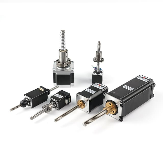
Examples include:
Planetary gearboxes for angular resolution multiplication
Lead screws for direct linear motion precision
Timing belts for synchronized multi-axis accuracy
Harmonic reducers for zero-backlash micro-positioning
By integrating stepper motors with properly engineered transmissions, OEM systems achieve:
Resolution engineering is therefore a mechatronic process, not an isolated motor decision.
Closed-Loop Stepper Systems and Resolution Validation
Closed-loop stepper motors incorporate encoders that continuously monitor rotor position. This enables:
Step loss elimination
Position error correction
Load-adaptive current control
Higher usable microstep precision
For OEM and ODM equipment where resolution directly impacts product quality—such as pick-and-place machines, vision-guided platforms, and medical instruments—closed-loop stepper systems transform microstepping from an approximation into a verifiable control strategy.
Encoders allow engineers to define true repeatable resolution, not just theoretical step counts.
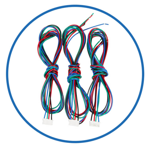
Electrical Control and Signal Integrity
Precision control also depends on:
OEM motion systems must ensure:
Clean differential pulse signals
High-frequency driver capability
Shielded cabling
Proper grounding architecture
Signal distortion at high microstep frequencies can degrade resolution more than mechanical limitations.
OEM and ODM Engineering Perspective
Precision control in stepper motor systems is the product of electromagnetic design, electronic control, and mechanical execution.
Correctly engineered step angle and microstepping strategies provide:
OEM and ODM projects succeed when resolution is engineered as a system parameter, integrating motor physics, transmission design, and control electronics into a unified motion solution.
When precision control is fully optimized, stepper motors deliver not just movement, but measurable, repeatable, industrial-grade positioning accuracy that forms the backbone of advanced automation.
Thermal Performance and Continuous Duty Reliability of OEM OEM ODM Stepper Motors
Wrapping machines often operate in 24/7 industrial production cycles. Stepper motors must deliver continuous torque without thermal overload.
Key Thermal Selection Factors
Oversized motors running at 70–80% rated current outperform undersized motors running at full load by providing:
Lower winding temperatures
Longer bearing life
Improved magnetic stability
Reduced demagnetization risk
We strongly emphasize thermal derating analysis when selecting motors for sealing and cutting stations where ambient temperatures are elevated.
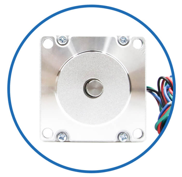
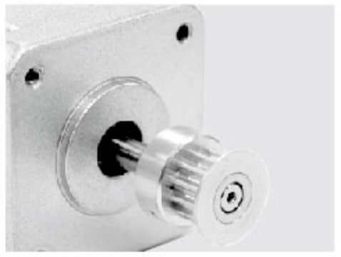
Mechanical Integration and Mounting Compatibility of OEM ODM Stepper Motors
Stepper motors must integrate seamlessly into the wrapping machine architecture.
Mechanical Selection Criteria
Standard frame sizes (NEMA 17, 23, 24, 34, 42)
Shaft diameter and length
Keyed or D-cut shafts
Flange compatibility
Bearing load ratings
Wrapping machines impose radial loads from belts, axial loads from lead screws, and torsional loads from gearboxes. Motors selected without adequate bearing specifications will suffer premature mechanical failure.
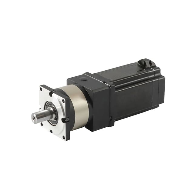
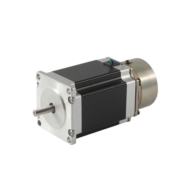
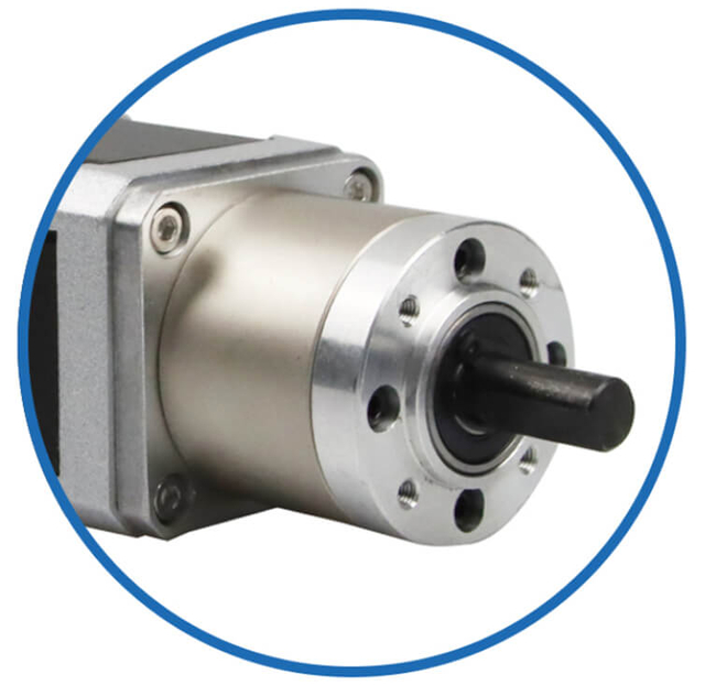
Where precision and durability are critical, we recommend gearbox-integrated stepper motors with planetary reducers, ensuring:
Higher output torque
Improved resolution
Reduced resonance
Extended service life
Environmental Protection and Industrial Durability of OEM ODM Stepper Motors
Wrapping machines frequently operate in environments exposed to:
Plastic dust
Adhesives and oils
Humidity
Cleaning chemicals
Temperature fluctuations
Stepper motors must therefore meet appropriate environmental and enclosure standards.
Protection and Build Quality Features
IP54–IP67 sealing options
Corrosion-resistant housings
High-temperature insulation coatings
Shielded cables and sealed connectors
For food and pharmaceutical wrapping machines, we prioritize washdown-rated motors, stainless steel shafts, and sealed bearings to maintain hygienic operation and regulatory compliance.
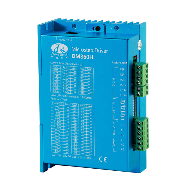
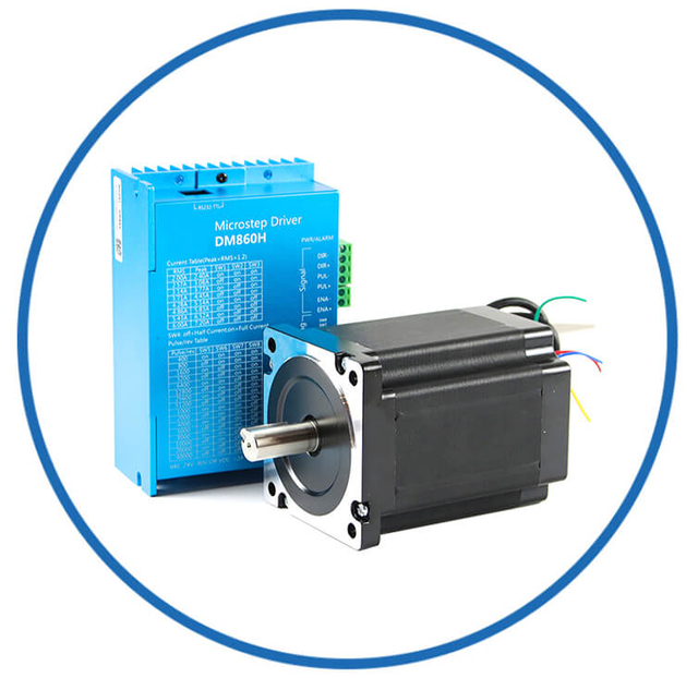
Driver Matching and Control Architecture of OEM OEM ODM Stepper Motors
A stepper motor’s performance is only as good as its driver and control electronics.
Essential Driver Characteristics
Constant-current regulation
High-frequency microstepping
Anti-resonance algorithms
Closed-loop feedback options
Fieldbus communication support
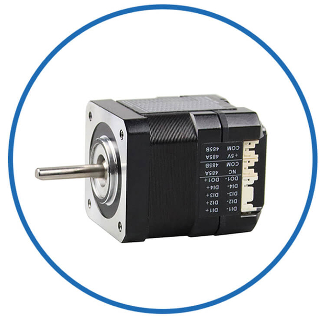
Modern wrapping machines increasingly integrate closed-loop stepper systems, combining the simplicity of stepper motors with encoder feedback, delivering:
We recommend selecting motors only after defining driver voltage, current capacity, control signals, and system bus architecture.
OEM ODM Stepper Motors’ Application-Specific Optimization for Wrapping Machines
Wrapping machines operate at the intersection of precision motion control, high-cycle durability, and continuous industrial throughput. In OEM and ODM manufacturing, stepper motors are not generic components; they are application-engineered actuators that must be optimized for each functional module within the wrapping system. Film feeding, product positioning, sealing, cutting, and indexing all impose distinct mechanical, thermal, and dynamic demands. Application-specific optimization ensures that stepper motors deliver stable torque, accurate positioning, smooth motion, and long-term reliability under real production conditions.
This section details how OEM and ODM stepper motors are professionally optimized for wrapping machine environments.
Understanding the Motion Architecture of Wrapping Machines
A modern wrapping machine is composed of multiple coordinated axes, each with its own motion profile:
Continuous low-speed film feeding
High-speed intermittent indexing
High-force sealing and cutting strokes
Synchronized rotary and linear positioning
Rapid acceleration and deceleration cycles
Each axis requires a stepper motor solution tailored for:
Torque curve shape
Rotor inertia
Step angle
Microstepping behavior
Thermal capacity
Environmental protection
Optimization begins by mapping the complete motion sequence, identifying peak loads, dwell times, shock forces, and long-duration holding conditions.
Film Feeding and Tension Control Modules
Film feeding systems demand exceptionally smooth, low-speed motion with consistent torque output to prevent:
Film stretching
Wrinkling
Misalignment
Registration errors
OEM-optimized stepper motors for film handling typically feature:
Low rotor inertia for rapid response
High microstepping compatibility
Strong low-speed torque linearity
Minimal detent torque ripple
These motors are often paired with:
This configuration delivers stable tension control, precise length metering, and vibration-free feeding, even at extremely low RPM.
Sealing Station Drive Optimization
Sealing units represent the highest mechanical stress zones of wrapping machines. Motors driving sealing jaws, rollers, or platens must withstand:
High peak forces
Elevated ambient temperatures
Rapid reciprocating motion
Continuous thermal loading
OEM and ODM stepper motors optimized for sealing stations emphasize:
High torque density
Robust stator thermal pathways
High-temperature insulation systems
Oversized bearings and shafts
Gear-assisted stepper motors are frequently applied to:
The result is consistent sealing pressure, uniform heat distribution, and precise jaw alignment, directly impacting package integrity.
Cutting, Perforation, and Knife Drives
Cutting mechanisms introduce impact loads and nonlinear resistance. Motors must respond instantly while maintaining positional repeatability.
Optimization strategies include:
High detent and holding torque
Reinforced rotor assemblies
Rigid flange structures
Encoded closed-loop operation
Closed-loop stepper motors are particularly valuable in knife drives, enabling:
Real-time stall detection
Automatic torque compensation
Zero-step-loss performance
This ensures accurate cut placement, reduced blade wear, and protection against mechanical shock.
Indexing Tables and Product Positioning Systems
Indexing and product positioning modules require high holding stability, precise stop accuracy, and fast synchronization with upstream and downstream processes.
OEM-optimized stepper motors in these subsystems feature:
High positional stiffness
Stable torque at mid-to-high speeds
Optimized rotor inertia matching
Planetary or harmonic gear integration
These motors maintain exact angular or linear positioning even when subjected to:
This ensures consistent wrap alignment, label registration, and product centering.
Environmental and Structural Customization
Wrapping machines operate in demanding production environments. OEM and ODM stepper motors are frequently customized for:
Environmental optimization includes:
Sealed housings and bearings
Corrosion-resistant shafts
IP-rated enclosures
High-performance cable insulation
Integrated strain relief designs
Structurally, motors may be customized with:
Extended shafts
Integrated couplings
Flange modifications
Embedded sensors
Compact form factors
This ensures seamless mechanical integration and long-term operational stability.
Thermal Optimization for Continuous Production
Wrapping machines often run multiple shifts with minimal downtime. Thermal engineering becomes critical.
OEM and ODM thermal optimization strategies include:
Enlarged stator mass for heat dissipation
Optimized winding resistance
Derated operating currents
Integrated heat sinking paths
Optional forced-air or conductive cooling
Thermally optimized motors maintain:
This directly supports production uptime and maintenance cost reduction.
Control Integration and System-Level Optimization
Stepper motors in wrapping machines do not operate in isolation. They are part of a coordinated motion ecosystem.
OEM and ODM optimization includes:
Driver matching for voltage and current curves
Anti-resonance tuning
Encoder resolution pairing
PLC and motion controller integration
Synchronization with servo and conveyor systems
Well-integrated motors deliver:
System-level optimization maximizes the true usable torque and precision of the motor, not merely its rated values.
Lifecycle Engineering and Reliability Enhancement
Application-specific optimization extends beyond performance to include service life engineering.
OEM and ODM stepper motors for wrapping machines are often designed with:
Oversized bearings
Reinforced shaft metallurgy
Moisture-resistant insulation
Long-life lubrication
Modular replacement architectures
These features reduce:
Ensuring stable long-term operation under repetitive, high-cycle industrial loads.
OEM and ODM Engineering Perspective
Optimizing stepper motors for wrapping machines is a mechatronic engineering discipline that unifies torque design, motion profiling, thermal management, structural customization, and control integration.
When application-specific optimization is executed correctly, stepper motors deliver:
OEM and ODM stepper motors, engineered specifically for wrapping machines, become core productivity components, transforming packaging equipment into high-precision, high-throughput industrial systems built for long-term operational excellence.
Lifecycle Cost, Efficiency, and Long-Term Stability of OEM ODM Stepper Motors
In industrial automation, the true value of OEM and ODM stepper motors is not measured by purchase price alone, but by lifecycle cost, operational efficiency, and long-term stability. Stepper motors deployed in production equipment must sustain millions of cycles, continuous thermal loading, fluctuating mechanical stress, and evolving process demands. Engineering decisions made at the design stage directly determine whether a motion system becomes a reliable productivity asset or a recurring maintenance liability.
This section examines how lifecycle-focused engineering transforms OEM and ODM stepper motors into high-value, long-term industrial solutions.
Lifecycle Cost as a Strategic Engineering Metric
Lifecycle cost encompasses all expenses incurred over the motor’s operational lifespan:
Acquisition and integration
Energy consumption
Maintenance and servicing
Downtime and lost production
Spare parts management
End-of-life replacement
In high-duty industrial systems, downtime and inefficiency far exceed initial hardware costs. Therefore, OEM and ODM motor engineering prioritizes operational continuity, durability, and predictable performance over minimal upfront pricing.
Motors selected purely on nameplate torque often result in:
Lifecycle-oriented designs prevent these outcomes through robust thermal margins, torque derating, and structural reinforcement.
Energy Efficiency and Electrical Optimization
While stepper motors are traditionally associated with holding torque consumption, modern OEM and ODM solutions employ advanced current regulation and adaptive drive strategies.
Efficiency optimization includes:
Low-resistance copper windings
Optimized magnetic circuits
High-voltage, low-current operation
Intelligent current reduction at idle
Closed-loop load-adaptive drive control
These strategies significantly reduce:
Heat generation
Power supply load
Cooling requirements
Insulation degradation
Over thousands of operating hours, improved electrical efficiency yields lower operating costs, greater thermal stability, and extended motor lifespan.
Thermal Stability and Its Impact on Longevity
Temperature is the single greatest determinant of stepper motor life. Every sustained rise in winding temperature accelerates:
OEM and ODM lifecycle engineering emphasizes:
Continuous torque derating
High-class insulation systems
Optimized stator-to-frame heat paths
Enlarged thermal mass
Optional conductive or forced-air cooling
Motors designed to operate well below maximum thermal limits deliver:
Stable torque output
Predictable electrical behavior
Longer bearing service life
Consistent positioning accuracy
Thermal discipline directly correlates with multi-year reliability in continuous-duty industrial equipment.
Mechanical Durability and Fatigue Resistance
Stepper motors in OEM machinery endure cyclic loading, vibration, shock forces, and axial stress. Mechanical fatigue is a silent lifecycle cost driver.
Long-term stability depends on:
Bearing selection and preload design
Shaft metallurgy and surface treatment
Rotor dynamic balance
Housing rigidity
Mounting interface precision
OEM and ODM motors engineered for lifecycle value often include:
Oversized industrial bearings
Reinforced shaft profiles
Optimized rotor support geometry
Improved sealing systems
Vibration-resistant assembly methods
These features significantly extend mean time between failures, reduce alignment degradation, and preserve motion accuracy over years of operation.
Control Stability and Performance Consistency
Lifecycle efficiency is not only mechanical—it is also control-level stability.
As motors age, electrical resistance changes, bearings loosen, and magnetic characteristics drift. OEM and ODM designs counteract these effects through:
Closed-loop stepper architectures
Encoder-based position verification
Adaptive current regulation
Integrated fault detection
These technologies maintain:
Zero-step-loss performance
Consistent torque delivery
Stable motion profiles
Early fault identification
Preventing small degradations from becoming production-critical failures.
Maintenance Economics and Serviceability
Lifecycle cost is heavily influenced by maintenance logistics.
OEM and ODM stepper motors optimized for serviceability feature:
Standardized mounting dimensions
Modular connector systems
Replaceable cable assemblies
Predictable wear profiles
Simplified spare part stocking
Such design decisions reduce:
Maintenance time
Technical skill barriers
Inventory complexity
Mean repair duration
Efficient service architecture ensures rapid recovery from faults with minimal production disruption.
Production Efficiency and Yield Stability
Long-term motor stability directly affects product consistency.
Degrading motion systems cause:
Inconsistent film feeding
Variable sealing pressure
Misaligned cuts
Registration drift
Increased scrap and rework
OEM and ODM motors engineered for lifecycle stability deliver:
These factors protect product quality, process repeatability, and brand reliability.
Total Cost of Ownership Optimization
Lifecycle-optimized stepper motors minimize total cost of ownership by:
Reducing energy waste
Extending maintenance intervals
Preventing unplanned downtime
Protecting machine accuracy
Supporting continuous improvement upgrades
While the initial motor investment may be marginally higher, the long-term outcome is:
Lower cumulative operating costs
Higher equipment availability
Predictable budgeting
Improved return on automation investment
OEM and ODM Engineering Perspective
Lifecycle cost, efficiency, and long-term stability are not secondary benefits—they are core design objectives in professional OEM and ODM stepper motor engineering.
When motors are engineered for lifecycle value, they provide:
OEM and ODM stepper motors developed with a lifecycle mindset become strategic industrial assets, supporting continuous operation, consistent product quality, and long-term profitability throughout the entire equipment lifespan.
Final Engineering Perspective
The correct stepper motor transforms a wrapping machine from a basic automation device into a precision industrial production system. By integrating accurate torque engineering, thermal analysis, motion profiling, environmental protection, and control compatibility, we ensure that each wrapping machine axis delivers consistent performance, high throughput, and long-term mechanical integrity.
Precision motor selection is not optional—it is the foundation of wrapping machine excellence.