Selecting the right stepper motor with brake for a vertical axis is a mission-critical decision in industrial automation, robotics, packaging machinery, medical devices, and lifting systems. Vertical motion introduces gravitational load, safety risk, back-driving force, and precision challenges that horizontal axes never face. We approach this topic from a system-engineering perspective, focusing on load security, motion stability, positioning accuracy, and long-term reliability.
This guide delivers a comprehensive, engineering-driven framework to ensure every vertical-axis design achieves safe holding, smooth lifting, precise stopping, and dependable load retention.
Vertical motion systems operate against gravity at all times. Without a brake, a powered-off stepper motor can allow the load to drop, drift, or back-drive, risking equipment damage, product loss, and operator safety.
A properly selected stepper motor with electromagnetic brake provides:
Fail-safe load holding during power loss
Instant shaft locking at stop
Improved positional stability
Protection for gearboxes and couplings
Compliance with industrial safety standards
In vertical axes, the brake is not optional—it is a primary safety component.
Choosing the correct brake structure is the foundation of a reliable vertical axis.
Power-Off (Fail-Safe) Brakes
These are the industry standard for vertical loads. The brake engages automatically when power is removed, locking the shaft mechanically. This ensures:
Power-On Brakes
Less common in vertical systems. These require power to engage and are generally unsuitable where gravity-driven motion exists.
Permanent Magnet vs. Spring-Applied Brakes
Spring-applied electromagnetic brakes dominate vertical axes due to high reliability and predictable torque output.
Permanent magnet brakes offer compact size but are more sensitive to temperature and wear.
For most industrial vertical axes, we recommend spring-applied, power-off electromagnetic brakes.
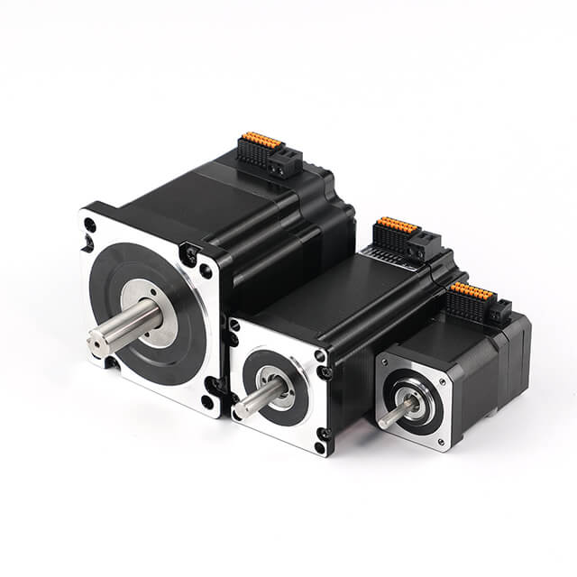
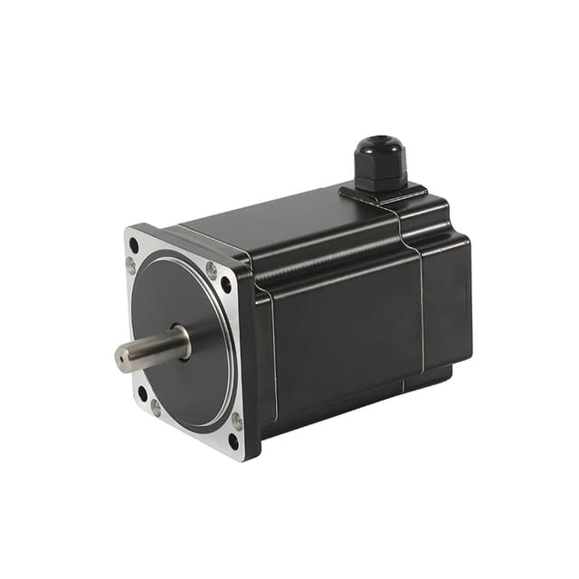
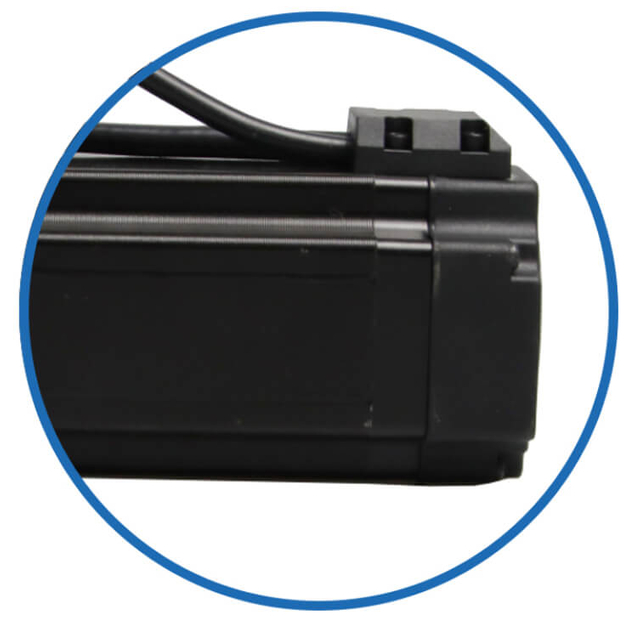
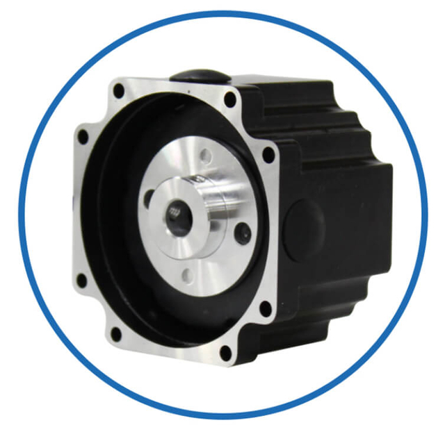
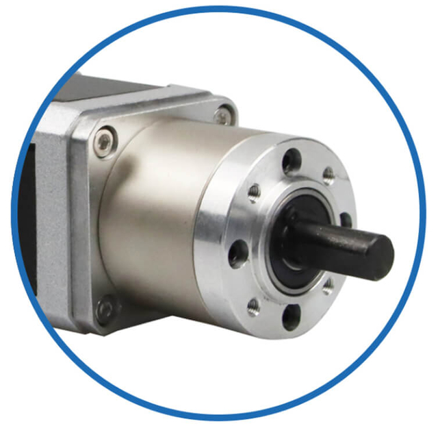
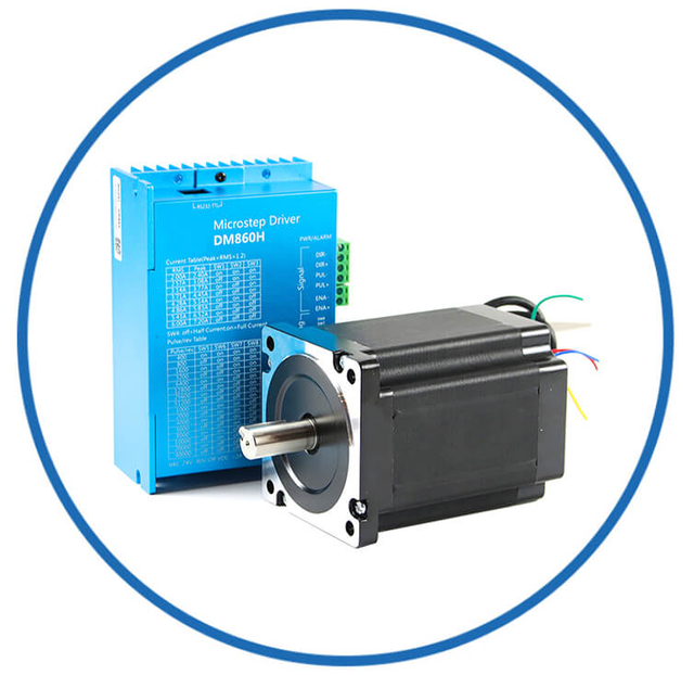
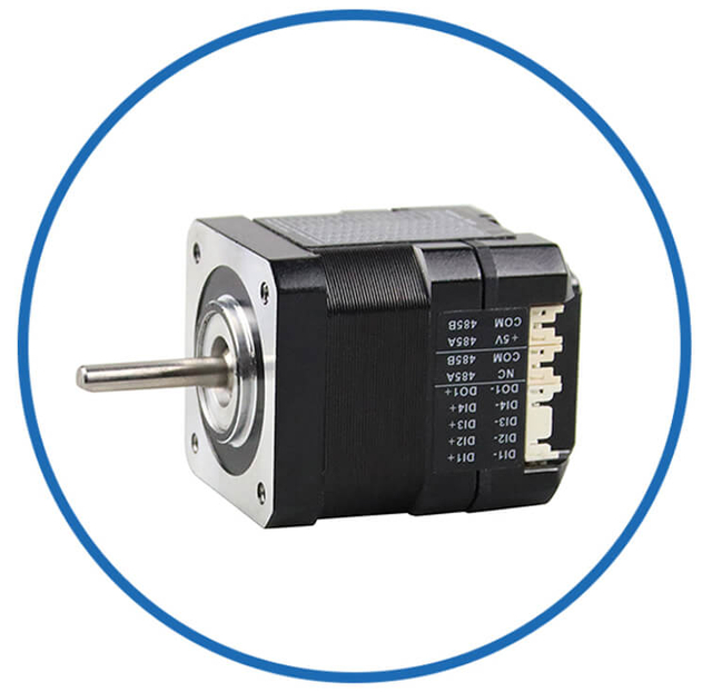
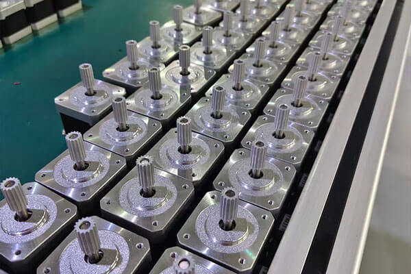
Customized Stepper Motor with Brake Service for the Vertical Axis Industry
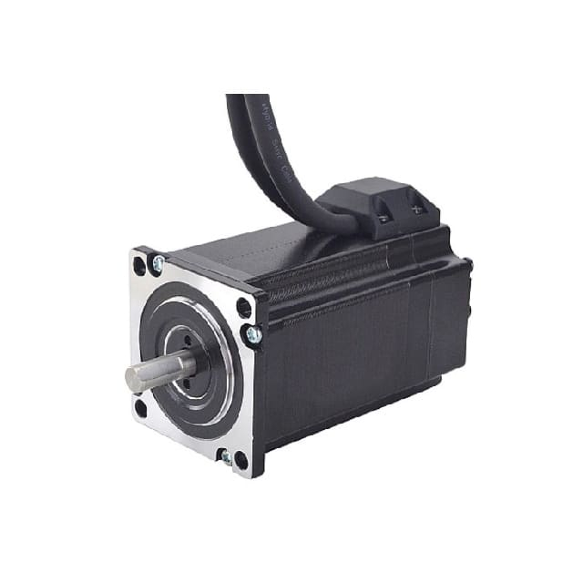
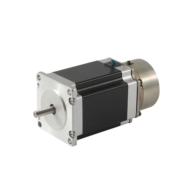
As a professional brushless dc motor manufacturer with 13 years in china, Jkongmotor offer various bldc motors with customized requirements, including 33 42 57 60 80 86 110 130mm, additionally, gearboxes, brakes, encoders, brushless motor drivers and integrated drivers are optional.
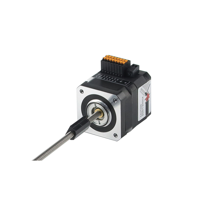
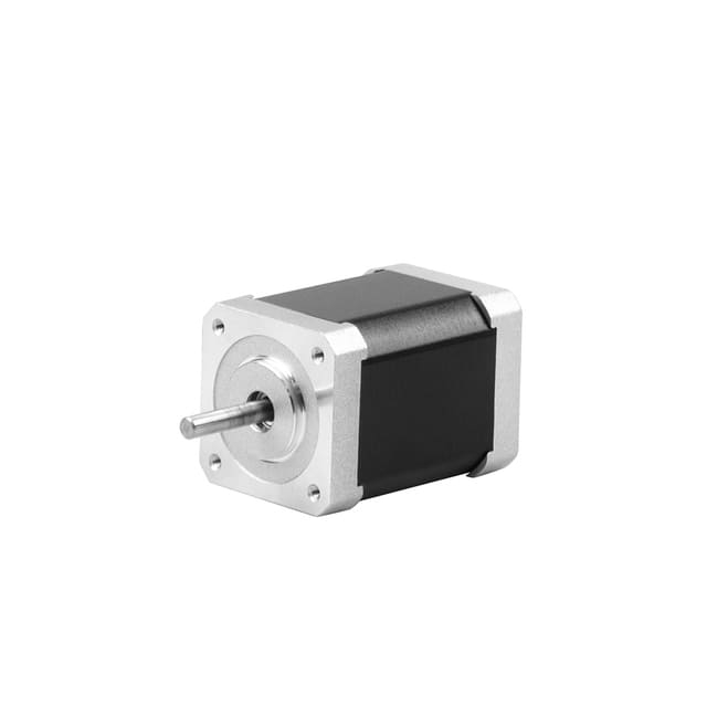
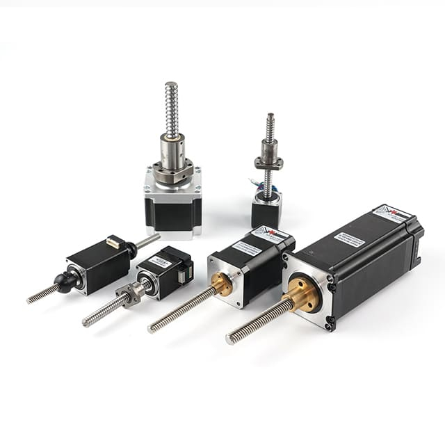
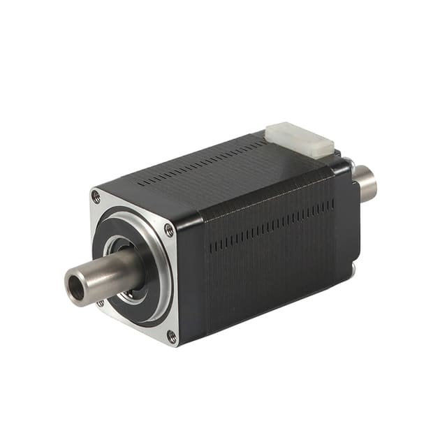
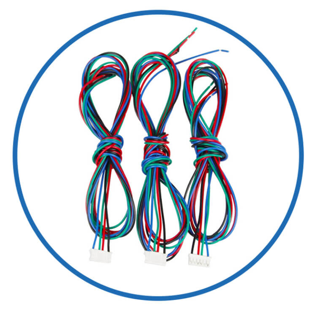
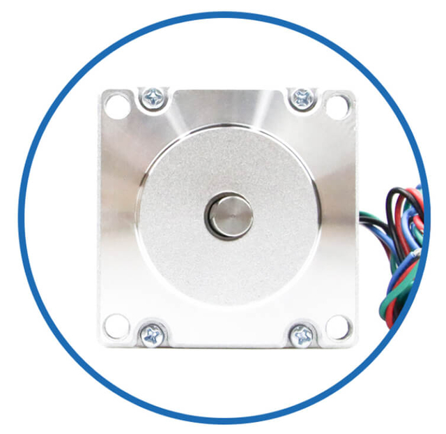
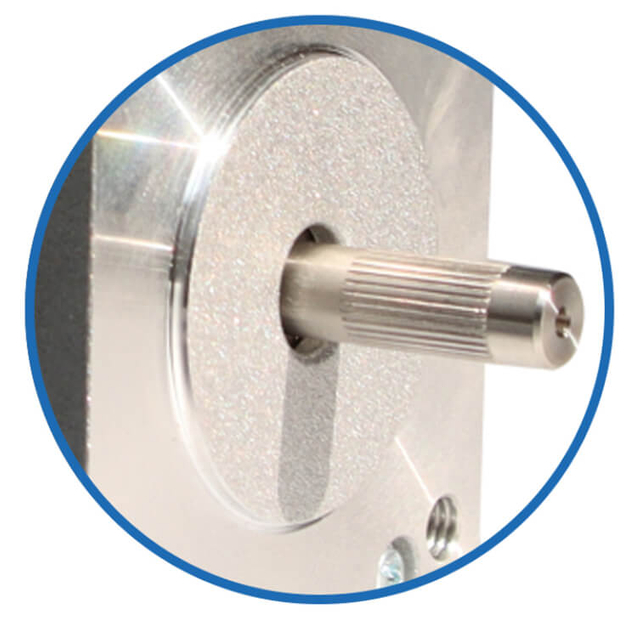
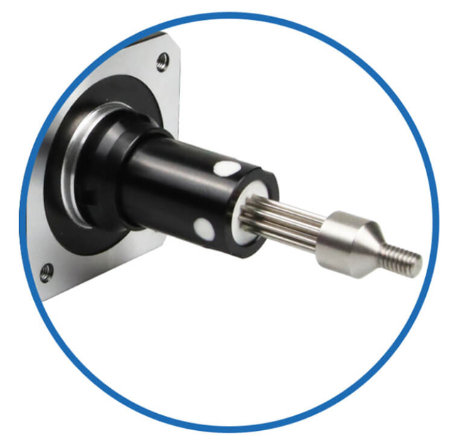
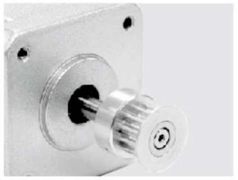
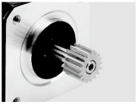
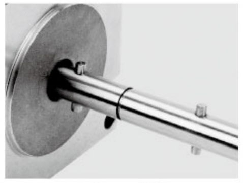
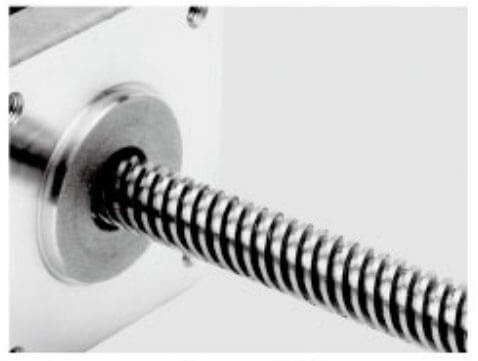
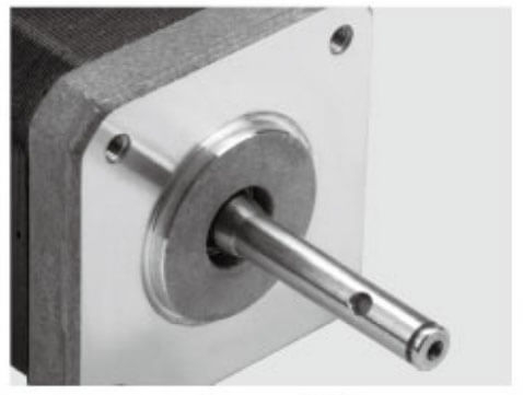
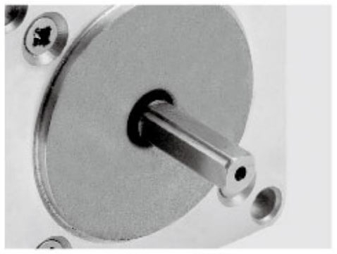
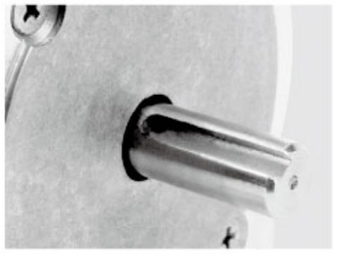
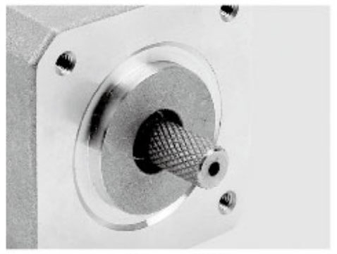
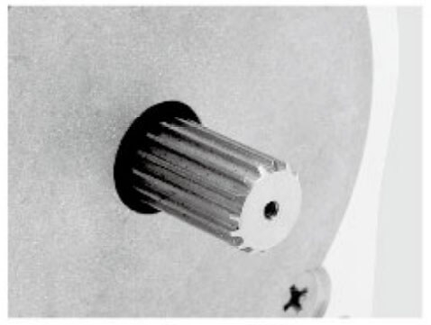
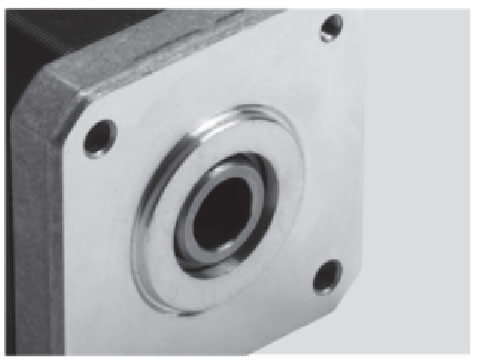
Customized Stepper Motor Shaft Options for Vertical Axis Industry Integration
Jkongmotor offer many different shaft options for your motor as well as customizable shaft lengths to make the motor fit your application seamlessly.
Accurate sizing begins with a precise torque calculation.
1. Static Holding Torque
The minimum brake torque must exceed the gravitational torque:
T = F × r
Where:
T = required holding torque
F = load force (mass × gravity)
r = effective pulley, screw, or gear radius
We always apply a safety factor of 1.5 to 2.5 to account for:
Load variation
Shock loads
Wear over time
Efficiency losses
2. Dynamic Torque During Motion
Vertical axes demand additional torque to overcome:
The stepper motor must deliver both motion torque and reserve holding torque, while the brake independently secures the load when stopped.
Selecting the correct brake holding torque for a vertical-axis stepper motor is not simply a mathematical exercise—it is a risk-based engineering decision. The brake is a safety device first and a mechanical component second. Its primary role is to secure the load under all conditions, including power loss, emergency stop, shock loading, and long-term wear.
We match brake holding torque to application risk by evaluating load characteristics, operational duty, human interaction, and system consequences of failure.
1. Start with True Gravitational Load Torque
The baseline is the static gravitational torque reflected to the motor shaft:
This value represents the absolute minimum brake torque. It is never the final selection.
2. Apply Risk-Based Safety Factors
Instead of using a single universal margin, we classify applications into risk tiers and assign brake torque accordingly.
Low-Risk Vertical Axes (1.5× Gravity Torque)
Examples:
Characteristics:
Recommendation:
Brake holding torque ≥ 150% of calculated gravity torque
Medium-Risk Industrial Axes (2.0× Gravity Torque)
Examples:
Packaging Z-axes
Assembly automation
3D printing platforms
CNC auxiliary lifts
Characteristics:
Recommendation:
Brake holding torque ≥ 200% of calculated gravity torque
High-Risk and Safety-Critical Axes (2.5× to 3.0× Gravity Torque)
Examples:
Characteristics:
Recommendation:
Brake holding torque ≥ 250%–300% of calculated gravity torque
In these systems, the brake must hold not only the static load, but also residual motion energy, gearbox elasticity, and worst-case fault conditions.
3. Account for Dynamic and Abnormal Conditions
Brake torque must exceed gravity torque plus the effects of:
Emergency deceleration
Back-driving from gearboxes
Elastic rebound from couplings or belts
Vertical oscillation
Unexpected load increases
We always include margins for:
A brake sized only for static load will fail prematurely in real vertical systems.
4. Consider Human Safety and Liability Exposure
Where people can stand beneath the load, brake torque becomes part of a functional safety strategy, not just motion control.
In these cases, we:
Increase torque margin
Prefer spring-applied power-off brakes
Validate with physical drop tests
Integrate dual-channel brake control logic
Higher holding torque directly reduces:
Micro-slip
Holding creep
Shaft back-driving
Failure escalation risk
5. Factor in Long-Term Degradation
Brake performance changes over time due to:
Friction surface wear
Temperature cycling
Contamination
Coil aging
We size brakes so that even at end-of-life, available holding torque still exceeds the maximum possible load torque.
This ensures:
6. Validate Through System-Level Testing
Brake torque matching is only complete after:
These confirm that selected holding torque is not only theoretically sufficient, but mechanically dependable.
Engineering Summary
Matching brake holding torque to application risk means:
Never selecting based on gravity torque alone
Scaling torque margins to safety exposure
Designing for abnormal and end-of-life conditions
Treating the brake as a primary safety element
A properly risk-matched brake transforms a vertical axis from a moving mechanism into a secure, fail-safe system.
Selecting the right stepper motor for vertical motion systems is fundamentally different from choosing one for horizontal axes. Gravity continuously acts on the load, introducing constant back-driving force, elevated holding requirements, and higher mechanical risk. A vertical-axis stepper motor must deliver not only precise positioning, but also stable lifting torque, thermal reliability, and long-term load security.
We approach motor selection as a system-level engineering process, not a catalog exercise.
1. Prioritize Real Working Torque, Not Rated Holding Torque
Rated holding torque is measured at standstill with full phase current. Vertical systems rarely operate under that condition.
We focus on:
The motor must overcome:
A vertical axis stepper motor should operate at no more than 50–60% of its usable torque curve, leaving margin for shock loads and long-term stability.
2. Select an Appropriate Frame Size and Stack Length
Vertical loads demand structural stiffness and thermal mass.
Common choices include:
NEMA 23 for light industrial Z-axes
NEMA 24 / 34 for automation, robotics, and lifting modules
Custom frame sizes for integrated vertical systems
Larger frames provide:
Higher continuous torque
Better heat dissipation
Stronger shafts
Improved bearing life
We avoid undersized motors, even when static torque calculations appear sufficient.
3. Match Rotor Inertia to the Vertical Load
Improper inertia matching leads to:
For vertical systems, the reflected load inertia should generally fall within 3:1 to 10:1 of motor rotor inertia, depending on speed and resolution requirements.
If the inertia ratio is too high, we incorporate:
Balanced inertia improves motion smoothness, holding stability, and brake engagement behavior.
4. Consider Closed-Loop Stepper Motors for Vertical Axes
Vertical motion is inherently unforgiving. Closed-loop stepper motors provide:
Real-time position feedback
Automatic current compensation
Stall detection
Improved low-speed torque utilization
This results in:
In medium to high-load vertical axes, we increasingly specify closed-loop stepper motors to protect both the machine and the brake system.
5. Evaluate Thermal Behavior Under Vertical Duty
Vertical axes often require:
This creates constant thermal stress.
We evaluate:
Winding temperature rise
Driver current mode
Brake heat transfer
Ambient conditions
Motor torque must be selected based on hot-state performance, not room-temperature data.
Thermal derating is essential to ensure:
Insulation life
Magnetic stability
Consistent torque output
Brake reliability
6. Shaft Strength and Bearing Capacity Matter
Vertical loads impose:
We verify:
A vertical axis stepper motor is a structural component, not only a torque source.
7. Optimize Step Angle, Resolution, and Microstepping
Vertical positioning accuracy depends on:
Step angle
Transmission ratio
Microstepping quality
Load stiffness
Higher resolution reduces:
We balance step resolution with torque demand to achieve:
Stable lift
Smooth settling
Accurate Z positioning
8. Integrate the Motor with Brake and Transmission as a Unit
The stepper motor cannot be chosen independently from:
Brake holding torque
Gearbox efficiency
Screw lead
Driver capability
We design the vertical axis as a mechanically coordinated system, ensuring:
Motor torque exceeds dynamic demand
Brake torque exceeds worst-case load
Transmission resists back-driving
Control logic synchronizes motor and brake
9. Validate with Real Operating Scenarios
Before final approval, we verify:
Maximum load lifting
Emergency stop under full load
Power-loss holding
Thermal steady-state behavior
Long-duration holding stability
This confirms that the selected stepper motor delivers not only motion, but structural confidence.
Engineering Summary
Choosing the right stepper motor for vertical motion requires focus on:
Real operating torque
Thermal margins
Inertia matching
Structural durability
Control stability
A correctly selected vertical-axis stepper motor provides:
Stable lifting
Precise positioning
Reduced brake stress
Long-term reliability
This transforms the vertical system from a motion mechanism into a secure, production-grade lifting axis.
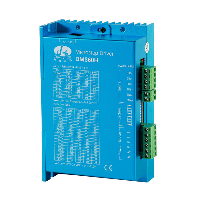
Brake Voltage, Response Time & Control Integration for Customized Stepper Motor with Brake in the Vertical Axis Industry
Brake selection must align with the control architecture.
Common Brake Voltages
Ensure the power supply can handle inrush current during brake release.
Release and Engagement Time
Critical for vertical axes:
We prioritize brakes with short response times and low residual torque.
Control Synchronization
Brake release must occur:
Interlocking through PLC or motion controller ensures zero load shock.
Vertical axes are often installed in demanding environments. Brake and motor must match:
We also assess:
For high-duty systems, we specify long-life friction materials and sealed brake housings.
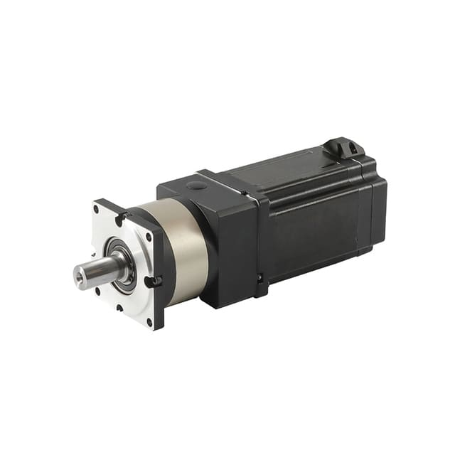
Gearbox and Transmission Considerations Affecting Customized Stepper Motor with Brake in Vertical Axis Industry
Many vertical axes incorporate:
Planetary gearboxes
Harmonic reducers
Ball screws
Timing belt drives
These components influence brake placement and torque requirements.
Key rules:
Brake should ideally be mounted on the motor shaft.
Back-driving torque must be evaluated at the brake location, not only at the load.
Gear efficiency and backlash directly affect holding stability.
We always verify that the brake torque exceeds reflected load torque after transmission losses.
Integrated stepper motors with built-in brakes represent a major evolution in vertical-axis and safety-critical motion systems. By combining the stepper motor, electromagnetic brake, and often the driver and controller into a single compact unit, these solutions dramatically improve reliability, simplify installation, and enhance load security—especially in applications where gravity, limited space, and system safety converge.
We specify integrated stepper motors with built-in brakes when performance consistency, rapid deployment, and long-term stability are design priorities.
1. What Defines an Integrated Stepper Motor with Brake
An integrated stepper motor with built-in brake incorporates:
A high-torque stepper motor
A spring-applied, power-off electromagnetic brake
Precision-aligned motor and brake hub
Optimized shaft, bearing, and housing design
Unified electrical interface
Many integrated models further combine:
This transforms the motor into a self-contained vertical-axis drive module.
Vertical systems demand:
Integrated brake motors deliver:
Instant mechanical load locking on power loss
Factory-matched brake torque and motor torque
Elimination of shaft misalignment risk
Predictable brake engagement behavior
Reduced transmission shock
This level of mechanical integration is difficult to achieve with separately mounted brakes.
3. Structural Advantages Over External Brake Assemblies
When brakes are added externally, system designers face:
Additional couplings
Increased shaft overhang
Tolerance stacking
Vibration sensitivity
Assembly variability
Integrated brake motors eliminate these issues by offering:
For vertical axes, this directly improves:
Holding stability
Stop repeatability
Brake service life
4. Electrical and Control Benefits
Integrated stepper motors with brakes typically feature:
Pre-wired brake coils
Optimized voltage and current matching
Dedicated brake release timing
Driver-brake interlock logic
This enables:
Clean start-up sequencing
Zero-load-drop release
Controlled emergency stops
Simplified PLC integration
The result is a vertical axis that behaves as a single controlled actuator rather than a collection of components.
5. Thermal Coordination and Reliability
In vertical applications, motors often hold torque for extended periods, generating continuous heat. Integrated designs allow manufacturers to:
Optimize heat flow between motor and brake
Match thermal class of insulation and friction material
Reduce thermal hotspots
Stabilize long-term brake torque
This coordinated thermal design significantly improves:
Brake wear resistance
Magnetic consistency
Holding reliability
Overall service life
6. Performance in Safety-Critical Environments
Integrated stepper motors with built-in brakes are widely used in:
Their advantages include:
High repeatability
Predictable stopping distance
Reduced installation errors
Easier functional safety validation
When human safety or high-value loads are involved, integration reduces system uncertainty.
Modern integrated brake motors increasingly include encoders and closed-loop control, providing:
Real-time load monitoring
Stall and slip detection
Automatic torque compensation
Lower operating temperatures
Higher usable torque range
For vertical axes, closed-loop integration enhances:
This shifts the vertical system from passive holding to actively managed safety.
8. Simplified Installation and Faster Commissioning
Integrated units reduce system complexity by eliminating:
This leads to:
For OEMs and system integrators, this means faster time-to-market and higher production consistency.
Integrated stepper motors with brakes can be tailored with:
This allows vertical systems to be designed as complete motion modules, rather than assembled subsystems.
We prioritize integrated brake motors when:
The axis is vertical
Load drop is unacceptable
Installation space is limited
Safety validation is required
Production consistency is critical
Long-term reliability is a priority
In these scenarios, integration directly translates to reduced risk and improved machine credibility.
Engineering Summary
Integrated stepper motors with built-in brakes provide:
Fail-safe vertical load holding
Superior mechanical alignment
Optimized thermal behavior
Simplified wiring and control
Higher long-term reliability
They are not merely motors with brakes—they are engineered vertical-axis actuators. When vertical stability, safety, and system integrity matter, integrated brake motors form the foundation of a secure, production-grade motion platform.
Thermal Design and Long-Term Reliability
In vertical-axis systems, thermal design is inseparable from long-term reliability. A stepper motor with brake may satisfy torque calculations on paper, yet still fail prematurely if heat is not managed correctly. Vertical applications are especially demanding because they often require continuous holding torque, frequent stop-and-hold cycles, and extended dwell times under load, all of which generate sustained thermal stress.
We treat thermal engineering as a primary design discipline, not a secondary check.
1. Why Vertical Axes Create Higher Thermal Stress
Unlike horizontal axes, vertical systems must constantly counter gravity. Even when stationary, the motor often remains energized to stabilize micro-movements and positioning accuracy. This leads to:
At the same time, the brake absorbs:
This combined thermal environment directly influences torque stability, insulation life, brake wear, and magnetic performance.
A vertical-axis stepper motor with brake generates heat from multiple sources:
Copper losses in motor windings
Iron losses during stepping
Driver switching losses
Friction heat during brake engagement
Coil heat in the brake itself
Long-term reliability depends on how effectively this heat is distributed, dissipated, and controlled.
3. Designing for Hot-State Torque, Not Cold Ratings
Motor datasheets often specify torque at 20–25°C. In vertical systems, steady-state temperatures can reach:
We therefore select motors based on:
The objective is to ensure that, even at maximum operating temperature, the motor still provides stable lifting torque and controlled braking behavior.
4. Brake Thermal Coordination
The brake is often the most thermally sensitive component. Excessive temperature can cause:
We coordinate brake and motor thermal design by verifying:
Compatible thermal classes
Sufficient brake torque margin
Heat conduction paths
Allowable surface temperatures
A thermally overloaded brake may hold initially but lose torque over time, leading to creep, micro-slip, and eventual load drop risk.
5. Housing Design and Heat Dissipation
Long-term reliability improves dramatically when heat is physically managed.
We evaluate:
Motor frame material and thickness
Surface area and cooling ribs
Mounting plate thermal conductivity
Airflow or convection environment
Enclosure ventilation
In high-duty vertical axes, we may incorporate:
Effective housing design stabilizes both motor windings and brake friction interfaces.
6. Duty Cycle and Holding Mode Optimization
Thermal load is strongly influenced by control strategy.
We optimize:
By transferring static load holding from the motor to the brake whenever possible, we significantly reduce:
Winding heat
Driver stress
Magnet aging
This division of labor between motor for motion and brake for holding is essential for long service life.
7. Long-Term Effects of Thermal Stress
If thermal design is neglected, vertical systems experience:
These failures often appear not as sudden breakdowns, but as:
Proper thermal design prevents these slow-developing but dangerous degradations.
8. Reliability Through Derating and Margin
We ensure long-term reliability by:
Operating motors below maximum current
Selecting higher thermal class insulation
Oversizing brake holding torque
Designing for worst-case ambient temperature
Thermal margin is directly correlated with:
Service life
Maintenance interval
Holding stability
Safety confidence
Every 10°C reduction in winding temperature can dramatically extend motor life.
9. Validation and Life Testing
Before deployment, we verify thermal reliability through:
Continuous-load temperature rise tests
Brake endurance cycling
Worst-case ambient trials
Power-loss holding simulations
Long-duration vertical parking tests
These confirm that thermal design supports not only performance, but endurance.
Engineering Summary
Thermal design is the silent determinant of success in vertical-axis stepper systems. It governs:
Torque consistency
Brake holding stability
Component aging
Safety margin
By engineering the motor, brake, housing, and control strategy as a coordinated thermal system, we transform a vertical axis from a functional mechanism into a long-life, production-grade, and safety-stable platform.
In vertical motion, heat management is reliability management.
Installation Best Practices for Vertical Axis Brakes
Correct installation preserves brake performance.
We emphasize:
Precision shaft alignment
Axial load management
Controlled air gap
Proper cable strain relief
Surge suppression on brake coil
Mechanical shock during installation is a major cause of premature brake failure.
Verification Testing Before Production
Before final deployment, we always perform:
These tests confirm the system’s true safety margin, not theoretical torque.
Common Vertical Axis Design Mistakes
Vertical axes are among the most failure-prone subsystems in motion control. Gravity never disengages, loads are constantly back-driven, and any design weakness is amplified over time. Most vertical-axis problems are not caused by defective components, but by system-level design mistakes made during motor, brake, and transmission selection.
Below are the most common and costly vertical-axis design errors—and the engineering logic behind avoiding them.
1. Sizing Only by Static Holding Torque
A frequent mistake is selecting a stepper motor or brake based solely on calculated gravity torque.
This ignores:
The result is a system that may hold initially, but slips, creeps, or fails under real operating conditions.
Correct practice is to size torque based on worst-case dynamic scenarios plus long-term margin, not static math alone.
2. Treating the Brake as Optional
Some vertical designs rely entirely on motor holding torque.
This creates major risks:
Load drop on power loss
Drift during driver faults
Thermal overload from continuous holding current
Accelerated bearing and magnet aging
A vertical axis without a fail-safe brake is structurally unsafe, regardless of motor size.
In gravity-loaded systems, the brake is a primary safety device, not an accessory.
3. Undersizing Motors to Reduce Cost or Size
Compactness and cost pressure often lead to undersized motors.
Consequences include:
Operation near pull-out torque
Excessive heat generation
Lost steps
Vertical oscillation
Reduced brake life due to shock loading
Vertical axes require motors selected for continuous, hot-state performance, not peak catalog ratings.
4. Ignoring Thermal Derating
Vertical axes commonly operate at elevated temperatures due to:
Constant holding current
Enclosed mounting
Brake heat conduction
Designs that fail to derate for temperature experience:
Thermal neglect is one of the leading causes of premature vertical-axis failure.
5. Poor Inertia Matching
High reflected inertia is often overlooked.
This causes:
When inertia ratios are ignored, even high-torque motors struggle to control vertical loads smoothly.
Proper inertia matching improves:
6. Incorrect Brake Torque Selection
Another frequent error is selecting a brake with:
This results in:
Brake torque must be matched to application risk, not just to calculated load.
7. Mounting and Alignment Neglect
External brakes and couplings introduce:
Shaft misalignment
Overhung loads
Bearing overload
Vibration sensitivity
Poor alignment accelerates:
Brake wear
Shaft fatigue
Encoder instability
Noise and heat
Vertical axes are mechanically unforgiving. Structural precision is not optional.
8. Unsynchronized Brake Control
Improper brake timing leads to:
The brake must:
Failure to coordinate brake logic turns a safety device into a mechanical hazard.
9. Overlooking Transmission Back-Driving
Ball screws, belts, and some gearboxes can back-drive under load.
Designers often assume:
High gear ratio equals self-locking
Motor detent torque is sufficient
Friction will prevent slip
These assumptions fail in real vertical systems.
Every vertical axis must be evaluated for true back-driving torque, reflected to the motor shaft and brake.
10. Skipping Worst-Case Validation Testing
Many vertical axes are deployed without:
This leaves hidden weaknesses undiscovered until field failure.
Vertical axes must be proven under:
Engineering Summary
The most common vertical-axis design mistakes stem from treating the system like a horizontal axis with gravity added. In reality, a vertical axis is a safety-critical lifting system.
Avoiding failure requires:
Risk-based torque sizing
Mandatory fail-safe braking
Thermal-driven motor selection
Proper inertia matching
Coordinated control logic
Full-scenario validation
Correct vertical-axis design transforms gravity from a threat into a controlled engineering parameter.
Future-Proofing Vertical Axis Systems
Vertical-axis systems are no longer simple lifting mechanisms. They are evolving into intelligent, safety-critical motion platforms that must operate reliably across longer service lives, higher performance expectations, and rapidly changing automation environments. Future-proofing a vertical axis means designing it not only to work today, but to adapt, scale, and remain compliant tomorrow.
We future-proof vertical systems by integrating mechanical resilience, control intelligence, and upgrade readiness into the foundation of the design.
1. Designing Beyond Today’s Load Requirements
A common limitation of legacy vertical axes is that they are optimized too tightly for a single load condition. Future-ready designs account for:
Tooling changes
Payload increases
Higher duty cycles
Process upgrades
We select motors, brakes, and transmissions with intentional performance headroom, ensuring that future modifications do not push the system into thermal or mechanical instability.
Reserve capacity is not waste—it is insurance against redesign.
2. Transitioning Toward Closed-Loop Stepper Technology
Closed-loop stepper systems are rapidly becoming the vertical-axis standard.
They provide:
Real-time position verification
Automatic torque compensation
Load anomaly detection
Stall and slip diagnostics
Reduced operating temperatures
This intelligence layer future-proofs vertical axes by enabling:
As automation shifts toward data-driven control, closed-loop capability becomes a long-term architectural advantage.
3. Integrating Smart Brake Management
Traditional brakes are passive. Future-proof vertical axes employ actively managed braking systems.
This includes:
Controlled release sequencing
Engagement health monitoring
Coil temperature supervision
Cycle count tracking
Smart brake integration enables:
This transforms the brake from a static safety device into a monitored functional component.
4. Mechanical Modularity and Upgrade Paths
Future-ready vertical axes are designed as modular assemblies, allowing:
Motor replacement without structural redesign
Brake torque upgrades
Encoder or gearbox integration
Driver and controller migration
Key design strategies include:
Standardized mounting interfaces
Flexible shaft and coupling options
Space reservation for future components
Scalable control architecture
This protects capital investment and supports evolving performance demands.
5. Designing for Data and Connectivity
Modern production environments demand more than motion. They demand information.
Future-proof vertical axes support:
These capabilities enable:
A vertical axis that reports its health becomes a managed asset rather than a hidden risk.
6. Enhancing Safety Architecture
Future compliance standards increasingly emphasize:
Functional safety integration
Redundant monitoring
Documented fault response
Controlled energy dissipation
Vertical axes must evolve from single-layer protection to systematic safety architecture, incorporating:
This ensures that vertical motion systems remain certifiable as regulations tighten.
7. Preparing for Higher Performance Demands
Future automation trends push vertical axes toward:
To accommodate this, we design for:
Improved inertia ratios
Higher thermal capacity
Precision bearings
Advanced motion profiles
A future-proof vertical axis can increase speed and precision without compromising stability.
8. Long-Term Thermal and Reliability Engineering
As production uptime expectations rise, vertical systems must sustain:
Future-proofing therefore requires:
Conservative thermal design
Brake derating strategies
Material aging analysis
Life-cycle endurance testing
Reliability becomes a designed feature, not a statistical outcome.
9. Validation with Forward-Looking Scenarios
Instead of validating only current operating points, we test for:
Maximum plausible future load
Elevated ambient environments
Extended holding durations
Increased emergency stop frequency
This ensures that the system remains stable under tomorrow’s worst cases, not only today’s.
Engineering Summary
Future-proofing vertical axis systems means shifting from component selection to platform engineering.
A future-ready vertical axis is:
Thermally resilient
Intelligently monitored
Safety-integrated
Modular and scalable
Performance-upgradable
By embedding adaptability, diagnostics, and margin into the design, vertical axes evolve from fixed mechanisms into long-term automation assets capable of meeting both present demands and future challenges.
Conclusion: Engineering a Secure and Stable Vertical Axis
Choosing a stepper motor with brake for a vertical axis is a system-level engineering task that blends mechanics, electronics, safety, and motion control. When properly selected, the result is:
A correctly engineered vertical axis becomes not just functional, but structurally dependable.
1. What is a customized stepper motor with brake and why is it important for the vertical axis industry?
A customized stepper motor with brake combines precision motion control with a fail-safe braking system. In vertical axes, where gravity constantly acts on the load, the brake prevents unwanted motion or load drop when power is lost, making it essential for safety and stability.
2. How does the brake mechanism work in a stepper motor for vertical systems?
In vertical applications, spring-applied, power-off brakes engage automatically when power is removed, mechanically locking the shaft and preventing the load from falling or drifting.
3. Why can’t I use a standard stepper motor without a brake in the vertical axis industry?
Without a brake, vertical systems risk back-driving or load drop during power failures or emergency stops, which can lead to equipment damage or safety hazards. The brake is treated as a primary safety component, not optional.
4. How do I calculate the required brake holding torque for a vertical axis application?
Brake torque is based on gravitational load torque (mass × gravity × effective radius) and must include safety margins depending on application risk. Higher risk applications require larger holding torque multiples of the calculated gravity torque.
5. What customization options are available for stepper motors with brakes?
Manufacturers can tailor brake torque, frame size, gearboxes, encoders, integrated drivers, shaft dimensions, environmental protection (e.g., IP rating), and control interfaces to match specific vertical axis requirements.
6. Should I consider closed-loop stepper motors for vertical applications?
Yes. Closed-loop stepper motors add real-time position feedback and torque compensation, reducing missed steps, improving low-speed torque utilization, and enhancing safety in vertical load handling.
7. What motor frame sizes are recommended for vertical axis systems?
Typical recommendations include NEMA 23 for light industrial Z-axes, and larger sizes like NEMA 24 or NEMA 34 for heavier automation, robotic lifting, or continuous duty vertical systems, ensuring structural strength and thermal performance.
8. How does thermal performance affect vertical axis stepper motors with brakes?
Vertical systems often hold loads for extended periods, generating heat from motors and brakes. Proper thermal design and derating ensure long-term torque stability and brake reliability.
9. What installation practices are critical for vertical axis brakes?
Correct shaft alignment, axial load management, controlled brake air gap, cable strain relief, and surge protection for brake coils are essential to preserve brake performance and long-term reliability.
10. When should I choose an integrated stepper motor with built-in brake for a vertical axis system?
Integrated solutions (motor, brake, and often driver/encoder in one unit) are preferable when installation space is limited, safety certification is required, long-term reliability is critical, and simplified wiring or predictable performance is desired.