Modern inspection equipment depends on precision motion, repeatability, and absolute reliability. From machine vision platforms and automated optical inspection systems to metrology stations, semiconductor testers, and non-destructive testing devices, motion control performance directly defines inspection accuracy. We select a stepper motor not as a commodity, but as a core functional component that determines system resolution, stability, throughput, and lifetime.
In this in-depth guide, we present a structured, engineering-focused framework for choosing the optimal stepper motor for inspection equipment, covering mechanical, electrical, environmental, and application-level considerations.
Inspection equipment imposes distinctive motion requirements that separate it from general automation. We typically encounter:
Micron-level positioning accuracy
Consistent low-speed stability
High repeatability over millions of cycles
Minimal vibration and acoustic noise
Compatibility with vision and sensing systems
We evaluate motors not only by headline torque, but by their ability to maintain precise incremental motion, smooth scanning, and stable dwell positioning under real inspection loads.
Selecting the Best OEM/ODM Customized Stepper Motor Type (Focus on Hybrid)
Choosing the correct stepper motor type is a foundational decision when designing or upgrading inspection equipment. The motor architecture directly influences positioning accuracy, torque stability, vibration behavior, thermal performance, and system lifespan. We do not select a stepper motor solely by size or torque rating; we evaluate its electromagnetic structure and motion characteristics to ensure it aligns precisely with inspection-grade requirements.
Below, we detail the three principal stepper motor types and define how each performs within professional inspection systems.
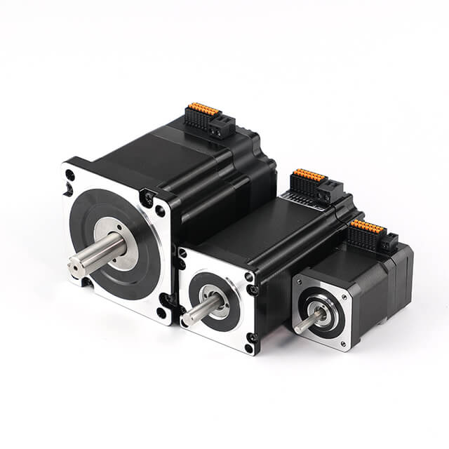
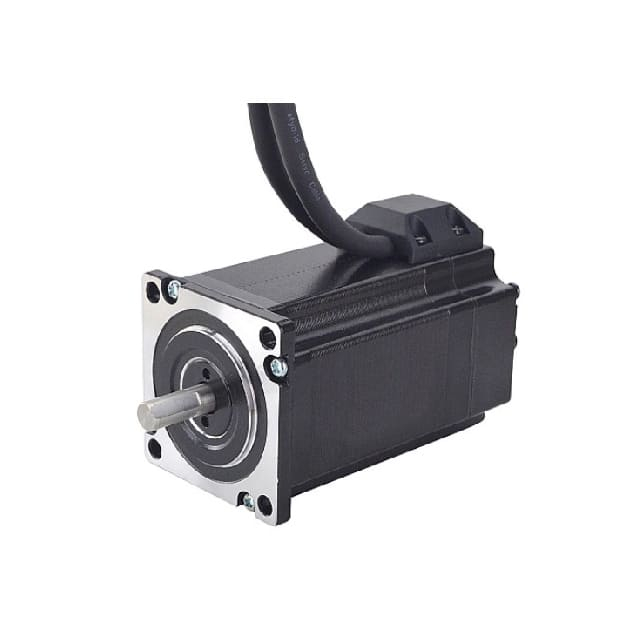
Comprehensive OEM & ODM Customized Hybrid Stepper Motor Solutions for Inspection Equipments
OEM + ODM Customized Stepper Motor Services & Capabilities
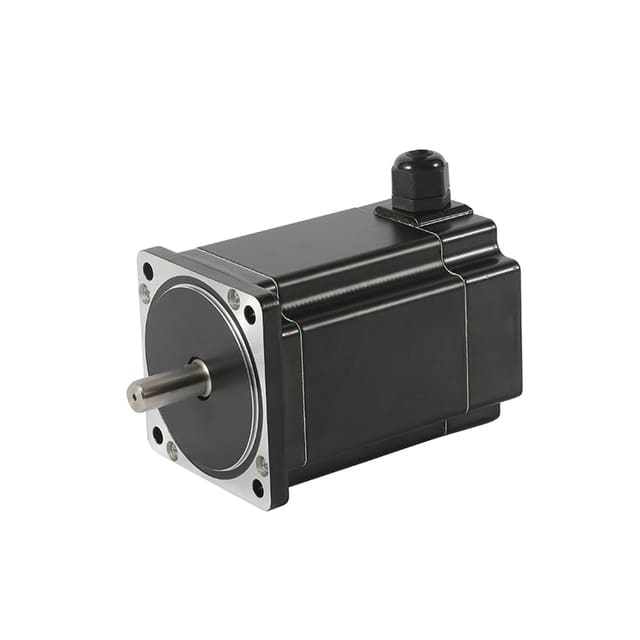
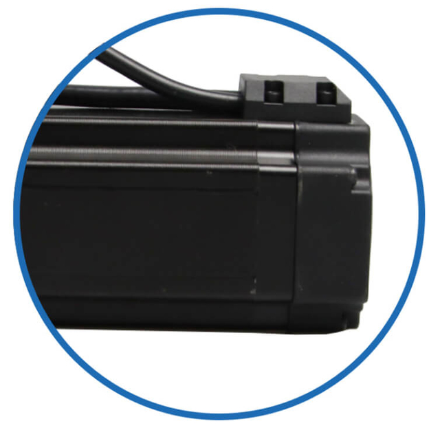
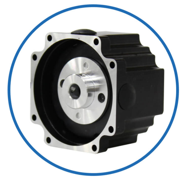
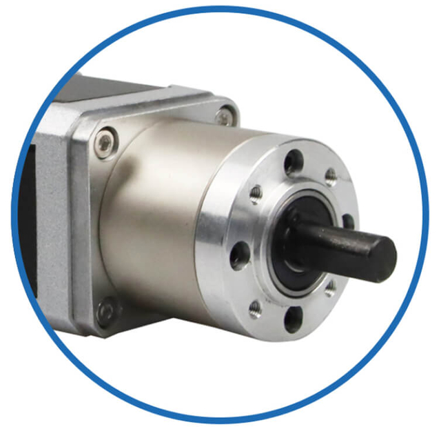
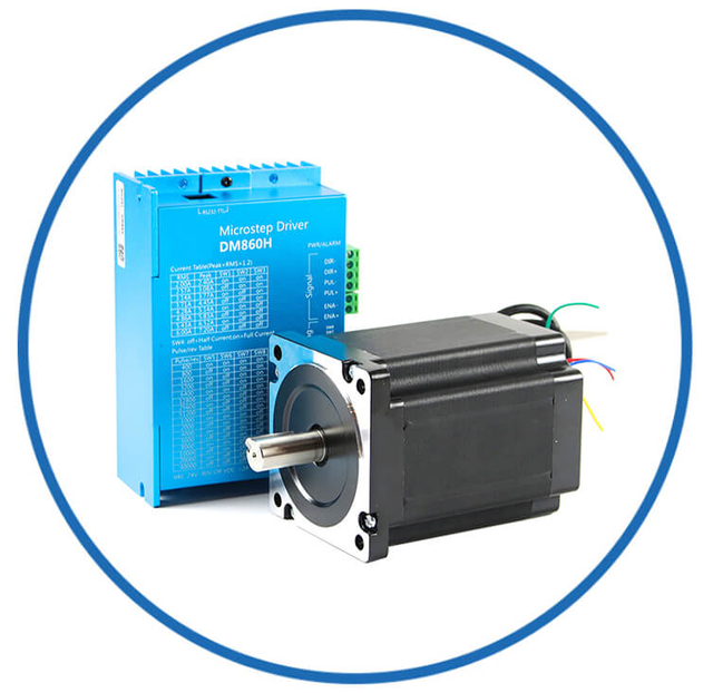
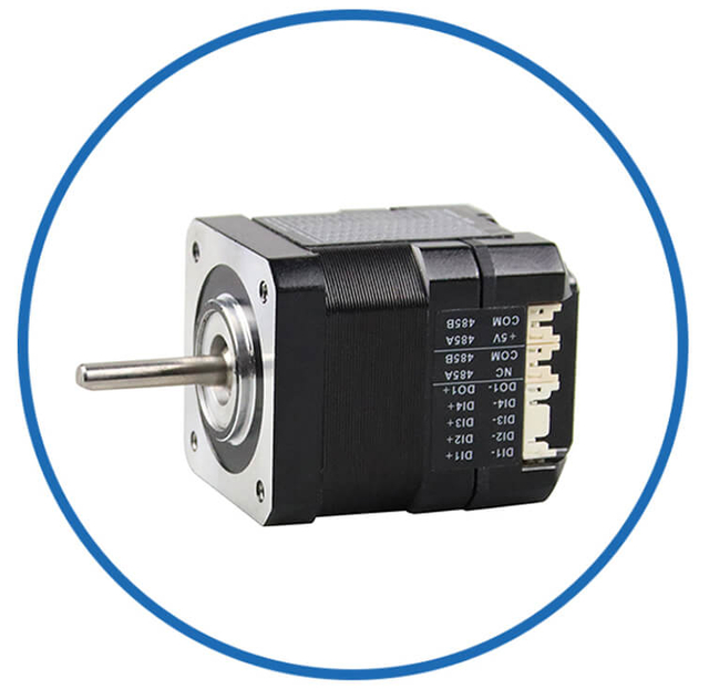
As a professional brushless dc motor manufacturer with 13 years in china, Jkongmotor offer various bldc motors with customized requirements, including 33 42 57 60 80 86 110 130mm, additionally, gearboxes, brakes, encoders, brushless motor drivers and integrated drivers are optional.
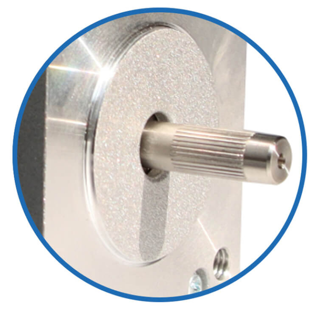
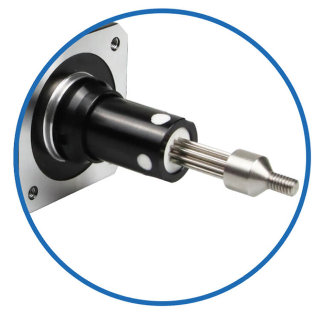
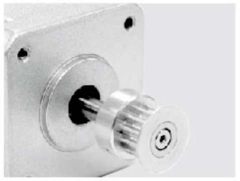
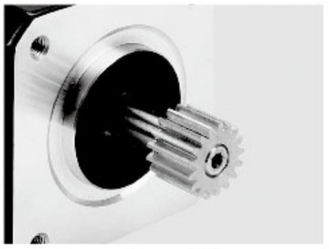
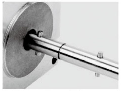
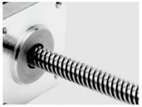
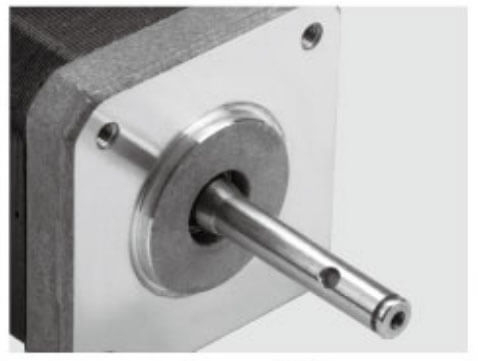
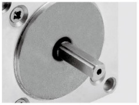
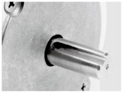
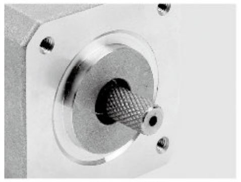
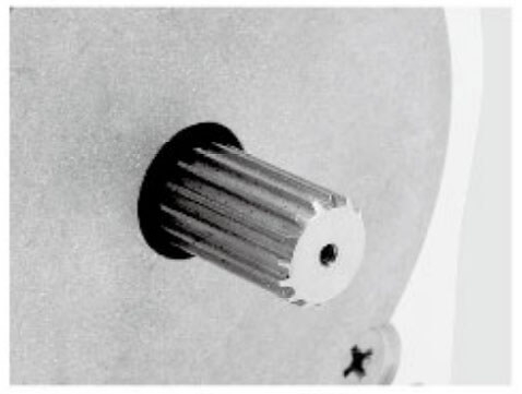
Jkongmotor offer many different shaft options for your motor as well as customizable shaft lengths to make the motor fit your application seamlessly.
Permanent Magnet (PM) Stepper Motors
Permanent magnet stepper motors use a magnetized rotor and a stator with energized windings. They are characterized by simple construction, low manufacturing cost, and moderate positioning accuracy.
Key technical characteristics:
Larger step angles (typically 7.5° to 15°)
Lower resolution compared to other stepper types
Moderate holding torque
Simple drive electronics
Compact mechanical design
Application relevance to inspection equipment:
PM stepper motors are suitable for auxiliary inspection subsystems where ultra-fine positioning is not critical. Examples include:
Sample loading mechanisms
Cover positioning modules
Coarse adjustment fixtures
Sorting and diverter assemblies
They perform reliably in low-cost or secondary motion axes, but their limited resolution and torque linearity restrict their use in high-precision optical or metrology inspection systems.
We apply permanent magnet steppers when space efficiency and cost control outweigh the need for sub-micron positioning performance.
Variable Reluctance (VR) Stepper Motors
Variable reluctance stepper motors operate without permanent magnets. The rotor consists of soft iron laminations that move to positions of minimum magnetic reluctance as stator phases are energized.
Key technical characteristics:
Very small step angles (often 1° or less)
Extremely fast step response
Low rotor inertia
Minimal detent torque
Lower torque output compared to hybrid motors
Application relevance to inspection equipment:
VR stepper motors are well-suited for light-load, high-speed inspection mechanisms, such as:
High-speed scanning mirrors
Rapid probe positioning modules
Lightweight camera alignment stages
Micro-measurement actuators
Their low inertia and high stepping rates make them ideal where speed consistency and micro-position repeatability are required without heavy mechanical loads.
However, VR motors exhibit lower holding torque and greater sensitivity to load variation, which limits their role in vertical axes, multi-stage gantries, or vibration-sensitive optical platforms.
We deploy variable reluctance motors when dynamic responsiveness is the primary performance driver and system loads remain tightly controlled.
Hybrid stepper motors combine permanent magnet and variable reluctance technologies, delivering the most versatile and widely adopted solution for inspection equipment.
Key technical characteristics:
Standard step angles of 1.8° (200 steps/rev) or 0.9° (400 steps/rev)
High torque density
Excellent low-speed smoothness
Strong holding torque
Superior microstepping linearity
Broad driver compatibility
Application relevance to inspection equipment:
Hybrid stepper motors are the dominant choice for professional inspection systems, including:
Automated optical inspection (AOI) platforms
Coordinate measuring machines (CMM)
Semiconductor wafer inspection tools
X-Y vision stages
Non-destructive testing scanners
Precision alignment mechanisms
They provide the optimal balance between:
When combined with high-resolution microstepping drivers, hybrid steppers deliver exceptionally smooth motion, significantly reducing resonance, micro-vibration, and image blur in optical inspection systems.
We select hybrid stepper motors whenever inspection results depend on consistent micron-level motion, stable dwell positioning, and repeatable trajectory execution.
For advanced inspection platforms, we often move beyond open-loop configurations to closed-loop hybrid stepper motors equipped with integrated encoders.
These systems deliver:
Real-time position verification
Automatic step-loss correction
Improved low-speed torque stability
Reduced heat generation
Servo-class performance without tuning complexity
Closed-loop hybrid steppers are particularly valuable in:
High-throughput inspection cells
Vertical measurement axes
Heavy vision gantries
Long-stroke precision scanners
They combine the structural rigidity of stepper motors with the dynamic confidence of servo systems, making them ideal for mission-critical inspection equipment.
Strategic Selection Summary
When selecting the optimal stepper motor type for inspection equipment, we align architecture to application:
Permanent magnet steppers for auxiliary, low-precision, cost-sensitive subsystems
Variable reluctance steppers for ultra-light, high-speed, micro-positioning modules
Hybrid stepper motors for core inspection motion axes demanding accuracy, smoothness, and torque stability
Closed-loop hybrid systems for high-value inspection platforms requiring fault tolerance and performance assurance
This architectural selection ensures that every inspection system achieves mechanical stability, motion repeatability, and long-term operational precision—the essential foundations of reliable inspection performance.
Torque sizing in inspection equipment goes far beyond simple load weight.
We calculate:
Static holding torque to maintain exact positioning during image capture
Dynamic torque across the entire speed profile
Peak acceleration torque for rapid scanning cycles
Disturbance torque margin for cable drag, bearings, and vibration damping
We always include a 30–50% torque safety factor to maintain stability under thermal changes, wear, and system aging.
Key torque considerations include:
An undersized motor introduces micro-oscillation, step loss, and positional drift, all of which directly degrade inspection results.
Step Angle, Resolution & Microstepping for OEM/ODM Customized Hybrid Steppers
Resolution defines inspection precision.
Most inspection platforms rely on 1.8° (200 steps/rev) or 0.9° (400 steps/rev) hybrid motors. We further refine motion using microstepping drivers, enabling:
Higher effective resolution
Smoother motion trajectories
Reduced mechanical resonance
Lower vibration in optical systems
We match step angle to mechanical transmission:
Direct drive stages benefit from 0.9° motors
Lead screw systems optimize around 1.8° motors with 16–64 microsteps
Belt-driven gantries often combine 1.8° motors with high microstep ratios
The objective is always mechanical smoothness, not theoretical resolution numbers.
In inspection equipment, motion quality is inseparable from speed-torque behavior. We do not evaluate a stepper motor by its holding torque alone; we analyze its entire torque curve across operating speeds and how that curve aligns with the real motion profile of the inspection system. Proper matching ensures no missed steps, no micro-stalling, stable scanning motion, and consistent inspection accuracy.
Understanding the Speed-Torque Curve
Every stepper motor exhibits a characteristic speed-torque curve defining how much usable torque remains as rotational speed increases.
Key regions include:
Holding torque region (0 RPM) – Maximum static torque used to maintain precise positioning during image capture or probing
Pull-in region – Speed range where the motor can start, stop, and reverse instantly without ramping
Pull-out region – Maximum torque available while the motor is already running
High-speed decay zone – Region where torque drops rapidly due to inductance and back-EMF
Inspection systems frequently operate in the low-to-mid speed bands, where torque linearity and smoothness are more critical than raw top speed.
We select motors whose curves provide ample torque reserve throughout the entire working velocity range, not just at standstill.
Torque Stability at Low Speed
Most inspection tasks occur at very low speeds or during dwell periods. Examples include:
Optical scanning
Edge detection sweeps
Laser measurement passes
Micro-alignment routines
At low speeds, unstable torque manifests as:
We prioritize motors with:
High detent torque uniformity
Low cogging behavior
Excellent microstepping linearity
High phase inductance consistency
Combined with high-quality drivers, these motors deliver continuous torque output even at fractions of one RPM, ensuring motion smoothness that protects optical clarity and sensor fidelity.
Dynamic Torque and Acceleration Requirements
Inspection equipment rarely moves at constant velocity. Instead, it cycles through:
We calculate dynamic torque based on:
Total moving mass
Lead screw or belt inertia
Coupling compliance
Friction and preload forces
Required acceleration rate
Peak torque demand typically occurs during acceleration and deceleration phases, not steady motion. If the motor cannot supply sufficient dynamic torque, the system experiences:
Step loss
Positional drift
Mechanical ringing
Inconsistent cycle times
We always select motors whose speed-torque curves support acceleration margins of at least 30–50% above calculated system demand.
High-Speed Performance in Inspection Systems
Although inspection emphasizes precision, high-speed movement is critical for productivity. Motors must support:
Stepper motors lose torque at higher speeds due to winding inductance and rising back-EMF. To preserve usable torque, we pair motors with:
This combination flattens the speed-torque curve, allowing the system to achieve higher traverse speeds without torque collapse, maintaining both throughput and reliability.
Matching Motor Curves to Motion Profiles
Inspection motion is defined by profiles, not constant speeds. Typical profiles include:
S-curve acceleration for optical scanning
Trapezoidal profiles for transport axes
Creep-scan profiles for metrology passes
Index-dwell-index cycles for sampling systems
We select motors whose torque curves align with:
The objective is to operate the motor well within its stable torque envelope, never near pull-out limits. This ensures long-term repeatability and zero step loss, even under thermal drift or mechanical aging.
Resonance Control and Curve Smoothness
Stepper motors naturally exhibit mid-band resonance, where torque irregularities can destabilize motion. In inspection equipment, resonance introduces:
We mitigate these effects by:
Selecting motors with smooth torque curves
Using high-resolution microstepping drivers
Implementing electronic damping and current shaping
Operating outside known resonance bands
Closed-loop stepper systems further enhance curve stability by actively correcting micro-position error, flattening the effective torque response across the speed range.
Thermal Influence on Speed-Torque Performance
Torque capability varies with temperature. As winding resistance rises, available current and torque fall. In continuous inspection systems, thermal behavior directly affects:
We select motors whose curves remain thermally stable, supported by:
Efficient magnetic circuits
Optimized copper fill
Insulation rated for elevated temperatures
System-level heat dissipation strategies
This ensures the motor delivers predictable torque output throughout multi-shift operation.
Closed-Loop Systems and Adaptive Torque Control
Closed-loop stepper motors redefine traditional speed-torque limitations. Encoder feedback enables:
Real-time torque optimization
Automatic stall correction
Higher usable speed ranges
Improved low-speed stability
Reduced heating under partial load
For demanding inspection platforms, closed-loop systems significantly expand the effective torque curve, supporting more aggressive motion profiles without sacrificing accuracy.
Strategic Engineering Perspective
We treat speed-torque analysis as a primary design discipline, not a datasheet check. By modeling real load conditions, acceleration needs, and inspection motion profiles, we ensure the selected stepper motor operates in a region that delivers:
Stable torque at scanning speeds
High dynamic margin during repositioning
Zero step loss across duty cycles
Consistent motion quality over system lifetime
When speed-torque characteristics are correctly matched to motion profiles, inspection equipment achieves both precision and productivity, establishing a foundation for reliable, repeatable, and high-confidence inspection results.
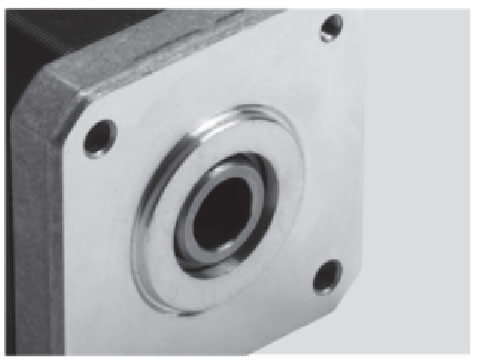
Mechanical Integration and Structural Stability
Stepper motors become mechanical components of the inspection structure.
We evaluate:
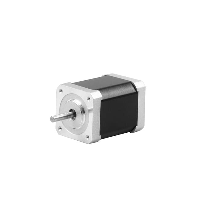
Frame size compatibility (NEMA 8–34)
Shaft diameter and concentricity
Bearing preload and axial play
Mounting flange rigidity
Rotor balance and runout
Inspection equipment amplifies even microscopic mechanical defects. Motors with high-grade bearings, tight machining tolerances, and low detent torque variation provide superior long-term accuracy.
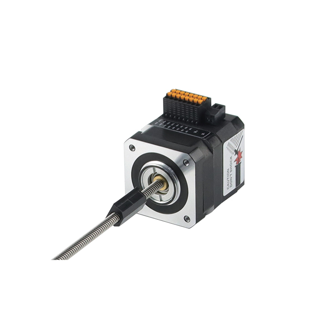
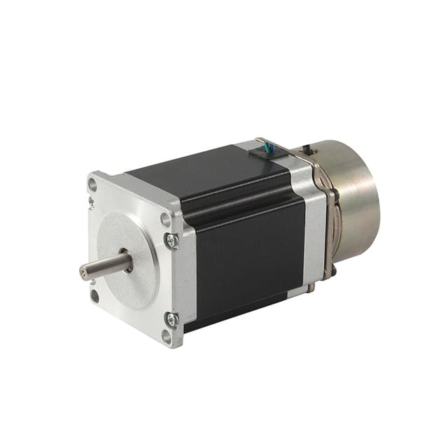
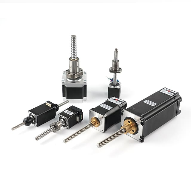
We frequently specify:
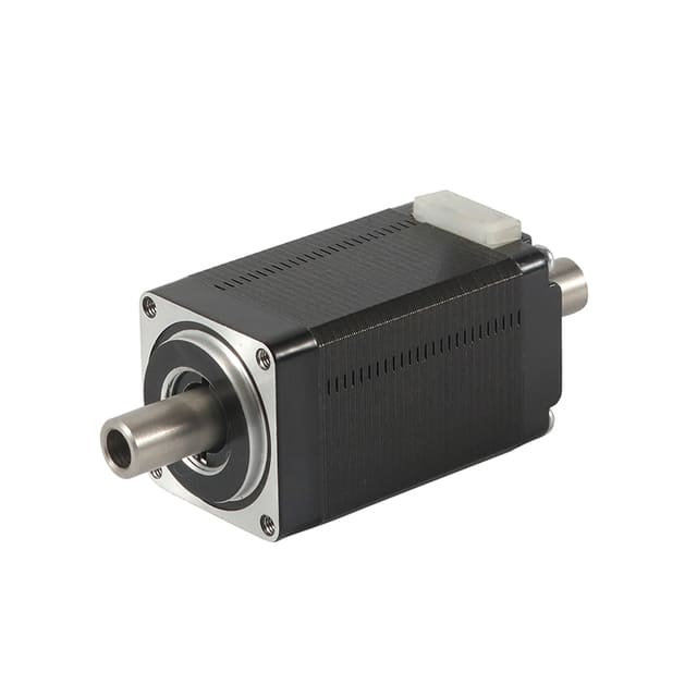
Dual-shaft motors for encoder integration
Flat motors for space-constrained optical heads
Integrated lead screw motors for vertical inspection axes
Thermal Behavior and Long-Term Stability
In inspection equipment, thermal behavior is not a secondary consideration—it is a defining factor in motion accuracy, repeatability, and service life. Even minor temperature fluctuations within a stepper motor can lead to mechanical expansion, magnetic drift, electrical parameter changes, and lubrication degradation, all of which directly influence inspection results. We therefore evaluate every stepper motor not only for performance at room temperature, but for its ability to remain dimensionally, electrically, and magnetically stable over extended operating periods.
Heat Generation Mechanisms in Stepper Motors
Stepper motors generate heat primarily through:
Copper losses (I⊃2;R losses) in the windings
Iron losses in the stator and rotor
Eddy current and hysteresis losses at higher speeds
Driver switching losses transferred into the motor
Because stepper motors draw near-constant current even at standstill, inspection systems that hold position for long dwell times experience continuous thermal loading. Without proper motor selection, this heat buildup causes progressive performance degradation.
Impact of Temperature on Inspection Accuracy
Temperature rise affects inspection equipment in multiple interconnected ways:
Torque reduction: Increasing winding resistance lowers phase current, reducing both holding and dynamic torque.
Dimensional drift: Thermal expansion of the motor frame and shaft alters alignment, stage flatness, and optical focus.
Bearing behavior changes: Lubricant viscosity shifts, affecting preload, friction, and micro-vibration levels.
Magnetic field variation: Permanent magnet strength and flux distribution change slightly with temperature.
Encoder stability risks: In closed-loop systems, thermal gradients can introduce offset drift and signal noise.
In high-precision inspection platforms, these small changes accumulate into measurable positioning error, repeatability loss, and image instability.
Thermal Ratings and Insulation Classes
We analyze thermal specifications beyond nominal current values. Critical parameters include:
Winding insulation class (B, F, H)
Maximum allowable winding temperature
Temperature rise at rated current
Thermal resistance of motor housing
Derating curves versus ambient temperature
Inspection systems typically benefit from motors built with Class F or Class H insulation, enabling stable operation at elevated temperatures while preserving long-term winding integrity.
A higher insulation class does not imply running hotter—it provides thermal headroom, ensuring reliability and consistent performance even under continuous duty cycles.
Thermal Stability and Motion Consistency
True thermal suitability is defined not by maximum temperature, but by how slowly and predictably the motor’s temperature changes.
We prioritize motors with:
High thermal mass for gradual heat rise
Efficient heat conduction from windings to frame
Uniform stator impregnation to prevent hot spots
Low-loss magnetic materials
Stable thermal behavior produces:
This consistency is essential for inspection equipment that must deliver identical results across hours, shifts, and environmental changes.
Managing Continuous Holding Conditions
Inspection equipment frequently holds static positions during:
Image acquisition
Laser scanning
Probe measurement
Calibration routines
During these phases, the stepper motor draws current without producing motion, generating continuous copper loss heat.
To control temperature under these conditions, we integrate:
Current reduction or idle-hold modes in drivers
Closed-loop current optimization
Thermal monitoring within the control system
Frame-level heat dissipation paths
Motors designed with low phase resistance and efficient lamination stacks maintain holding torque with lower thermal load, directly improving long-term stability.
Thermal Influence on Bearing Life and Mechanics
Bearings define the mechanical lifespan of a stepper motor. Elevated temperatures accelerate:
Lubricant oxidation
Grease migration
Seal degradation
Material fatigue
In inspection equipment, bearing degradation manifests as:
Increased runout
Micro-vibration
Acoustic noise
Positional inconsistency
We therefore select motors featuring:
High-temperature bearing grease
Preload optimized for thermal expansion
Low-friction, precision-grade bearings
Documented bearing life ratings under continuous duty
Stable bearing performance ensures repeatable motion characteristics throughout the equipment’s operational lifetime.
Long-Term Electrical Stability
Electrical aging directly affects torque curves and responsiveness. Over time, thermal cycling influences:
Insulation elasticity
Coil resistance drift
Lead wire embrittlement
Connector reliability
Motors designed for inspection platforms use:
Vacuum-pressure impregnation (VPI)
High-purity copper windings
Thermally stable encapsulation resins
Strain-relieved lead terminations
These features preserve electrical symmetry between phases, maintaining smooth torque delivery and microstepping accuracy across years of service.
Closed-Loop Thermal Advantages
Closed-loop stepper motors significantly enhance thermal behavior by:
Reducing unnecessary holding current
Dynamically adjusting torque output
Detecting load changes in real time
Preventing prolonged stall conditions
This adaptive control lowers average motor temperature, producing:
For high-duty inspection equipment, closed-loop architectures deliver measurably superior long-term stability.
Environmental and System-Level Thermal Management
Motor-level design must integrate with system-level thermal engineering. We coordinate:
Motor mounting as a heat sink interface
Chassis airflow pathways
Isolation from heat-generating electronics
Thermal symmetry across multi-axis platforms
Inspection equipment designed with unified thermal management ensures that motor behavior remains predictable, protecting both mechanical accuracy and electronic calibration.
Engineering for Multi-Year Stability
Long-term inspection reliability depends on selecting motors engineered for:
Continuous operation at partial load
Minimal thermal cycling amplitude
Stable magnetic and electrical properties
Documented endurance testing
We treat stepper motors as precision thermal components, not merely torque devices. When thermal behavior is controlled and long-term stability is engineered from the outset, inspection systems achieve sustained accuracy, reduced maintenance, and consistent measurement integrity over their full service lifecycle.
Thermal mastery is foundational to inspection performance. A stepper motor that remains cool, stable, and predictable becomes a silent guarantor of measurement reliability and system credibility.
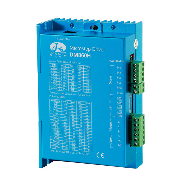
Electrical Parameters and Driver Compatibility
Stepper motors perform only as well as their drivers.
We align:
Rated current
Phase resistance
Inductance
Voltage ceiling
Wiring configuration
Inspection equipment typically benefits from:
Low inductance motors for smooth low-speed control
High-voltage drivers for extended torque bandwidth
Digital current regulation for reduced acoustic noise
We also ensure compatibility with:
Motion controllers
Vision synchronization triggers
PLC-based inspection workflows
EtherCAT or CANopen networks
Electrical integration quality determines system responsiveness and long-term reliability.
Environmental and Contamination Considerations
Inspection systems frequently operate in controlled environments that demand specialized motor construction.
We evaluate:
For semiconductor, medical, and optical inspection, we often specify:
Environmental compatibility protects both inspection results and sensitive instrumentation.
Reliability, Duty Cycle, and Lifecycle Engineering
Inspection equipment typically runs continuous production cycles. Motor selection therefore includes lifecycle engineering.
We verify:
We prefer manufacturers offering:
Traceable quality systems
Long-term production stability
Customization capability
Technical documentation depth
A properly selected stepper motor becomes a maintenance-neutral component across the equipment’s operational lifespan.
System-Level Optimization Strategy
Selecting a stepper motor for inspection equipment achieves true performance only when it is embedded within a system-level optimization framework. We do not treat the motor as an isolated actuator; we engineer the entire motion ecosystem—motor, driver, mechanics, sensors, structure, and thermal management—as a unified precision instrument. System-level optimization ensures that inspection equipment delivers repeatable accuracy, smooth motion, high throughput, and long-term stability.
Motor, Driver, and Controller Synergy
The motor’s intrinsic characteristics define potential performance, but the driver and motion controller determine how much of that potential becomes usable.
We optimize this triad by aligning:
Motor inductance with driver voltage capability
Rated current with digital current regulation
Step angle with controller interpolation resolution
Torque curve with commanded acceleration limits
Advanced inspection platforms employ high-resolution microstepping drivers and precision motion controllers capable of:
Sub-step interpolation
Jerk-limited trajectory planning
Real-time feedback processing
Synchronization with vision and sensing subsystems
This integration transforms discrete stepping into continuous, vibration-minimized motion, essential for optical clarity and measurement repeatability.
Mechanical Transmission and Structural Integration
Mechanical design is the dominant factor in motion quality. We optimize mechanical integration to preserve motor precision and suppress disturbances.
Key focus areas include:
Transmission efficiency and backlash elimination
Inertia matching between motor and load
Coupling stiffness and torsional compliance
Stage rigidity and modal behavior
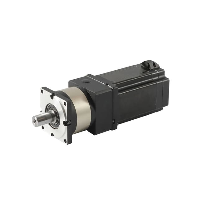
We align stepper motors with:
Preloaded ball screws for metrology axes
Anti-backlash lead screws for compact inspection modules
Precision belt systems for long-travel vision gantries
Direct-drive rotary stages for angular inspection platforms
Structural resonance analysis guides mounting design, ensuring the motor operates outside dominant vibrational modes, preserving smooth scanning and stable dwell positioning.
Vibration Management and Motion Smoothness
Inspection equipment magnifies even microscopic vibration. System-level optimization therefore emphasizes vibration suppression across all components.
We integrate:
High microstep ratios with sinusoidal current shaping
Electronic damping and mid-band resonance control
Low-runout shafts and precision bearings
Stiff, symmetrical mounting interfaces
Where required, we deploy:
The result is a motion platform that supports blur-free imaging, noise-free probing, and stable sensor acquisition.
Thermal Architecture Integration
Thermal engineering is central to system optimization.
We design the motor into the equipment’s thermal architecture, not as a heat source to manage later.
This includes:
Direct conductive paths from motor frame to chassis
Balanced thermal distribution across multi-axis stages
Isolation from heat-sensitive optical assemblies
Predictable airflow patterns or passive dissipation zones
Driver current strategies, idle reduction modes, and closed-loop torque optimization are coordinated to minimize temperature gradients that could compromise alignment and calibration.
Closed-Loop Feedback and Error Management
System-level optimization increasingly incorporates feedback-driven architectures.
We integrate encoders not merely for stall protection, but for:
Micro-position correction
Load disturbance compensation
Thermal drift mitigation
Repeatability enhancement
By unifying motor feedback with:
Vision system references
Force or probe sensors
Environmental monitors
we establish a multi-layer control ecosystem that actively maintains inspection precision under changing loads and operating conditions.
Motion Profiles Aligned with Inspection Tasks
We tailor motion not to theoretical performance limits, but to inspection task requirements.
Motion profiles are engineered to support:
Ultra-smooth low-speed scanning
Rapid, non-resonant repositioning
High-stability dwell intervals
Synchronized multi-axis trajectories
We implement:
This alignment ensures that the motor operates within its most linear, thermally stable, and vibration-minimized region, extending both accuracy and lifespan.
Electrical Infrastructure and Signal Integrity
Electrical design directly affects mechanical performance.
We optimize:
Power supply stability and current headroom
Cable routing to minimize drag and inductive interference
Shielding to protect encoder and sensor signals
Grounding architecture to prevent noise coupling
In inspection equipment, poor electrical design manifests mechanically as:
Micro-oscillation
Torque ripple
Encoder miscounts
Inconsistent homing
System-level electrical optimization preserves the motor’s theoretical precision in real-world operation.
Lifecycle Engineering and Maintainability
We design inspection motion platforms for multi-year stability, not initial performance only.
System-level planning incorporates:
We also prioritize:
Component traceability
Long-term supply continuity
Field-replaceable motor modules
Accessible thermal and electrical diagnostics
This lifecycle perspective transforms the stepper motor from a replaceable part into a reliable precision subsystem.
Unified Performance Outcome
When system-level optimization is correctly executed, the stepper motor becomes:
A stable torque source
A precision positioning element
A thermally predictable structure
A feedback-enabled control participant
This unified design approach produces inspection equipment that delivers:
Repeatable sub-millimeter and micron-level motion
High-speed productivity without step loss
Long-term calibration retention
Low maintenance and high operational confidence
System-level optimization ensures that every characteristic of the stepper motor is preserved, amplified, and protected within the inspection platform. Only through this integrated engineering strategy can inspection equipment consistently achieve precision, reliability, and longevity at industrial scale.
Conclusion: Engineering Precision into Inspection Motion
Choosing a stepper motor for inspection equipment requires rigorous evaluation of torque behavior, resolution strategy, mechanical integrity, thermal stability, and control architecture. By aligning motor selection with the unique demands of inspection platforms, we ensure:
Precision inspection begins with precision motion—and precision motion begins with the correct stepper motor.
1. What makes inspection equipment motion different from general automation?
Inspection systems demand micron-level positioning, high low-speed stability, and minimal vibration to ensure measurement accuracy.
2. Why are hybrid stepper motors widely used in inspection equipment?
Hybrid steppers combine high resolution, strong torque, smooth low-speed behavior, and compatibility with microstepping drivers, making them ideal for inspection motion axes.
3. What is an OEM/ODM customized hybrid stepper motor?
It is a motor tailored through OEM/ODM services to meet specific inspection application requirements (torque, size, integration, IP rating, etc.).
4. How do I decide between permanent magnet, variable reluctance, and hybrid stepper motors for inspection?
Choose based on precision needs: permanent magnet for auxiliary axes, variable reluctance for light high-speed axes, and hybrid for core precision motion.
5. What role does torque specification play in inspection motion control?
Accurate torque sizing ensures the motor can handle static holding, dynamic acceleration, and disturbance loads without losing steps.
6. What is microstepping, and why is it important here?
Microstepping divides full steps into smaller increments, smoothing motion and increasing effective resolution—critical for optical and precision inspection.
7. How does step angle affect inspection accuracy?
Smaller step angles (e.g., 0.9° instead of 1.8°) provide finer resolution, contributing to more precise positioning.
8. Do inspection systems require closed-loop control?
For high-value, mission-critical inspection, closed-loop hybrid steppers with encoders offer position feedback and correction, improving reliability.
9. What is the significance of the speed–torque curve for hybrid steppers?
Matching the whole speed–torque profile (not just holding torque) to motion requirements avoids step loss and ensures smooth motion across speeds.
10. Why is thermal performance important in inspection equipment?
Heat alters resistance and torque capability; motors with good thermal management provide stable torque over long inspection cycles.
11. How do OEM/ODM services improve stepper motor selection?
Customization allows adjustment of motor parameters, housings, connectors, protection levels, and mechanical fit specific to the inspection machine design.
12. What environmental factors must be considered when choosing a motor?
Temperature, humidity, dust, vibration, and electromagnetic noise influence protection levels and construction choices.
13. Can a customized hybrid stepper motor include integrated feedback?
Yes—OEM/ODM designs can incorporate encoders or sensors to enable closed-loop control.
14. How does vibration affect inspection performance?
Vibration introduces measurement noise or image blur; smooth motion from hybrid motors and microstepping reduces such issues.
15. What duty cycle considerations are relevant for inspection steppers?
High repeatability and uptime require motors capable of continuous operation with stable torque and heat dissipation.
16. Is driver matching important for optimized performance?
Yes—drivers must support required microstepping modes and current to maintain smooth, controlled motion.
17. How do I ensure long-term positional repeatability?
Select motors with consistent torque, optimized magnetic design, and high-quality manufacturing tolerances.
18. Why might closed-loop hybrid steppers be preferred over open-loop?
Closed-loop systems detect step loss and correct motion, improving precision and reducing system tuning.
19. What mechanical integrations are critical for inspection motors?
Proper couplings, minimal backlash transmissions, and rigid mounts contribute to accurate motion transfer.
20. How can I balance cost and performance when choosing stepper motors?
OEM/ODM customization lets you tailor specs to what the application truly needs—avoiding overspecification and unnecessary cost while maintaining required precision.