DC Motor Types: A Comprehensive Technical Overview
DC motors are widely used across industrial automation, robotics, electric vehicles, and consumer equipment due to their simple control, high starting torque, and predictable performance. Based on how the magnetic field is generated and how the field winding is connected to the armature, DC motors are classified into several distinct types. Each type offers unique electrical and mechanical characteristics suited to specific applications.
Below is a clear, structured, and technically accurate overview of all major DC motor types.
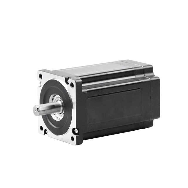
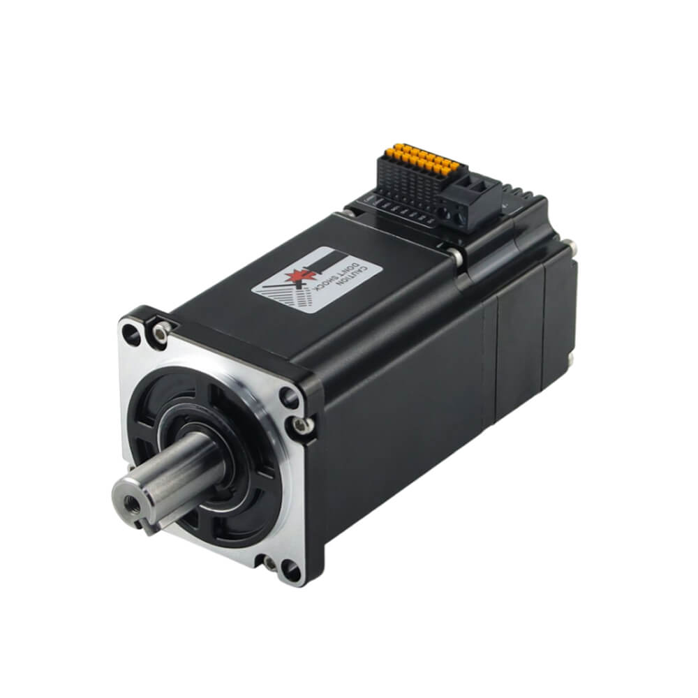
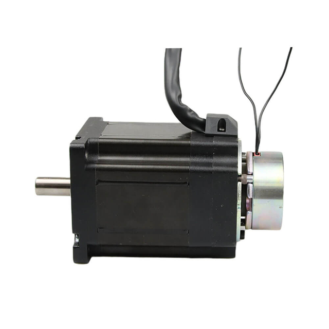
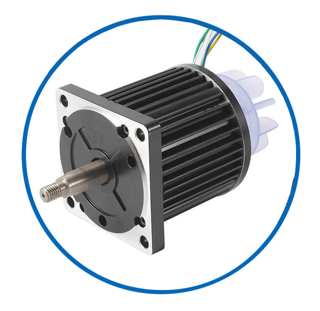
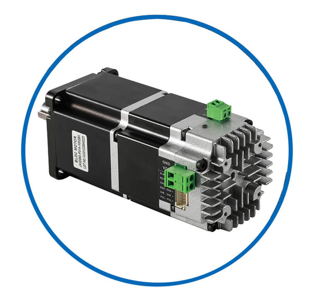
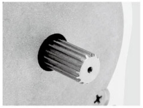
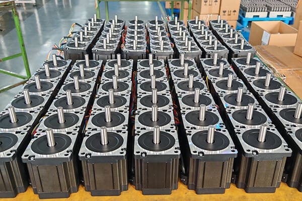
Bldc Motor Customized Service
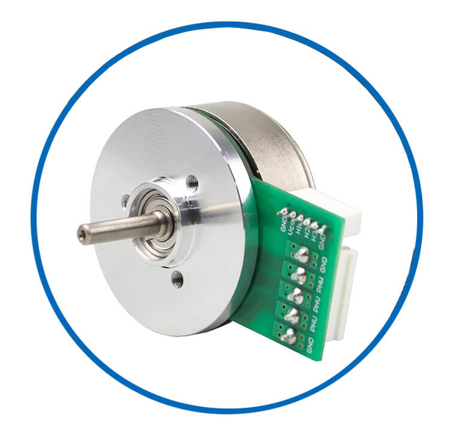
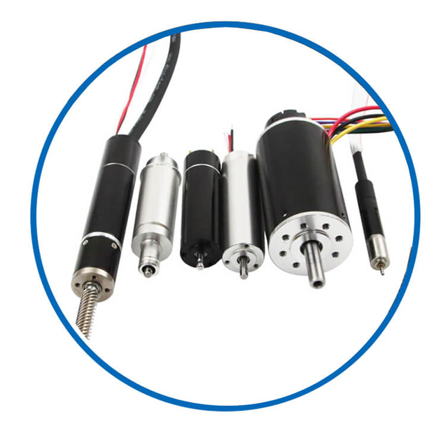
As a professional brushless dc motor manufacturer with 13 years in china, Jkongmotor offer various bldc motors with customized requirements, including 33 42 57 60 80 86 110 130mm, additionally, gearboxes, brakes, encoders, brushless motor drivers and integrated drivers are optional.
![bldc motor supplier]() | ![bldc motor supplier]() | ![bldc motor supplier]() | ![bldc motor supplier]() | ![bldc motor supplier]() | Professional custom brushless motor services safeguard your projects or equipment. No Brushes – Reduced Maintenance and Increased Lifespan High Efficiency and Low Power Loss High Torque-to-Weight Ratio Precise Speed and Position Control Quiet and Smooth Operation Wide Speed Range and Dynamic Performance Excellent Thermal Management Customizable Designs and Modular Configurations Multiple Control Methods Integration with Digital Interfaces and Sensors |
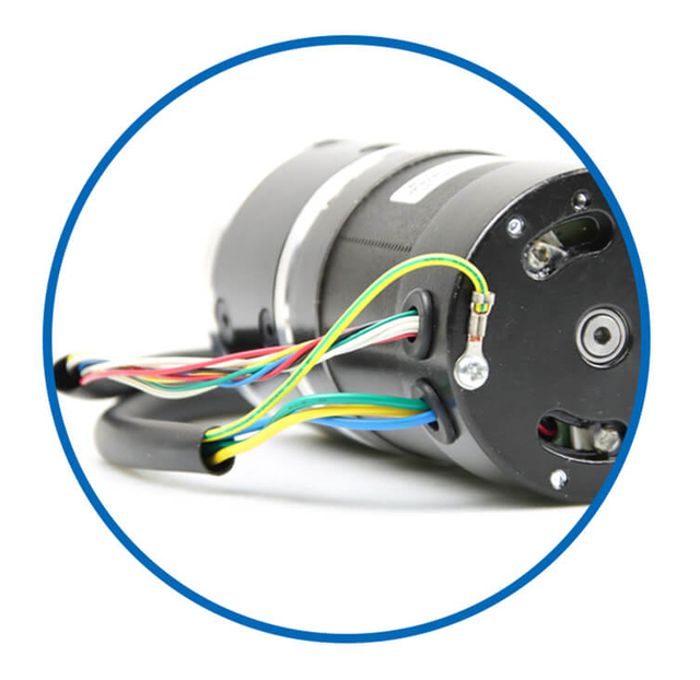
| Wires | Covers | Fans | Shafts | Integrated Drivers |
![bldc motor supplier]() | ![bldc motor supplier]() | ![bldc motor supplier]() | ![bldc motor supplier]() | ![bldc motor supplier]() |
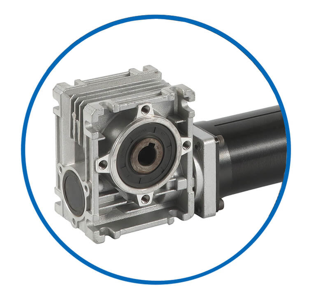
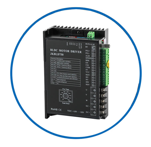
| Brakes | Gearboxes | Out Rotors | Coreless Dc | Drivers |
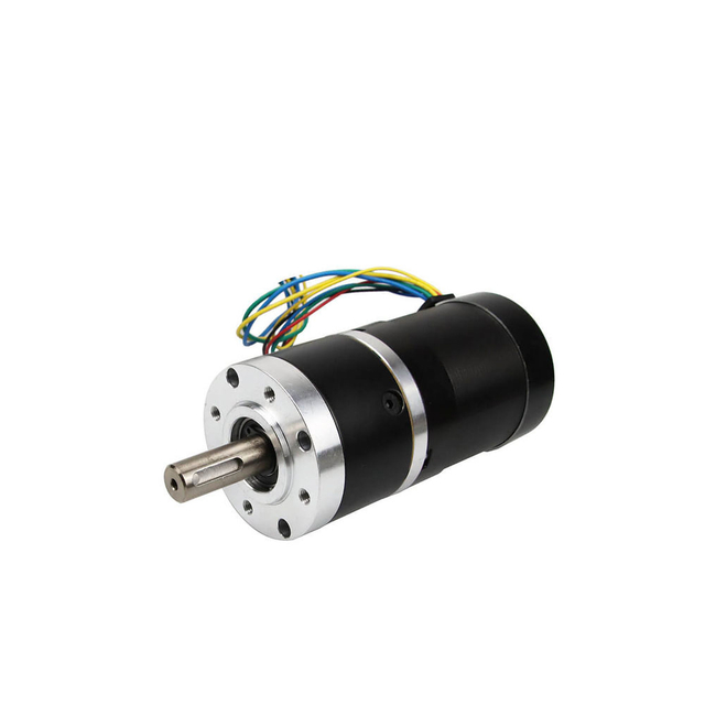
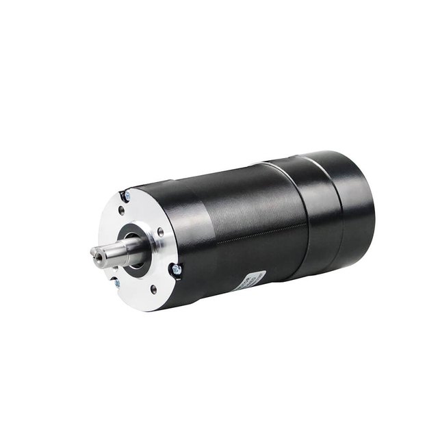
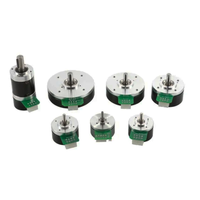
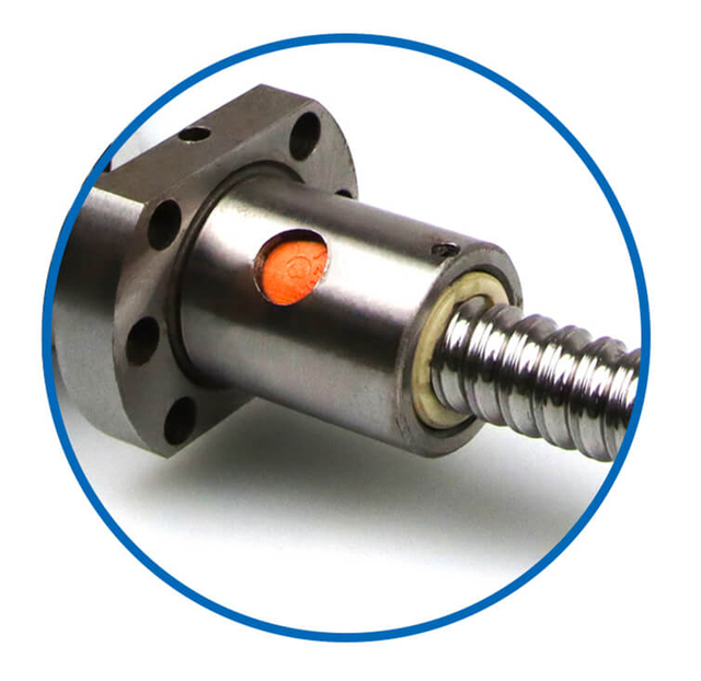
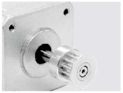
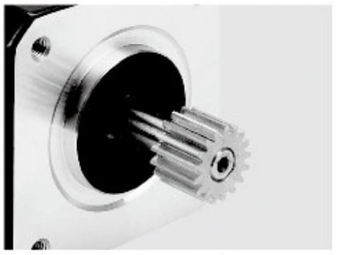
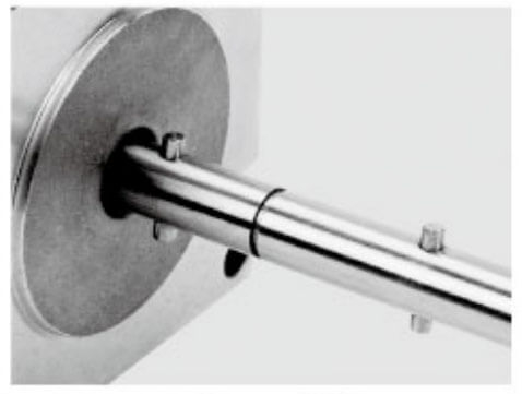
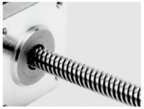
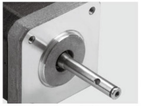
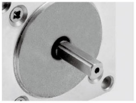
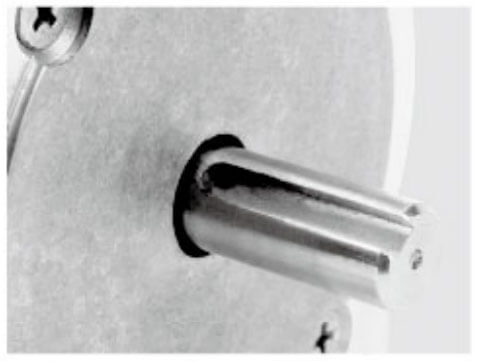
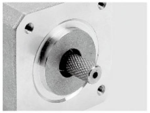
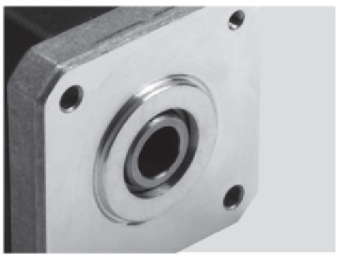
Motor Shaft Customized Service
Jkongmotor offer many different shaft options for your motor as well as customizable shaft lengths to make the motor fit your application seamlessly.
Brushed DC motors use carbon brushes and a mechanical commutator to transfer electrical power to the rotating armature. They are valued for their simplicity and low initial cost.
1.1 Series DC Motor
In a series DC motor, the field winding is connected in series with the armature.
Key characteristics:
Very high starting torque
Torque proportional to the square of armature current
Speed varies significantly with load
Dangerous no-load speed condition
Typical applications:
Electric traction
Cranes and hoists
Elevators
Starter motors
1.2 Shunt DC Motor
In a shunt DC motor, the field winding is connected in parallel with the armature.
Key characteristics:
Typical applications:
1.3 Compound DC Motor
A compound DC motor combines both series and shunt field windings.
Types of compound motors:
Key characteristics:
Typical applications:
Rolling mills
Presses
Heavy-duty conveyors
Elevators
2. Separately Excited DC Motor
In a separately excited DC motor, the field winding is powered from an independent external DC source.
Key characteristics:
Typical applications:
3. Permanent Magnet DC Motor (PMDC)
A permanent magnet DC motor uses permanent magnets instead of field windings to generate magnetic flux.
Key characteristics:
Limitations:
Typical applications:
A brushless DC motor eliminates mechanical commutation and uses electronic commutation controlled by a drive or controller.
Key characteristics:
Commutation methods:
Typical applications:
Electric vehicles
Drones
Industrial automation
HVAC systems
CNC machines
5. Coreless DC Motor
A coreless DC motor features a rotor without an iron core, reducing inertia and losses.
Key characteristics:
Typical applications:
Medical instruments
Aerospace systems
Precision robotics
Optical equipment
A DC servo motor is designed for closed-loop control, combining a DC motor with feedback devices such as encoders or tachometers.
Key characteristics:
Precise position, speed, and torque control
Fast dynamic response
High accuracy
Excellent low-speed performance
Typical applications:
7. Universal Motor
A universal motor can operate on both AC and DC power supplies and is technically a series-wound motor.
Key characteristics:
High speed
High starting torque
Compact size
Noisy operation
Shorter lifespan
Typical applications:
Power tools
Vacuum cleaners
Household appliances
Comparison Summary of DC Motor Types
| DC Motor Type | Starting Torque | Speed Regulation | Efficiency | Maintenance |
| Series DC Motor | Very High | Poor | Moderate | High |
| Shunt DC Motor | Moderate | Excellent | Moderate | High |
| Compound DC Motor | High | Good | Moderate | High |
| Separately Excited | Moderate–High | Excellent | High | High |
| PMDC Motor | Moderate | Good | High | Low |
| BLDC Motor | High | Excellent | Very High | Very Low |
| Coreless DC Motor | Moderate | Excellent | Very High | Low |
| DC Servo Motor | High | Excellent | High | Low |
Conclusion
Understanding DC motor types is essential for selecting the right motor for any application. From high-torque series motors to precision-controlled DC servo motors and high-efficiency BLDC motors, each type offers distinct advantages in terms of performance, control, efficiency, and durability. Proper motor selection ensures optimal system reliability, energy efficiency, and long-term operational success.
Understanding the torque equation for a DC motor is fundamental for engineers, designers, OEM manufacturers, and automation professionals who demand precise motor performance, accurate load calculations, and optimal efficiency. In this article, we present a comprehensive, technically rigorous, and application-oriented explanation of the DC motor torque equation, covering electromagnetic principles, mathematical derivations, performance factors, and real-world engineering implications.
We write in a formal we-based technical style, delivering authoritative insights suitable for academic reference, industrial design, and advanced motor selection.
Fundamental Concept of Torque in DC Motors
Torque in a DC motor represents the rotational force produced on the motor shaft as a result of electromagnetic interaction between the armature current and the magnetic field. It is the primary parameter that determines the motor’s ability to start loads, accelerate inertia, and maintain mechanical output under varying conditions.
In DC motors, torque generation is governed by Lorentz force principles, where a current-carrying conductor placed within a magnetic field experiences a force proportional to both the current and the field strength.
The Standard Torque Equation for a DC Motor
The basic torque equation of a DC motor is expressed as:
T = Kₜ × Φ × Iₐ
Where:
T = Electromagnetic torque (Nm)
Kₜ = Motor torque constant
Φ = Magnetic flux per pole (Wb)
Iₐ = Armature current (A)
This equation clearly establishes that torque is directly proportional to armature current and magnetic flux, making current control the most effective method for torque regulation in DC motor systems.
Derivation of the DC Motor Torque Equation
The torque equation originates from the force acting on current-carrying conductors in the armature:
F = B × I × L
Where:
Considering the radius of the armature and the total number of conductors, the resulting rotational torque becomes proportional to:
These physical parameters are consolidated into the motor torque constant (Kₜ), resulting in the simplified and widely used torque equation.
Torque Equation in Terms of Electrical Power
Torque can also be related to electrical power and angular velocity:
T = Pₘ / ω
Where:
By substituting DC motor voltage and current relationships, torque becomes:
T = (E × Iₐ) / ω
This form is particularly valuable in system-level simulations and drive efficiency analysis, where electrical input and mechanical output must be correlated.
Torque Equation Using Back EMF Constant
In practical engineering applications, the torque equation is frequently expressed using the back electromotive force constant:
T = Kₜ × Iₐ
For constant-field DC motors (such as permanent magnet DC motors), magnetic flux remains constant. Therefore:
This linearity makes DC motors highly desirable for servo control, robotics, conveyors, and precision automation systems.
Torque-Speed Relationship in DC Motors
The torque equation is closely linked to the speed equation:
N = (V − IₐRₐ) / (Kₑ × Φ)
Combining torque and speed equations yields the classic linear torque-speed characteristic of DC motors:
This predictable behavior simplifies motion profiling, load matching, and closed-loop control design.
Types of DC Motors and Their Torque Equations
Shunt DC Motor Torque Equation
In shunt motors, magnetic flux remains nearly constant:
T ∝ Iₐ
This results in:
Series DC Motor Torque Equation
In series motors, flux varies with current:
T ∝ Iₐ⊃2;
This produces:
Extremely high starting torque
Nonlinear torque-current behavior
Common use in traction systems and lifting equipment
Compound DC Motor Torque Equation
Compound motors combine both shunt and series characteristics:
Factors Affecting DC Motor Torque
Several critical parameters influence the torque equation:
Armature current magnitude
Magnetic saturation of the field
Armature resistance
Brush contact voltage drop
Temperature rise and copper losses
Understanding these factors is essential for accurate torque prediction under real operating conditions.
Practical Torque Calculation Example
Assume:
Then:
T = 0.8 × 5 = 4 Nm
This straightforward calculation demonstrates why current measurement is the primary feedback signal in DC motor torque control systems.
Torque Control in Modern DC Motor Drives
Modern DC drives implement torque control using:
Closed-loop current regulators
PWM-based armature voltage control
Digital signal processors (DSPs)
By maintaining precise armature current, these systems achieve:
Relationship Between Torque Equation and Motor Efficiency
While the torque equation defines force generation, efficiency depends on:
Copper losses (I⊃2;R)
Iron losses
Mechanical friction
Commutation quality
Optimized torque control minimizes losses while delivering maximum usable shaft output.
Applications Where the DC Motor Torque Equation Is Critical
The DC motor torque equation plays a decisive role in engineering systems where accurate force generation, controlled acceleration, and predictable mechanical output are mandatory. In these applications, torque is not an abstract parameter—it directly determines system safety, efficiency, responsiveness, and operational reliability. Below, we present the key application domains where precise understanding and application of the DC motor torque equation are absolutely critical.
1. Electric Traction Systems
In electric traction, including electric locomotives, trams, and mining vehicles, the torque equation governs:
High torque at low speed is achieved by controlling armature current, as defined by the torque equation. Miscalculation can result in wheel slip, overheating, or insufficient starting force.
2. Cranes, Hoists, and Lifting Equipment
Lifting systems demand precise torque control to safely raise and lower loads.
Critical torque considerations include:
Load weight conversion into required shaft torque
Smooth start and stop under full load
Prevention of mechanical shock
The torque equation ensures that current limits are set correctly to prevent motor stall or structural overload.
3. Industrial Conveyors and Material Handling Systems
Conveyors rely on accurate torque calculations to:
Overcome static friction at startup
Maintain constant speed under variable loads
Prevent belt slippage and gearbox stress
The DC motor torque equation directly determines drive sizing, gear ratio selection, and thermal performance.
4. CNC Machines and Machine Tools
Precision machining requires stable and repeatable torque output to maintain cutting accuracy.
Applications include:
Lathes
Milling machines
Grinding systems
Torque equation analysis ensures constant cutting force, minimized vibration, and improved surface finish.
5. Robotics and Automated Manipulators
Robotic joints depend on accurate torque estimation to:
In robotic arms, the torque equation is used to map electrical current to mechanical joint force, enabling reliable motion planning and collision detection.
6. DC Servo Drive Systems
In servo systems, torque is the primary controlled variable.
The torque equation enables:
Servo drives use real-time current feedback to enforce the torque equation with high precision.
7. Electric Vehicles and Mobile Platforms
In electric vehicles and autonomous mobile robots, torque equations are critical for:
Accurate torque modeling ensures energy efficiency, traction stability, and passenger comfort.
8. Test Benches and Dynamometers
Motor testing equipment relies on precise torque calculations to:
Validate motor performance
Measure efficiency curves
Conduct endurance testing
The torque equation allows direct correlation between electrical input and mechanical output, ensuring measurement accuracy.
9. Medical and Surgical Equipment
Medical devices require smooth, controlled, and predictable torque.
Typical applications include:
Surgical robots
Infusion pumps
Rehabilitation devices
In these systems, torque equation accuracy directly impacts patient safety and procedural precision.
10. Aerospace and Defense Systems
In aerospace actuators and defense mechanisms, torque errors are unacceptable.
Torque equation usage supports:
Flight control surface actuation
Radar positioning systems
Weapon guidance mechanisms
Reliability and repeatability are ensured through strict torque-current modeling.
11. Printing, Packaging, and Textile Machinery
These machines require consistent torque to maintain:
The torque equation helps prevent material stretching, tearing, and misalignment.
12. Renewable Energy and Energy Storage Systems
In wind turbine yaw systems and energy storage actuators, DC motor torque equations are essential for:
Load balancing
Positioning accuracy
System durability
Proper torque control extends component life and improves overall efficiency.
Conclusion
The DC motor torque equation is critical in any application where electrical input must be translated into predictable mechanical output. From heavy industrial machinery to precision medical systems, it enables engineers to design, control, and optimize motion systems with accuracy, safety, and efficiency. Mastery of this equation is fundamental to achieving reliable performance across a wide spectrum of modern electromechanical applications.
Engineering Advantages of DC Motor Torque Linearity
The torque linearity of DC motors—the direct proportional relationship between armature current and output torque—is one of the most valuable characteristics in electrical drive engineering. This inherent linear behavior provides significant design, control, and performance advantages across a wide range of industrial and precision motion applications. Below, we present a detailed engineering analysis of why DC motor torque linearity remains a critical advantage in modern electromechanical systems.
1. Direct and Predictable Torque Control
In DC motors with constant magnetic flux, torque is expressed as:
T ∝ Iₐ
This direct proportionality allows engineers to:
Predict torque output accurately from current values
Implement simple and reliable control algorithms
Achieve fast and stable torque regulation
This predictability significantly reduces system complexity in both open-loop and closed-loop drive systems.
2. High Precision in Low-Speed Operation
At low speeds, many motor types suffer from nonlinearities and torque ripple. DC motors maintain smooth and linear torque output, even near zero speed.
Engineering benefits include:
This makes DC motors ideal for servo drives, robotics, and precision machinery.
3. Simplified Drive Electronics and Control Architecture
Torque linearity allows DC motor drives to:
Use current as the primary control variable
Avoid complex vector transformations
Minimize computational overhead
As a result, control systems can be implemented using simpler hardware and firmware, reducing cost and increasing reliability.
4. Fast Dynamic Response
Because torque responds instantaneously to changes in armature current, DC motors exhibit:
This advantage is critical in applications requiring quick load response and high dynamic accuracy.
5. Accurate Load Estimation and Monitoring
Linear torque-current behavior enables:
By monitoring current, engineers can infer mechanical load changes without additional sensors.
6. Stable Closed-Loop Servo Performance
In closed-loop systems, torque linearity ensures:
High loop gain without instability
Consistent control behavior across operating ranges
Reduced tuning complexity
This results in robust and repeatable servo performance under varying loads and speeds.
7. Reduced Torque Ripple and Mechanical Stress
Linear torque generation minimizes:
This leads to longer mechanical life and quieter operation.
8. Enhanced Energy Efficiency Under Dynamic Loads
Precise torque control allows the motor to:
This improves overall system energy efficiency, especially in variable-load applications.
9. Improved Safety and Overload Protection
Torque linearity simplifies:
Protective functions can be implemented with high accuracy, reducing the risk of mechanical damage.
10. Scalability Across Power Ranges
The linear torque-current relationship remains valid across:
Small precision motors
Medium industrial drives
High-torque DC systems
This scalability allows engineers to apply consistent design principles across multiple product platforms.
11. Ideal Platform for Advanced Motion Control
DC motor torque linearity supports:
These advanced techniques rely on predictable motor behavior, which DC motors naturally provide.
12. Engineering Simplicity and Design Confidence
Ultimately, torque linearity delivers:
Engineers gain greater confidence in performance predictions, improving both development efficiency and product reliability.
Conclusion: Why the DC Motor Torque Equation Matters
The engineering advantages of DC motor torque linearity extend far beyond basic operation. This fundamental characteristic enables precise control, fast response, simplified electronics, and reliable performance, making DC motors an enduring choice in applications where accuracy, predictability, and robustness are essential. Despite advances in alternative motor technologies, torque linearity ensures DC motors remain a cornerstone of high-performance motion systems.
The torque equation for a DC motor is more than a mathematical formula—it is the foundation of motor design, control, and application engineering. By clearly defining the relationship between current, magnetic flux, and mechanical output, it enables precise torque control, predictable performance, and reliable system integration across industries.
Mastery of this equation empowers engineers to design better drives, select optimal motors, and deliver superior motion solutions.