Brushless Dc Motor Introductions:
A brushless DC motor (BLDC) is an electric motor powered by direct current (DC) and operated by an electronic controller, which eliminates the need for mechanical brushes and a commutator. Here is a concise introduction to its key aspects:
A BLDC motor fundamentally consists of a stator (the stationary part with wire windings) and a rotor (the rotating part with permanent magnets).
Principle of Operation:
The electronic controller continuously energizes the stator windings in a specific sequence. This creates a rotating magnetic field that "pulls" the permanent magnet rotor along, causing it to turn. The controller uses sensors (or sensorless techniques) to detect the rotor's position and determine the exact timing for switching the current.
Key Components:
Stator: Typically has three-phase windings.
Rotor: Uses high-strength permanent magnets (e.g., Neodymium).
Electronic Controller (ESC): The "brain" that drives the motor by switching power to the windings.
We stand at the forefront of a motion revolution, driven by the unparalleled efficiency, reliability, and performance of brushless DC (BLDC) motors. The working principle of brushless motors represents a fundamental departure from traditional brushed DC motors, replacing mechanical commutation with intelligent electronic control. This transition from carbon brushes and a physical commutator to a system of permanent magnets, wound stators, and solid-state electronics is not merely an incremental improvement; it is a complete re-engineering of rotational force generation. In this comprehensive analysis, we will dissect the core electromagnetic principles, the critical role of power electronics, and the sophisticated control algorithms that define the operation of these dominant motors in modern engineering.
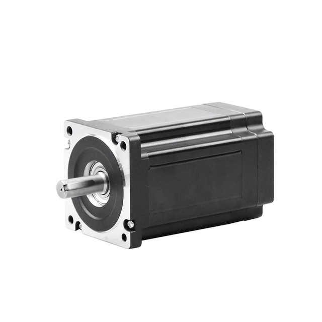
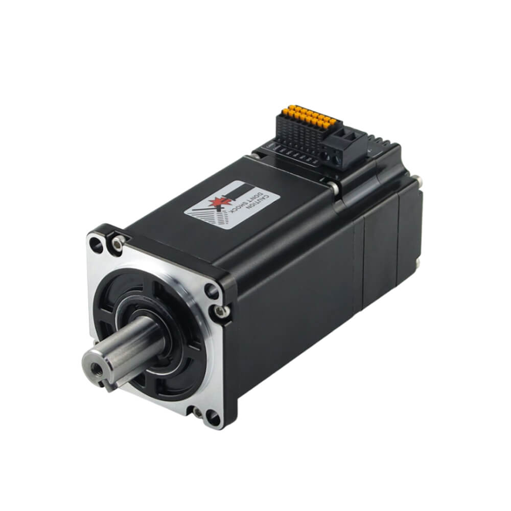
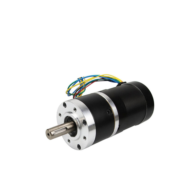
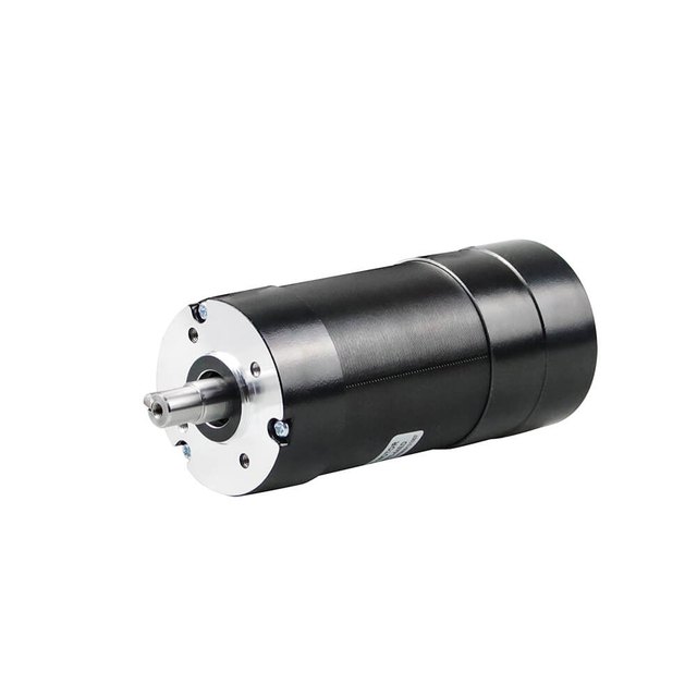
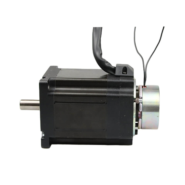
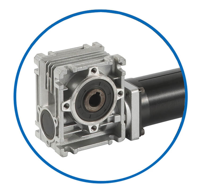
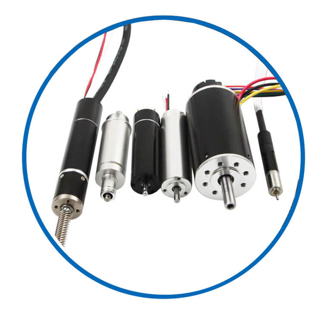
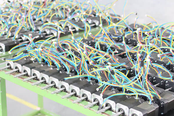
Bldc Motor Customized Service
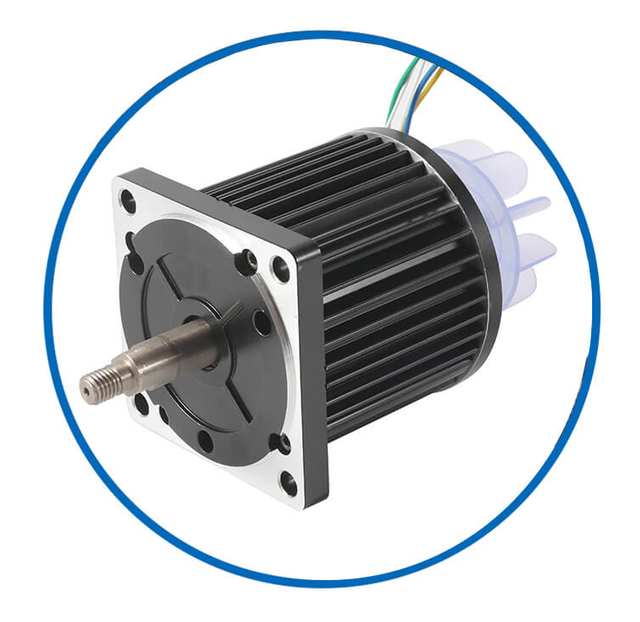
As a professional brushless dc motor manufacturer with 13 years in china, Jkongmotor offer various bldc motors with customized requirements, including 33 42 57 60 80 86 110 130mm, additionally, gearboxes, brakes, encoders, brushless motor drivers and integrated drivers are optional.
![bldc motor supplier]() | ![bldc motor supplier]() | ![bldc motor supplier]() | ![bldc motor supplier]() | ![bldc motor supplier]() | Professional custom brushless motor services safeguard your projects or equipment. No Brushes – Reduced Maintenance and Increased Lifespan High Efficiency and Low Power Loss High Torque-to-Weight Ratio Precise Speed and Position Control Quiet and Smooth Operation Wide Speed Range and Dynamic Performance Excellent Thermal Management Customizable Designs and Modular Configurations Multiple Control Methods Integration with Digital Interfaces and Sensors |
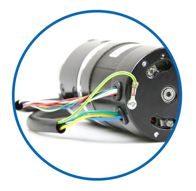
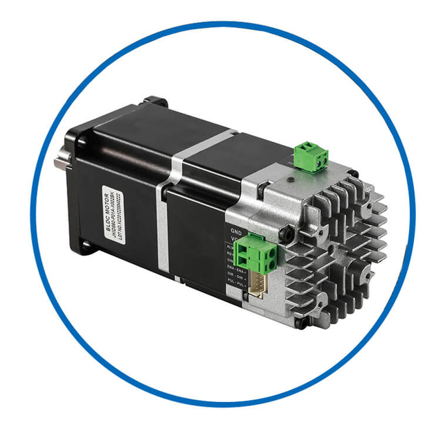
| Wires | Covers | Fans | Shafts | Integrated Drivers |
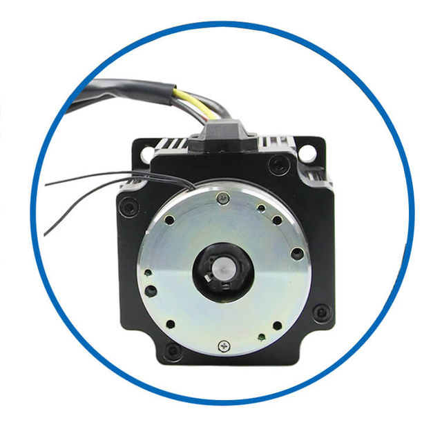
![bldc motor supplier]() | ![bldc motor supplier]() | ![bldc motor supplier]() | ![bldc motor supplier]() | ![bldc motor supplier]() |
| Brakes | Gearboxes | Out Rotors | Coreless Dc | Drivers |
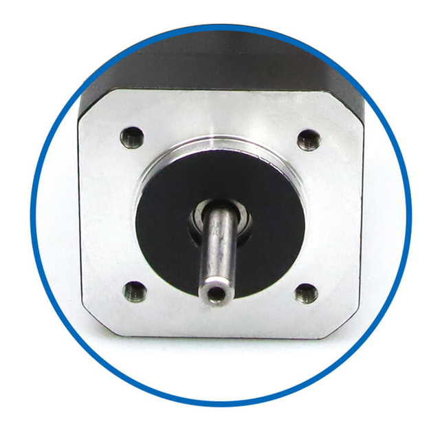
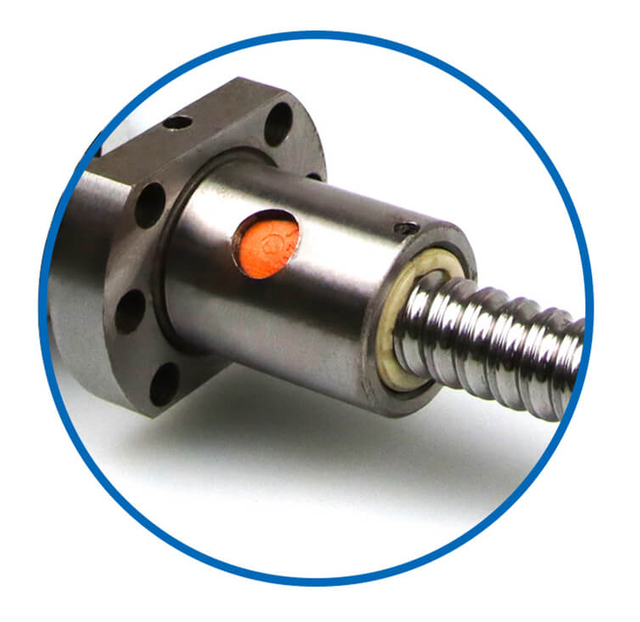
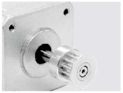
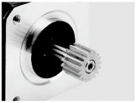
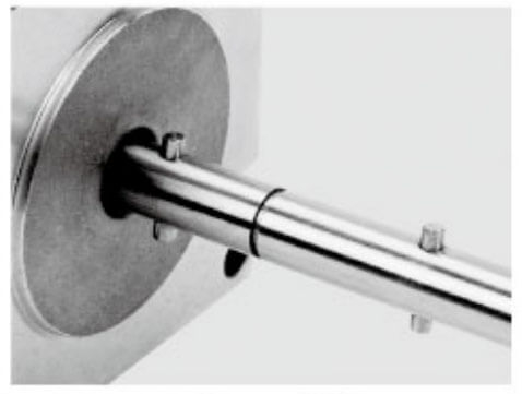
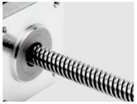
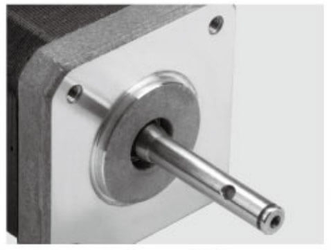
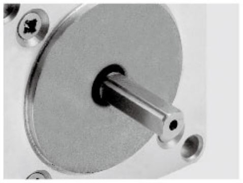
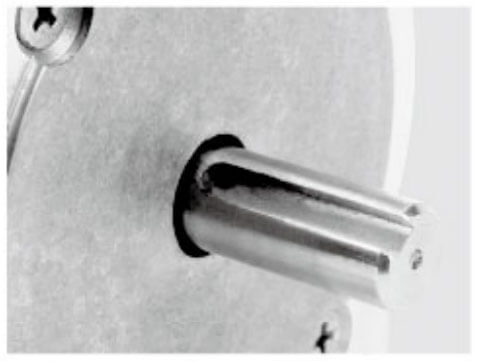
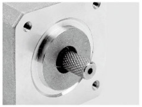
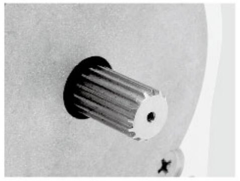
Motor Shaft Customized Service
Jkongmotor offer many different shaft options for your motor as well as customizable shaft lengths to make the motor fit your application seamlessly.
Fundamental Electromagnetic Architecture of Customized Brushless Dc Motor: Stator, Rotor, and Hall Effect Sensors
The physical construction of a brushless motor is deceptively simple yet elegantly optimized. We begin with the stator, the stationary outer shell of the motor. This component is comprised of a stack of high-grade laminated steel sheets, precisely formed to create a series of slots. These slots are wound with copper wire to form multiple electromagnetic coils, which are connected in either a star (wye) or delta configuration. The arrangement and number of these coils, known as poles, are meticulously calculated to produce a specific magnetic characteristic. The stator windings are the active element, where controlled electrical energy is transformed into a rotating magnetic field.
In stark contrast to a brushed motor, the rotor of a BLDC motor contains the permanent magnets. This rotor is the rotating inner component and is typically constructed using high-strength, rare-earth magnetic materials such as Neodymium Iron Boron (NdFeB) or Samarium Cobalt (SmCo). These magnets are arranged with alternating north and south poles and are often embedded within a laminated core or bonded to the rotor's surface. The use of powerful permanent magnets on the rotor eliminates the need for any electrical connections to the moving part, which is a primary source of failure and maintenance in brushed designs.
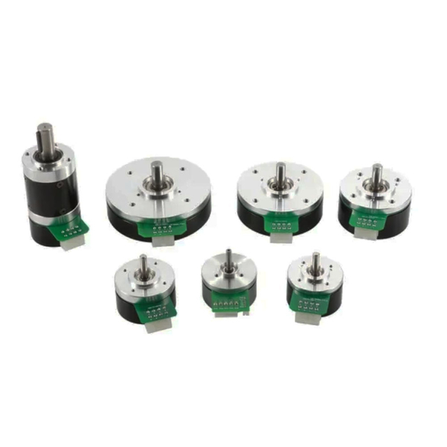
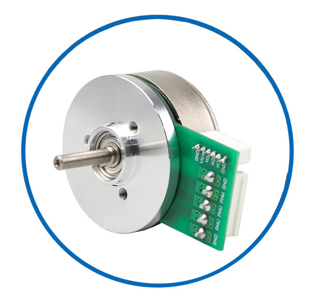
To enable the electronic controller to know the exact positional orientation of the rotor's magnetic field at any given moment, brushless motors integrate position sensors. The most common are Hall-effect sensors, solid-state devices mounted on the stator. As the rotor's permanent magnets pass by, these sensors generate a digital high or low signal, providing a three-bit digital code that uniquely identifies one of six possible 60-degree sectors of rotor position. This feedback is the foundational data for the working principle of brushless motors, allowing the controller to precisely time the energization of the stator coils.
The Core Working Principle of Customized Brushless Dc Motor: Generating the Rotating Magnetic Field (Stator Commutation)
The essence of the brushless motor working principle is the creation of a magnetic field in the stator that continuously "chases" or leads the permanent magnet field of the rotor, causing it to turn. This process is known as electronic commutation or six-step commutation.
We can break down this continuous motion into discrete steps. At any given moment, only two of the three motor phases (typically labeled U, V, and W) are actively energized by the controller. The controller examines the digital signals from the three Hall sensors to determine the rotor's precise sector. Based on this positional data, it calculates which pair of stator windings to energize. For example, it may apply positive DC voltage to phase U and negative DC voltage to phase V, while leaving phase W floating. This current flow through the selected windings generates a specific electromagnetic pole pair in the stator.
This generated stator magnetic field interacts with the permanent magnet field of the rotor. The fundamental law of magnetism—that like poles repel and opposite poles attract—creates a torque on the rotor, forcing it to rotate to align with the stator's field. Just as the rotor begins to move toward alignment, the Hall sensors detect this change in position. The controller, operating at high frequency, instantly switches the energized pair of windings to the next sequence in the commutation table. For instance, it may then energize phase U and phase W. This instantly shifts the stator's magnetic field ahead of the rotor again, creating a new attractive/repulsive force that pulls the rotor forward continuously.
This sequential, digitally-controlled energization of the stator windings creates a trapezoidal back-EMF waveform and is responsible for the motor's rotation. The speed of the motor is directly controlled by the rate at which the controller progresses through this six-step sequence, while the torque is controlled by the amount of current (amperage) supplied to the windings.
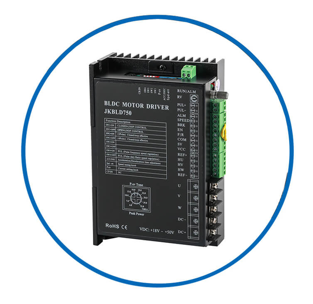
The Indispensable Role of the Electronic Speed Controller (ESC)
The Electronic Speed Controller (ESC) is the computational brain and muscular system of the brushless motor. It is a sophisticated piece of power electronics that performs three non-negotiable functions: power regulation, commutation logic, and closed-loop control.
At its input stage, the ESC receives DC power, typically from a battery or a rectified power supply. This DC power is fed into a circuit known as a three-phase inverter bridge. This bridge consists of six high-power switching transistors, usually MOSFETs or IGBTs, arranged in three pairs (or "legs"). Each motor phase (U, V, W) is connected to the midpoint between one pair of these transistors. By switching these transistors on and off in a precise, high-frequency pattern (Pulse-Width Modulation, or PWM), the ESC can synthesize the alternating current waveforms needed for the motor. It does not simply apply raw DC; it chops the DC into pulses, controlling the effective voltage and current seen by the motor windings.
The commutation logic is a dedicated microprocessor within the ESC that continuously reads the Hall sensor signals. It references a pre-programmed commutation table that maps each of the six possible sensor states to the specific transistor pair that must be switched on. This logic runs in a tight loop, ensuring the switching sequence is perfectly synchronized with the rotor's physical position. Furthermore, the ESC implements the Pulse-Width Modulation (PWM) technique. By rapidly switching the power transistors on and off thousands of times per second and varying the duty cycle (the percentage of "on" time), the controller precisely regulates the average power delivered to the windings. A higher duty cycle results in more current, more magnetic force, and higher torque and speed.
Advanced Control of Customized Brushless Dc Motor: From Trapezoidal to Field-Oriented Control (FOC)
While six-step trapezoidal commutation is effective, it produces torque ripple and audible noise at low speeds. For applications demanding the highest possible efficiency, smoothness, and control bandwidth, we employ Field-Oriented Control (FOC), also known as vector control.
The working principle of brushless motors under FOC is mathematically complex but conceptually elegant. FOC treats the three-phase currents in the stator as a single, rotating vector. The control algorithm uses advanced mathematical transforms (the Clarke and Park transforms) to convert the measured three-phase currents into a two-coordinate rotating reference frame that is locked to the rotor's position. This creates two distinct conceptual current components: the direct current (Id), which controls the magnetic flux, and the quadrature current (Iq), which directly controls torque.
This decoupling is revolutionary. It allows the controller to manage the motor's magnetic field and torque-producing current independently and with extreme precision, much like the separate field and armature controls in a brushed DC motor. The result is buttery-smooth operation from near-zero speed to maximum RPM, minimal torque ripple, and maximized efficiency across the entire speed-torque curve. FOC requires significantly more processing power and often uses higher-resolution positional feedback from an encoder or resolver, but it represents the pinnacle of brushless motor performance in applications such as industrial servo drives, high-end robotics, and electric vehicle traction systems.
Critical Performance Characteristics of Customized Brushless Dc Motor Inherent to the Working Principle
The fundamental brushless motor working principle gives rise to a set of inherent performance advantages that we specify and leverage in design.
High Efficiency and Thermal Management:
The absence of brushes eliminates the primary source of friction and voltage drop (brush contact resistance). Combined with low-resistance stator windings and low-loss laminations, this allows BLDC motors to achieve peak efficiencies of 85-95%. Furthermore, because the windings are on the stationary stator, heat can be dissipated more effectively through the motor housing, often without needing to transfer it across an air gap from a rotating armature. This enables higher continuous power density and more effective cooling via heatsinks or liquid cooling jackets.
High Speed and Dynamic Response:
Without mechanical brushes that can bounce, arc, or wear out at high rotational velocities, brushless motors can operate at significantly higher speeds, often exceeding 100,000 RPM in some high-speed spindle and turbocharger applications. The low rotor inertia (consisting mainly of magnets and a light core) allows for exceptionally fast acceleration and deceleration, providing high dynamic response critical for servo applications.
Long Service Life and Reliability:
The primary wear components in a brushed motor are completely absent. The lifetime of a BLDC motor is therefore determined by the lifespan of its bearings and the integrity of its stator insulation. In clean, cool environments, a BLDC motor can operate for tens of thousands of hours with minimal maintenance. This makes them ideal for inaccessible or safety-critical applications like medical devices, aerospace actuators, and continuous industrial processes.
Low Acoustic and Electrical Noise:
Electronic commutation, especially when implemented with sine-wave commutation or FOC, produces smooth torque with minimal ripple. This results in quieter acoustic operation compared to the audible brush friction and arcing of DC brushes. Additionally, well-designed ESCs can minimize electromagnetic interference (EMI), though proper shielding and filtering remain essential due to the high-frequency switching of the inverter.
Sensorless Control Techniques of Customized Brushless Dc Motor: Operating Without Discrete Position Sensors
While Hall sensors are common, they add cost, complexity, and potential failure points. Advanced sensorless control techniques allow brushless motors to operate without discrete physical position sensors. The working principle of sensorless brushless motors relies on the detection of the Back Electromotive Force (Back-EMF) generated in the unenergized stator winding.
As the permanent magnet rotor spins, it induces a voltage in the stator coils—this is the Back-EMF. Its magnitude is proportional to the rotor's speed, and its zero-crossing points are directly related to the rotor's position relative to the stator phases. A sensorless controller monitors the voltage on the floating phase while the other two are powered. It filters and analyzes this signal to detect the Back-EMF zero-crossing event. This event informs the controller when to commutate to the next step.
The significant challenge with sensorless control is that Back-EMF is zero at standstill and very small at low speeds, making it difficult to detect. Therefore, sensorless algorithms typically use an open-loop startup routine. The controller blindly energizes the windings in a known sequence at a slowly increasing frequency to "kick" the rotor into motion. Once sufficient rotational speed is achieved (typically 5-10% of rated speed), the Back-EMF signal becomes strong enough to detect, and the controller seamlessly transitions to closed-loop sensorless operation. This technique is ubiquitous in cost-sensitive, high-volume applications like cooling fans, appliance motors, and power tools.
Practical Applications of Customized Brushless Dc Motor Dictated by the Working Principle
The specific advantages born from the working principle of brushless motors directly dictate their dominance in key technological sectors.
Electric Mobility and Automotive:
Every modern electric vehicle and hybrid uses high-power BLDC or Permanent Magnet Synchronous Motors (PMSMs, a close variant) for traction. Their high torque density, efficiency over a wide range, and reliability are non-negotiable. Electric Power Steering (EPS) systems also universally employ BLDC motors for their quiet, responsive operation.
Aerospace and Drones:
In multicopter drones, lightweight, high-torque, fast-responding BLDC motors paired with high-speed ESCs provide the precise thrust control necessary for stable flight. In aviation, they are used in cabin air circulation, fuel pumps, and flight control actuators.
Industrial Automation and Robotics:
BLDC motors are the core of modern servo drives, providing the precise position, velocity, and torque control required for CNC machines, robotic arms, and automated guided vehicles (AGVs). Their maintenance-free operation is critical for minimizing production downtime.
Computer Peripherals and Consumer Electronics:
The hard disk drives in computers use ultra-precise, sensorless BLDC spindle motors to rotate platters. Cooling fans in computers, game consoles, and appliances are almost exclusively brushless for silent, reliable operation.
Medical and Laboratory Equipment:
Infusion pumps, surgical hand tools (like drills and saws), and centrifuge drives require smooth, reliable, and controllable torque, making BLDC motors the definitive choice. Their ability to be sterilized and their lack of particulate-generating brushes are added benefits in clean environments.
Key Characteristics & Comparison Between Brushless Motor and Brushed Motor
Here’s how BLDC motors compare to their brushed counterparts:
| Feature | Brushless DC Motor (BLDC) | Brushed DC Motor |
| Commutation | Electronic (via controller) | Mechanical (brushes & commutator) |
| Maintenance | Very low (no brushes to wear out) | Requires periodic brush replacement |
| Efficiency | High (85-90% or more) | Lower (typically 75-80%) |
| Lifespan | Long (limited by bearings) | Shorter (limited by brush wear) |
| Speed/Torque | High-speed capability, smooth torque | Good low-speed torque, torque ripple |
| Cost | Higher (due to controller) | Lower (simple construction) |
| Noise/EMI | Quieter, less electrical noise | Audible brush noise, more sparking/EMI |
Bldc Motor Advantages:
High Reliability & Long Life: No brush wear.
High Efficiency & Power Density: More power and runtime for a given size.
Excellent Speed Control & Dynamic Response: Precise control over a wide speed range.
Low Noise & Minimal EMI: No arcing from brushes.
Brushless Motor Disadvantages:
BLDC motors are ideal for applications requiring reliability, efficiency, and control:
Consumer & IT: Computer cooling fans, drones, appliances (washers, vacuums).
Industrial: CNC machines, conveyor systems, industrial robots.
Transportation: Electric vehicles (traction motors), electric bicycles, aircraft systems.
Medical: Precision equipment like pumps and surgical tools.
BLDC vs. PMSM: While often used interchangeably, a Permanent Magnet Synchronous Motor (PMSM) has a sinusoidal back-EMF and is driven by sinusoidal currents for ultra-smooth operation (common in high-end industrial/automotive uses). A typical BLDC has a trapezoidal back-EMF and uses simpler, blocky commutation.
Control Methods: Control can be sensored (using Hall-effect sensors for position) or sensorless (estimating position from motor voltage/current, common in fans and drones).
In summary, the BLDC motor is a superior choice for modern, high-performance applications due to its efficiency, reliability, and controllability, despite its more complex drive system.
Conclusion: The Paradigm of Efficient Electromechanical Conversion
The working principle of brushless motors is a masterclass in the integration of electromagnetism, materials science, and digital signal processing. By replacing the crude mechanical switching of brushes with the exquisite precision of electronic commutation, engineers have unlocked new realms of performance, durability, and control. We have moved from a paradigm of simple voltage application to one of intelligent current vector management. From the fundamental six-step Hall sensor commutation to the advanced mathematics of Field-Oriented Control and the clever algorithms of sensorless operation, the brushless DC motor stands as a testament to the power of solid-state electronics to perfect a classical mechanical device. Its working principle is not just a method of causing rotation; it is the foundational logic for a new era of efficient, intelligent, and reliable motion control that powers our most advanced technologies.