Introduction to DC Motor Torque Control
Torque control in a DC motor is fundamentally about managing armature current, since torque is directly proportional to current when magnetic flux is constant. Modern DC motor products achieve this through advanced drive systems with PWM and closed-loop current regulation, enabling accurate and responsive torque performance. From a factory and customization perspective, torque control requirements influence key design choices — including windings, magnet materials, control electronics, and thermal design — and can be tailored for specific applications such as robotics, industrial automation, and precision motion systems. Comprehensive testing and calibration ensure that customized torque characteristics meet customer specifications and real-world performance targets.
Torque control in a DC motor lies at the heart of modern electromechanical systems. From precision robotics and industrial automation to electric vehicles and medical devices, the ability to regulate torque accurately determines performance, efficiency, and operational reliability. We examine how torque is generated, measured, and precisely controlled in DC motors, presenting a complete engineering-level perspective grounded in electromagnetic principles and real-world drive technologies.
Fundamental Principle: The Relationship Between Torque and Current
At its core, DC motor torque is directly proportional to armature current. This fundamental relationship defines every practical torque control strategy.
The electromagnetic torque equation is expressed as:
T = k × Φ × I
Where:
T = electromagnetic torque
k = motor construction constant
Φ = magnetic flux per pole
I = armature current
In most industrial DC motors, the magnetic flux Φ remains essentially constant. Therefore, controlling torque reduces to controlling current. This direct proportionality is what makes DC motors exceptionally suitable for high-precision torque applications.
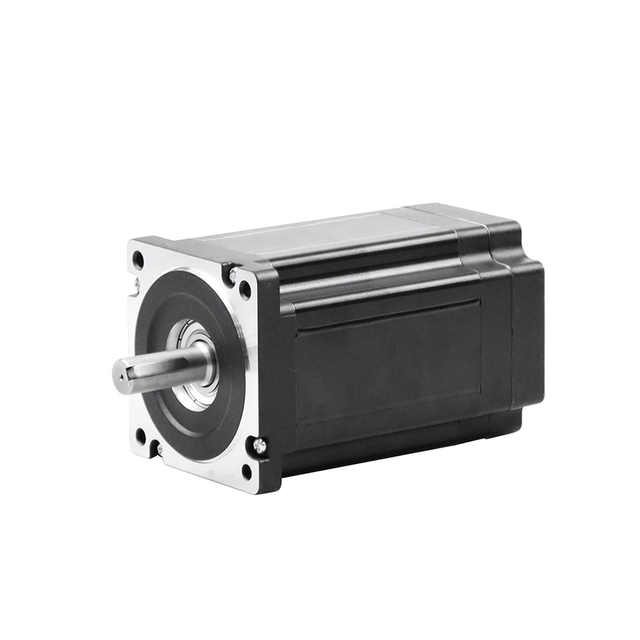
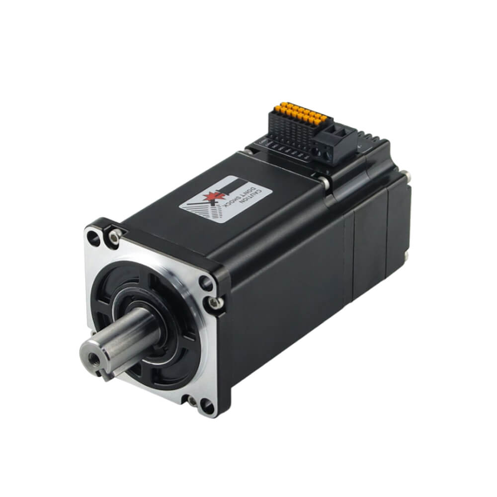
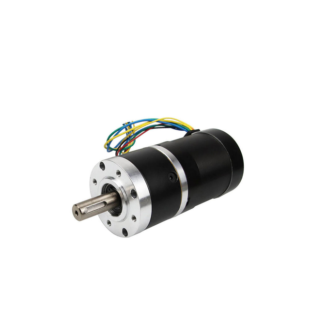
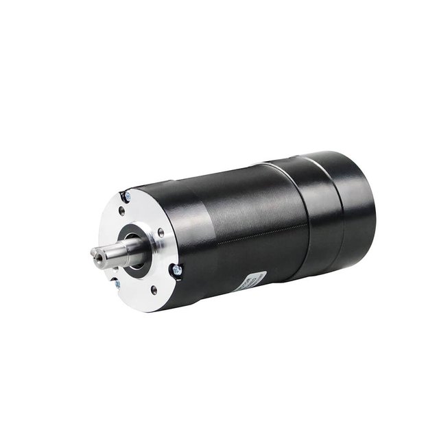
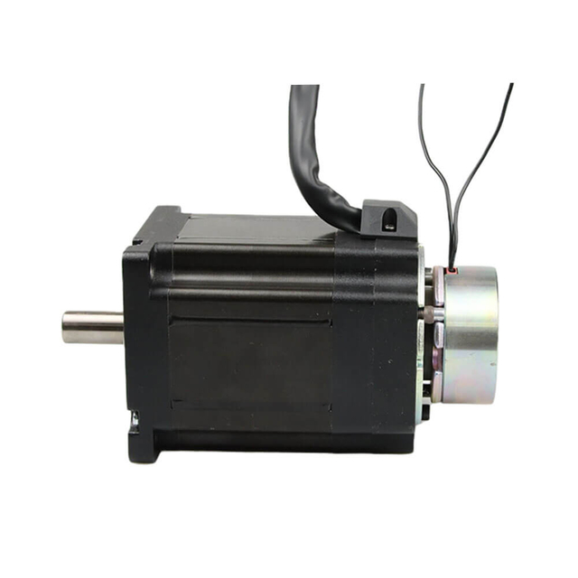
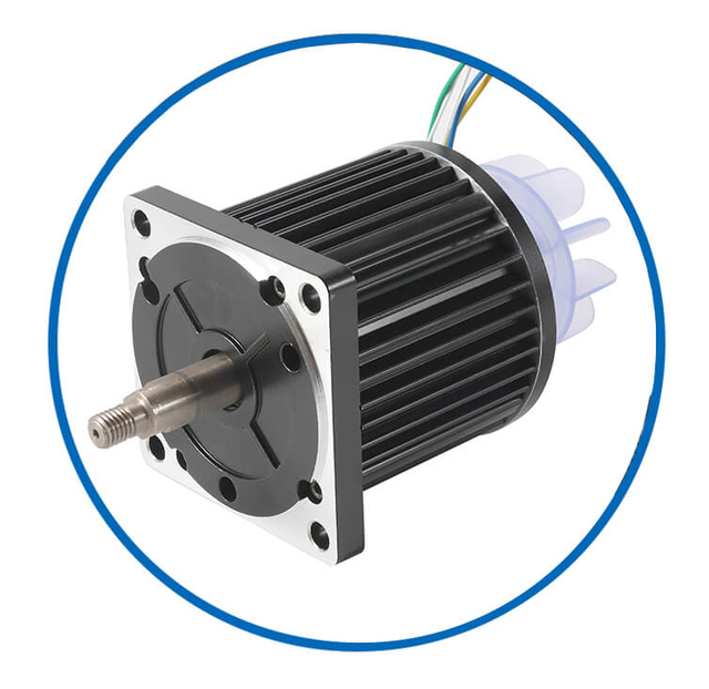
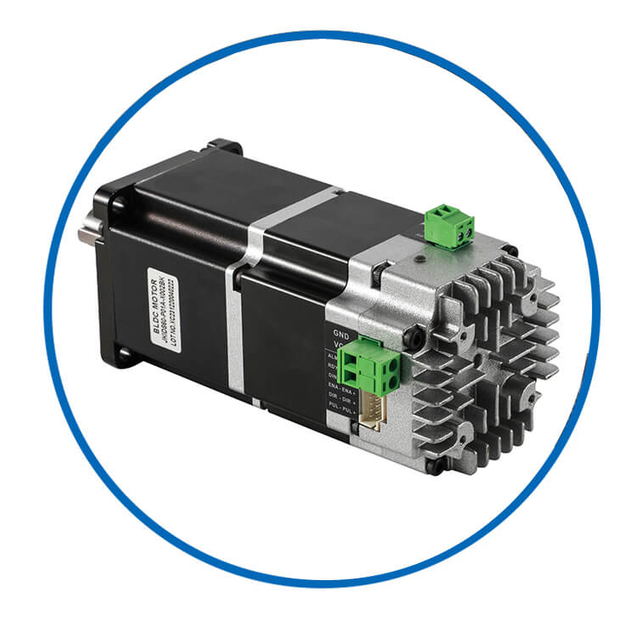
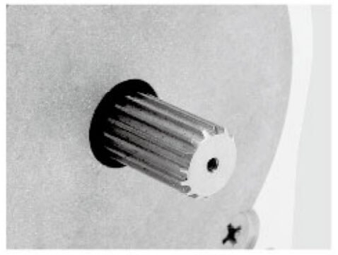
Jkongmotor ODM OEM Customized Bldc Motor Types
Bldc Motor Customized Service
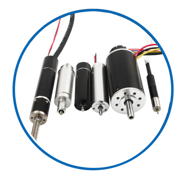
As a professional brushless dc motor manufacturer with 13 years in china, Jkongmotor offer various bldc motors with customized requirements, including 33 42 57 60 80 86 110 130mm, additionally, gearboxes, brakes, encoders, brushless motor drivers and integrated drivers are optional.
![bldc motor supplier]() | ![bldc motor supplier]() | ![bldc motor supplier]() | ![bldc motor supplier]() | ![bldc motor supplier]() | Professional custom brushless motor services safeguard your projects or equipment. No Brushes – Reduced Maintenance and Increased Lifespan High Efficiency and Low Power Loss High Torque-to-Weight Ratio Precise Speed and Position Control Quiet and Smooth Operation Wide Speed Range and Dynamic Performance Excellent Thermal Management Customizable Designs and Modular Configurations Multiple Control Methods Integration with Digital Interfaces and Sensors |
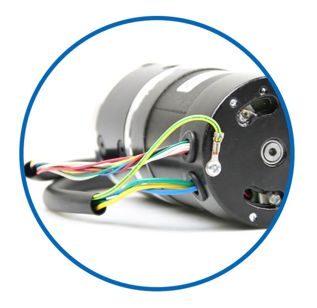
| Wires | Covers | Fans | Shafts | Integrated Drivers |
![bldc motor supplier]() | ![bldc motor supplier]() | ![bldc motor supplier]() | ![bldc motor supplier]() | ![bldc motor supplier]() |
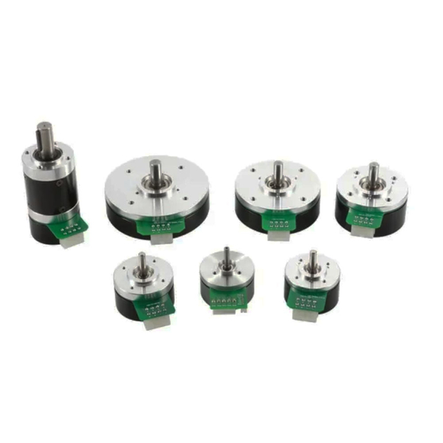
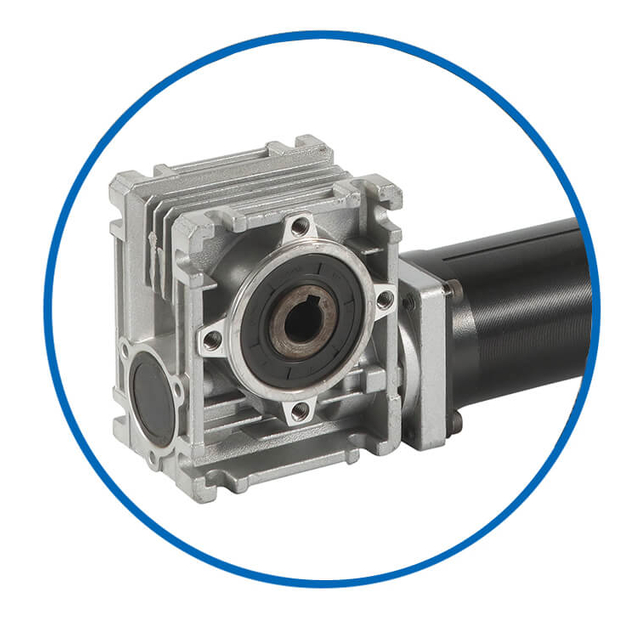
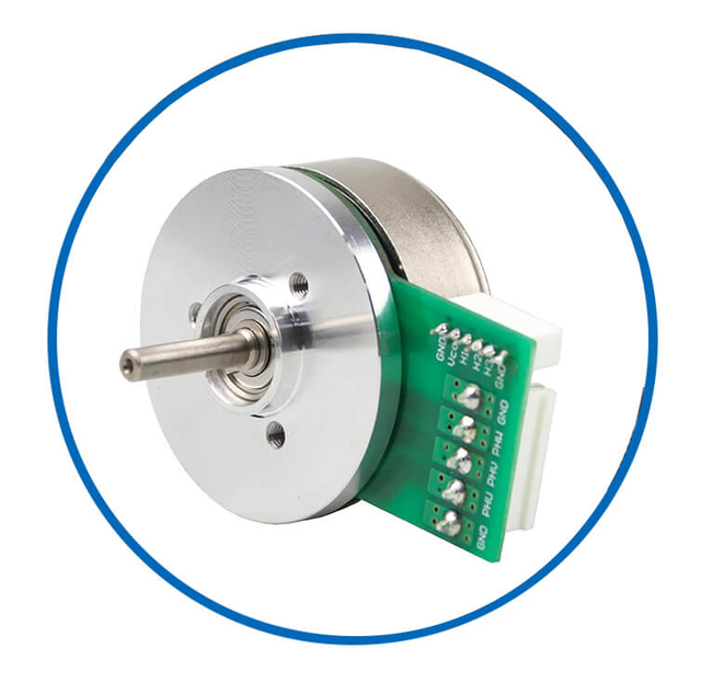
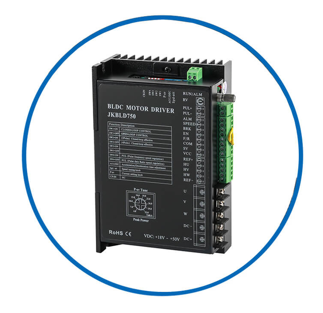
| Brakes | Gearboxes | Out Rotors | Coreless Dc | Drivers |
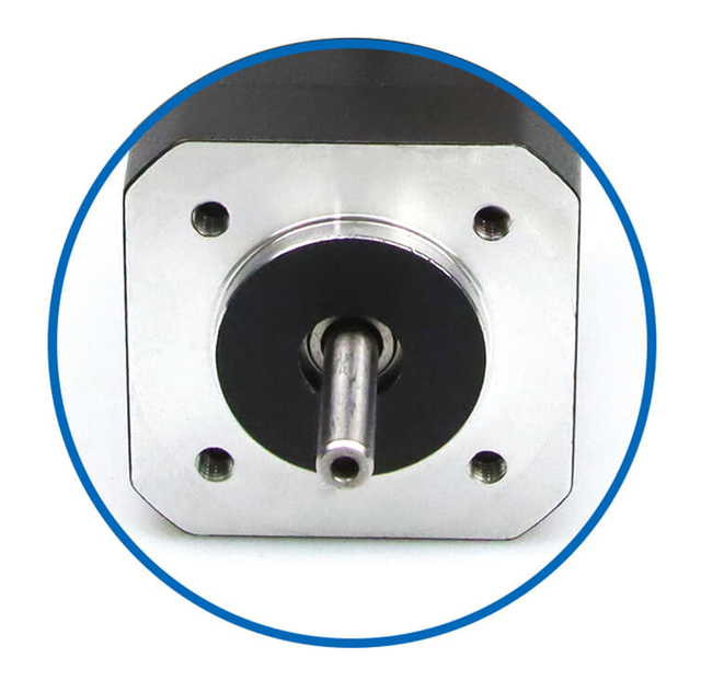
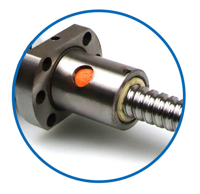
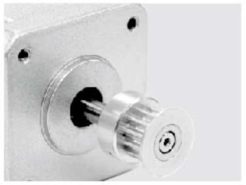
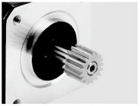
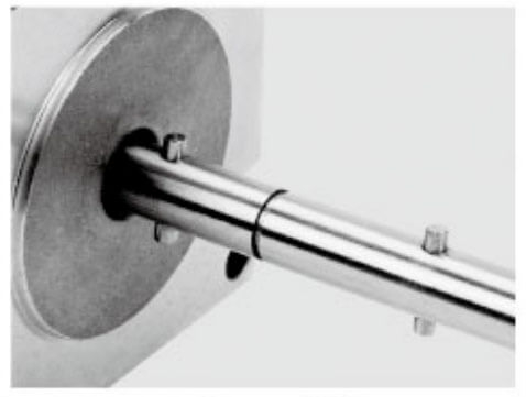
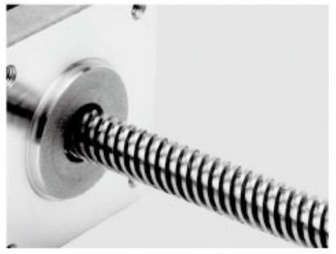
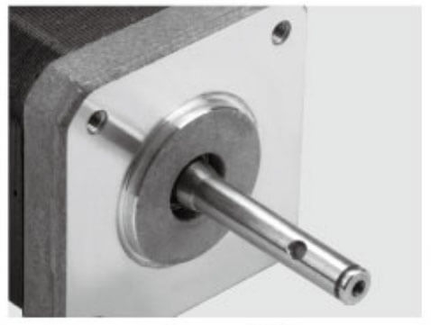
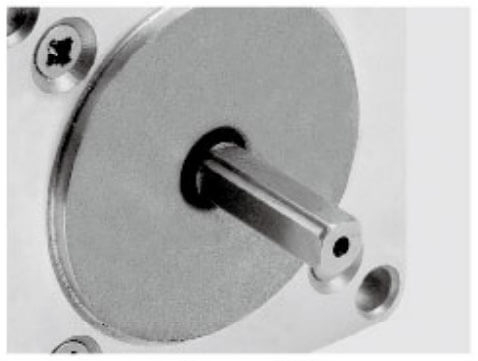
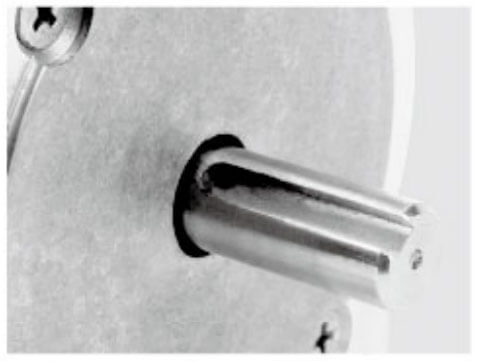
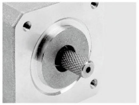
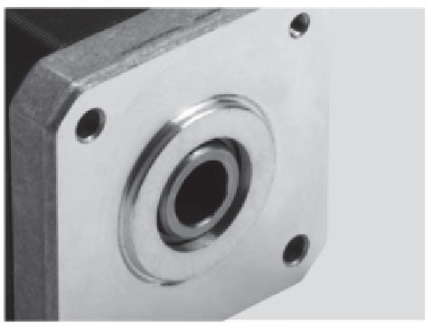
Motor Shaft Customized Service
Jkongmotor offer many different shaft options for your motor as well as customizable shaft lengths to make the motor fit your application seamlessly.
How DC Motors Physically Produce Torque
DC motors produce torque through a direct interaction between electric current and a magnetic field, based on the fundamental law of electromagnetism known as the Lorentz force principle. When a current-carrying conductor is placed inside a magnetic field, it experiences a mechanical force. In a DC motor, this force is converted into rotational motion, which appears at the shaft as usable torque.
1. Electromagnetic Force as the Source of Torque
Inside a DC motor, the stator creates a stationary magnetic field, either by permanent magnets or field windings. The rotor (armature) contains multiple conductors arranged in coils. When DC current flows through these conductors, each one experiences a force given by:
F = B × I × L
Where:
F is the force on the conductor
B is magnetic flux density
I is current
L is active conductor length
The direction of this force is determined by Fleming’s Left-Hand Rule. Conductors on opposite sides of the rotor experience forces in opposite directions, forming a couple that produces rotation.
2. Conversion of Linear Force into Rotational Torque
The forces acting on the armature conductors are offset from the motor shaft. Because they act at a radius, they generate a moment of force, or torque:
T = F × r
Where:
All active conductors contribute to the total torque. The combined effect of dozens or hundreds of conductors results in smooth, continuous rotational torque at the output shaft.
3. Role of the Commutator in Maintaining Continuous Torque
If current direction remained fixed, the rotor would stop when it aligned with the magnetic field. The commutator and brushes prevent this by automatically reversing current direction in the armature coils every half-turn. This reversal ensures that the electromagnetic forces always act in the same rotational direction, maintaining uninterrupted torque production.
The commutator therefore performs three critical functions:
Keeps torque direction constant
Enables continuous rotation
Minimizes dead zones in torque output
4. Magnetic Flux and Torque Strength
The magnitude of torque depends directly on the strength of the magnetic field. Stronger flux increases the electromagnetic force on each conductor, resulting in higher torque for the same current.
This relationship is expressed as:
T = k × Φ × I
Where:
Because flux is usually held constant, torque becomes linearly proportional to current, making DC motors extremely predictable and controllable.
5. Distributed Conductors and Torque Smoothing
Modern DC motors distribute conductors across many slots around the armature. At any moment, some conductors are in optimal positions to generate force. This overlapping action ensures:
The combined electromagnetic effect produces a nearly constant net torque over a full rotation.
6. Mechanical Output at the Shaft
All electromagnetic torque developed in the armature is transmitted through the rotor core to the motor shaft. Bearings support the shaft and allow low-friction rotation. The resulting mechanical output is available to drive:
Gearboxes
Belts and pulleys
Lead screws
Wheels and pumps
This is where electrical energy has been fully converted into controlled mechanical force.
Summary
DC motors physically produce torque when current-carrying armature conductors interact with a magnetic field, generating forces that create a rotating moment around the shaft. Through precise commutation, distributed windings, and stable magnetic flux, these forces combine to deliver continuous, controllable, and high-efficiency torque suitable for everything from micro-devices to heavy industrial machinery.
Primary Torque Control Method: Armature Current Regulation
The primary and most effective way to control torque in a DC motor is through armature current regulation. This method is based on a fundamental electromagnetic principle: motor torque is directly proportional to armature current when magnetic flux is constant. Because of this linear relationship, precise control of current translates directly into precise control of torque.
1. Torque–Current Relationship
The electromagnetic torque of a DC motor is defined by:
T = k × Φ × Iₐ
Where:
In most practical DC motor systems, the field flux Φ is kept constant. Under this condition, torque becomes strictly proportional to armature current. Doubling the current doubles the torque. Reducing the current reduces torque proportionally. This predictable behavior is what makes DC motors exceptionally suitable for torque-controlled applications.
2. Why Armature Current Is the Best Control Variable
Armature current is the direct cause of torque production. Unlike speed or voltage, current reflects the instantaneous electromagnetic force inside the motor. By regulating current, the drive system controls torque independently of speed, enabling:
Full rated torque at zero speed
Instant response to load changes
Accurate force and tension control
Stable low-speed operation
This is essential in applications such as hoists, extruders, robotics, conveyors, and electric traction systems.
3. How Armature Current Is Regulated
Modern DC drives use closed-loop current control. The actual armature current is continuously measured using shunt resistors, Hall-effect sensors, or current transformers. This measured value is compared with a torque command signal. Any difference (error) is processed by a high-speed controller, which adjusts the drive output voltage to force the current to the desired level.
The control process follows this sequence:
Torque command sets a current reference
Current sensor measures real armature current
Controller calculates the error
PWM power stage adjusts armature voltage
Current is driven precisely to the target value
This loop typically operates in the microsecond to millisecond range, making it the fastest and most stable loop in the entire motor control system.
4. Role of PWM Drives in Current Control
Pulse Width Modulation (PWM) drives regulate armature current by rapidly switching the supply voltage on and off. By varying the duty cycle, the controller adjusts the average voltage applied to the armature, which determines how quickly current rises or falls through the motor’s inductance.
PWM-based current regulation provides:
The armature inductance smooths the current waveform, allowing the motor to experience nearly continuous torque even though the supply is switching.
5. Protection and Stability in Current-Based Torque Control
Because current directly determines torque and heating, armature current regulation also serves as the foundation of motor protection. Modern drives integrate:
Peak current limiting
Thermal modeling
Short-circuit protection
Stall detection
Overload profiles
These features ensure that maximum torque is delivered safely, without exceeding thermal or magnetic limits.
6. Performance Advantages of Armature Current Torque Control
Armature current regulation delivers several critical advantages:
Linear and predictable torque output
High torque accuracy
Excellent low-speed controllability
Rapid dynamic response
Smooth startup and braking
Superior disturbance rejection
This makes current-based torque control the dominant strategy in DC servo systems, traction drives, metal processing equipment, elevators, and automation machinery.
Summary
Armature current regulation is the core method of torque control in DC motors because current is the direct physical cause of electromagnetic torque. By precisely measuring and controlling armature current through closed-loop electronic drives, DC motors can produce accurate, responsive, and stable torque across their entire operating range, independent of speed and load conditions.
Voltage Control and Its Role in Torque Regulation
Although torque in a DC motor is directly determined by armature current, voltage control plays a critical supporting role. Armature voltage is the variable that actually forces current to change inside the motor. By regulating voltage, the drive system controls how quickly and how smoothly current reaches its commanded value, which directly affects torque response, stability, and efficiency.
1. The Electrical Dynamics Behind Voltage Control
The armature circuit of a DC motor follows the equation:
Vₐ = E_b + IₐRₐ + Lₐ(dIₐ/dt)
Where:
This equation shows that voltage must overcome three factors:
Torque is proportional to current, but voltage determines how current is established and maintained, especially during acceleration, deceleration, and load disturbances.
2. How Voltage Control Influences Torque Response
When load torque suddenly increases, motor speed momentarily drops, reducing back EMF. The drive responds by raising armature voltage, allowing current to rise quickly. The increased current produces higher torque, restoring equilibrium.
Voltage control therefore governs:
Torque rise time
Dynamic stiffness
Transient stability
Disturbance rejection
A drive with fast and precise voltage modulation can build current rapidly, enabling instant torque delivery.
3. PWM Voltage Control in Modern DC Drives
Modern DC motor controllers regulate voltage using Pulse Width Modulation (PWM). The power devices switch the supply on and off at high frequency. By adjusting the duty cycle, the controller sets the average armature voltage.
PWM voltage control provides:
The motor’s inductance filters the switching waveform, converting it into a smooth current that produces stable torque.
4. Voltage as the Actuator in the Torque Loop
In closed-loop torque control systems, current is the controlled variable, but voltage is the manipulated variable. The controller continuously adjusts armature voltage to force current to match the torque command.
This makes voltage control responsible for:
Enforcing current commands
Compensating for back EMF changes
Correcting load disturbances
Limiting current overshoot
Stabilizing torque output
Without precise voltage control, accurate current and torque regulation would not be possible.
5. Voltage Control and Torque Smoothness
High-quality voltage regulation minimizes:
By maintaining a steady electrical environment, voltage control contributes to smooth mechanical output, which is essential in robotics, medical devices, and precision manufacturing equipment.
6. Interaction Between Voltage, Speed, and Torque
As speed increases, back EMF rises and opposes the applied voltage. To maintain the same torque at higher speeds, the controller must increase voltage to sustain the required current. Conversely, at low speeds, only a small voltage is needed to generate high current, allowing DC motors to produce full rated torque even at zero speed.
Voltage control therefore enables torque regulation across the entire operating range.
Summary
Voltage control does not directly set torque, but it is the means by which torque is enforced. By precisely regulating armature voltage, the drive system controls how current builds and stabilizes inside the motor. This allows DC motors to deliver fast, smooth, and accurate torque under changing speed and load conditions, making voltage control an essential component of all modern torque regulation systems.
Field Control and Flux-Based Torque Modulation
Although most DC motors operate at constant field flux, field current adjustment provides an additional method of torque modulation.
Increasing field current strengthens the magnetic flux, producing greater torque per ampere. Decreasing field current reduces torque while allowing higher speeds under constant voltage.
Field-based torque control is widely used in:
However, field control responds slower than armature current regulation and is typically applied for coarse torque shaping rather than fine dynamic control.
Closed-Loop Torque Control Systems
Modern DC drives implement nested control loops:
Inner current loop (torque loop)
Outer speed loop
Optional position loop
The torque loop is always the fastest. It stabilizes the electromagnetic behavior of the motor, making the entire drive system behave as a pure torque actuator.
Benefits of Closed-Loop Torque Control
High torque accuracy
Fast transient response
Automatic load compensation
Reduced mechanical stress
Improved low-speed performance
This structure allows DC motors to deliver rated torque at zero speed, a defining advantage in servo and traction applications.
Brushed DC Motors
Torque control in brushed DC motors relies on:
They offer excellent controllability, simple electronics, and predictable response.
In BLDC motors, torque control is achieved by:
Electronic commutation
Phase current regulation
Rotor position feedback
Although construction differs, the governing law remains identical:
Torque is proportional to phase current interacting with magnetic flux.
Advanced drives use vector control to align current precisely with the magnetic field, producing constant torque with minimal ripple.
Role of PWM Drives in Torque Regulation
Pulse Width Modulation (PWM) drives play a central role in modern DC motor torque regulation. While torque is directly proportional to armature current, PWM drives provide the high-speed voltage control necessary to shape, regulate, and stabilize that current. By rapidly switching the supply voltage on and off and precisely adjusting the duty cycle, PWM drives enable **fast, efficient, and highly accurate torque control PWM drives enable fast, efficient, and highly accurate torque control across the entire operating range of a DC motor.
1. PWM as the Core Voltage Control Mechanism
A PWM drive does not vary voltage by dissipating energy, but by time-proportioning the supply voltage. Power semiconductors such as MOSFETs or IGBTs switch at high frequency, typically from several kilohertz to tens of kilohertz. The ratio of ON time to OFF time—the duty cycle—determines the effective average voltage applied to the motor.
This high-speed voltage modulation allows the controller to:
Force armature current to follow the torque command
Overcome back EMF at higher speeds
Compensate instantly for load disturbances
Minimize electrical losses
PWM therefore acts as the electrical actuator of the torque control system.
2. Enabling Precise Armature Current Regulation
Because the motor armature is inductive, it naturally smooths the switched voltage waveform into a near-continuous current. The PWM drive exploits this behavior by adjusting duty cycle so that current is regulated to the desired level.
This closed-loop current control provides:
Without PWM, such fine and fast current regulation would not be practical in modern systems.
3. Fast Dynamic Torque Response
Torque control performance depends on how quickly the system can change current. PWM drives operate at high switching frequencies and are controlled by fast digital processors. This allows them to modify voltage in microseconds, producing:
Immediate torque buildup during acceleration
Rapid torque reduction during braking
Precise response to external force disturbances
Excellent low-speed and stall behavior
This fast electrical response is essential in robotics, traction systems, CNC machines, and servo-controlled equipment.
4. Torque Smoothness and Ripple Reduction
PWM drives significantly reduce torque ripple by:
Providing fine voltage resolution
Enabling high-bandwidth current loops
Allowing digital filtering and compensation
Supporting optimized commutation timing
The result is smooth current flow and stable electromagnetic force, which minimizes vibration, acoustic noise, and mechanical stress.
5. Regenerative Torque and Four-Quadrant Operation
Modern PWM drives support full four-quadrant operation, meaning they can control torque in both rotational directions and during both motoring and braking.
This allows:
Controlled deceleration
Regenerative energy recovery
Tension control in winding systems
Safe handling of overhauling loads
PWM bridges manage current flow in either direction, turning the motor into a precisely regulated torque source or load.
6. Protection and Torque Limiting Functions
PWM drives integrate protective torque-related features, including:
Peak current limiting
Thermal modeling
Stall detection
Short-circuit protection
Soft-start torque ramps
These features ensure that maximum torque is delivered safely and consistently, preventing damage to motors, gearboxes, and mechanical structures.
7. Energy Efficiency in Torque Control
Because PWM drives switch devices either fully on or fully off, power dissipation is minimal. This results in:
Efficient power handling allows higher continuous torque ratings without excessive heat generation.
Summary
PWM drives are the technological foundation of modern DC motor torque regulation. By providing high-speed, high-resolution voltage control, they enable precise armature current regulation, fast torque response, smooth mechanical output, regenerative operation, and robust protection. Through PWM technology, DC motors become high-performance, programmable torque actuators capable of meeting the demanding requirements of contemporary industrial and motion control applications.
Torque Sensors and Estimation Techniques
Torque can be controlled by direct measurement or electrical estimation.
Direct Torque Measurement
Used where absolute torque validation is required, such as aerospace testing or calibration systems.
Torque Estimation
Most industrial drives calculate torque using:
Estimation offers high-speed feedback without mechanical complexity, making it the dominant industrial solution.
Thermal and Magnetic Constraints in Torque Control
Torque control always operates within thermal and magnetic limits.
Excessive current causes copper losses and insulation degradation
Excessive flux causes core saturation
Torque transients induce mechanical fatigue
Professional DC torque control systems integrate:
This ensures maximum torque output without compromising service life.
Torque Ripple Reduction Strategies
Even in DC motors, torque ripple can arise from:
Slotting effects
Commutation overlap
PWM harmonics
Mechanical eccentricity
Advanced torque control minimizes ripple through:
High-frequency current loops
Optimized commutation timing
Smoothing inductors
Precision rotor balancing
Digital compensation filters
The result is stable torque delivery, essential in medical devices, machine tools, and semiconductor equipment.
Applications Where Precise DC Torque Control Is Critical
Precise torque control is one of the defining strengths of DC motor systems. Because torque is directly proportional to armature current, DC motors can be regulated to behave as accurate, repeatable force actuators. This capability is essential in applications where even small torque deviations can affect product quality, safety, efficiency, or mechanical integrity. Below are the major fields where high-precision DC torque control is not optional, but fundamental.
1. Electric Vehicles and Traction Systems
In electric vehicles, rail traction, and automated guided vehicles (AGVs), torque control determines:
Acceleration and deceleration behavior
Hill-climbing capability
Regenerative braking performance
Wheel slip and traction stability
Precise DC torque control enables smooth starts, powerful low-speed pulling force, controlled braking, and efficient energy recovery. Without accurate torque regulation, vehicles suffer from jerky motion, reduced efficiency, and mechanical stress.
2. Industrial Robotics and Automation
Robotic arms, collaborative robots, and automated assembly systems rely on torque control to manage:
DC torque control allows robots to apply exact, repeatable forces, essential for welding, polishing, pick-and-place, screw driving, and medical automation. It also enables compliance control, where robots adapt torque output dynamically when encountering resistance.
3. CNC Machines and Precision Manufacturing
Machine tools such as CNC mills, lathes, grinders, and laser cutters require stable torque to maintain:
Constant cutting force
Surface finish quality
Dimensional accuracy
Tool life
Precise DC torque control prevents chatter, reduces tool wear, and ensures consistent material removal, even when workpiece hardness or cutting depth changes during operation.
4. Hoists, Cranes, and Elevator Systems
Vertical motion systems demand extremely reliable torque control to handle:
Heavy load lifting
Controlled lowering
Anti-rollback protection
Emergency stopping
DC motors regulated by current-based torque control deliver full rated torque at zero speed, making them ideal for holding loads, starting under heavy weight, and performing smooth low-speed positioning without mechanical shock.
5. Winders, Unwinders, and Tension Control Equipment
In industries such as packaging, textiles, paper, film, cable, and metal foil processing, torque control directly determines web tension.
Precise torque control is critical to:
Prevent tearing or wrinkling
Maintain constant tension
Ensure uniform winding density
Protect delicate materials
DC torque drives automatically compensate for changing roll diameters and speeds, maintaining stable, repeatable tension throughout the entire production cycle.
6. Medical and Laboratory Equipment
Medical devices demand extremely fine torque resolution and reliability. Examples include:
Accurate DC torque control ensures precise force delivery, patient safety, ultra-smooth motion, and silent operation. In these environments, even minor torque ripple can compromise outcomes.
7. Conveyors and Material Handling Systems
Conveyors, sorters, and pallet handling equipment rely on torque regulation to manage:
Load sharing across multiple drives
Smooth startup of heavy belts
Jam detection
Product spacing and indexing
Torque-controlled DC drives allow conveyors to adapt instantly to load variations, reducing mechanical wear and improving throughput.
8. Extruders, Mixers, and Process Machinery
Process industries depend on torque to control:
Material compression
Shear forces
Flow consistency
Reaction stability
In plastics, food, pharmaceuticals, and chemicals, torque reflects real-time process conditions. DC torque control enables closed-loop process regulation, where motor torque becomes a direct indicator of material behavior.
9. Aerospace and Defense Systems
Torque control in aerospace actuators supports:
These systems require exceptional reliability, fast dynamic response, and exact force output under widely varying environmental conditions.
10. Test Benches and Dynamometer Systems
In motor testing, component validation, and fatigue analysis, torque must be regulated with extreme precision to:
Simulate real operating loads
Reproduce duty cycles
Measure efficiency and performance
Validate mechanical durability
DC torque-controlled drives allow engineers to apply exact, programmable mechanical loads, turning electric motors into highly accurate mechanical instruments.
Summary
Precise DC torque control is critical wherever force accuracy, dynamic response, safety, and process consistency are essential. From electric transportation and robotics to medical technology and high-end manufacturing, DC torque control transforms motors into intelligent force generators, capable of delivering predictable, stable, and finely regulated mechanical output across the most demanding applications.
Torque in a DC motor is controlled fundamentally by regulating armature current under stable magnetic flux. Through modern electronic drives, feedback loops, and digital signal processing, DC motors achieve exceptional torque precision, fast dynamic response, and broad controllability.
By combining electromagnetic principles with high-speed power electronics, torque control transforms DC motors into predictable, programmable force generators capable of serving the most demanding applications across modern industry.
FAQs of General Torque Control Principles
1. What is torque control in a DC motor?
Torque control refers to regulating the motor’s output force by controlling the armature current, since torque is proportional to current in DC motors.
2. How is torque generated in a DC motor?
Torque comes from the interaction between magnetic flux and armature current, following the equation T = k × Φ × I.
3. Why is armature current central to torque control?
Because flux Φ is usually kept constant in most DC motor designs, torque becomes directly proportional to current.
4. What role does the commutator play in torque production?
The commutator reverses current direction to maintain continuous and consistent torque output.
5. How does magnetic flux affect torque?
Stronger flux increases torque for a given current; product variants with higher flux materials yield higher torque outputs.
FAQs of Control Methods & Motor Drives
6. What are common torque control methods in DC motors?
7. What is PWM torque control?
Pulse-Width Modulation modulates effective voltage to regulate current, enabling precise torque control.
8. How does a closed-loop current controller improve torque accuracy?
It continuously measures actual current and adjusts drive output to match a torque setpoint.
9. Can torque be controlled independently of speed?
Yes — a dedicated current loop enables torque control even when speed varies due to load changes.
10. Is torque control important for servo applications?
Yes, high-precision servo systems rely on torque control as a fundamental layer beneath speed and position loops.
FAQs of Customization & Product Variation
11. Can torque characteristics be customized in factory production?
Yes — parameters like winding design, magnet strength, and current limits can be tailored to specific torque requirements.
12. What motor types offer best torque control for your product?
Brushed DC, brushless DC (BLDC), and DC servo motors are all customizable for torque control based on application needs.
13. How can a manufacturer increase stall torque on a DC motor?
By using optimized windings, stronger magnets, and higher current capacity.
14. Does gearbox integration affect torque control?
Integrated gearboxes multiply output torque for the same motor torque, offering mechanical torque enhancement.
15. Can factory firmware be tuned for torque performance?
Yes — drive firmware can be optimized for options like torque limiting, soft start, and dynamic torque responses.
FAQs of Product Calibration & Testing
16. How is torque verified in production testing?
Torque is inferred from armature current measurements and calibrated against motor constants in controlled test rigs.
17. What product specifications matter for torque control?
Rated current, torque constant (k), magnetic flux strength, and winding resistance are key specs.
18. Are thermal limits relevant to torque control?
Yes — higher torque means higher current and heat, so thermal management must be engineered accordingly.
19. Can customers specify torque control features?
Yes — options like torque sensing feedback, current limit settings, and control interface types can be custom-specified.
20Do customized DC motors support digital control?
Many bespoke designs include digital interfaces for torque commands (analog, PWM, CAN, RS485, etc.).