Brushless DC (BLDC) motors are widely used in industrial automation, electric vehicles, robotics, medical equipment, and consumer electronics due to their high efficiency, long service life, precise control, and low maintenance. BLDC motor types are commonly classified based on back-EMF waveform, rotor structure, stator configuration, mechanical design, and application requirements.
Below is a clear, structured, and engineering-focused overview of BLDC motor types.
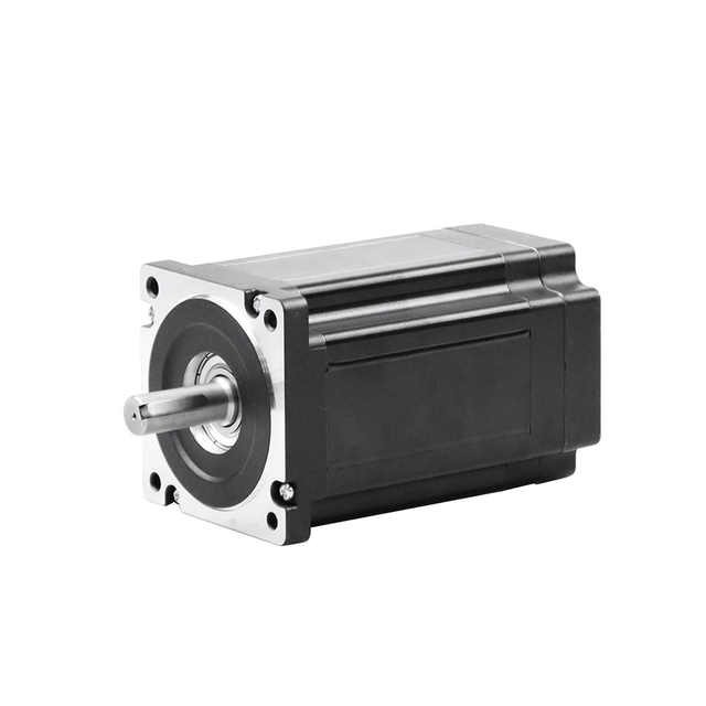
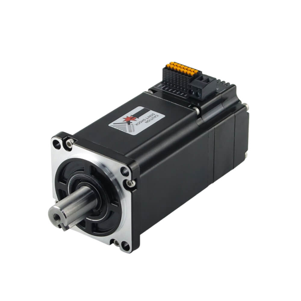
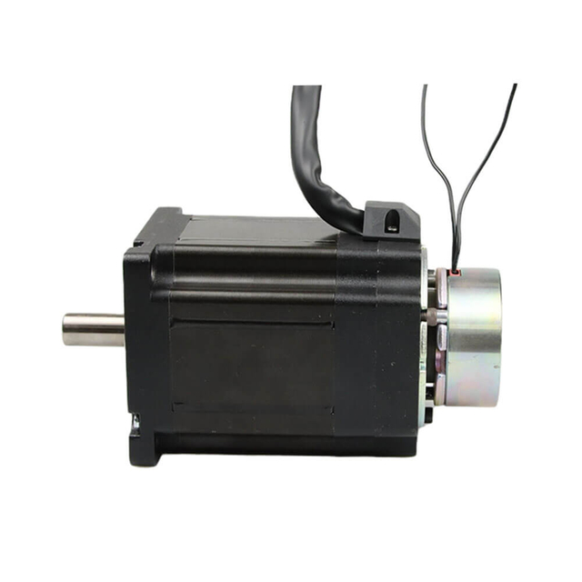
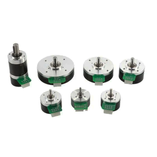
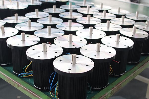
Bldc Motor Customized Service
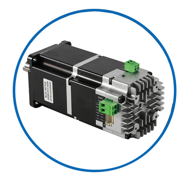
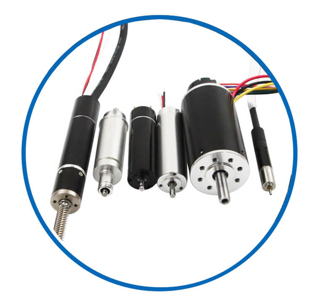
As a professional brushless dc motor manufacturer with 13 years in china, Jkongmotor offer various bldc motors with customized requirements, including 33 42 57 60 80 86 110 130mm, additionally, gearboxes, brakes, encoders, brushless motor drivers and integrated drivers are optional.
![bldc motor supplier]() | ![bldc motor supplier]() | ![bldc motor supplier]() | ![bldc motor supplier]() | ![bldc motor supplier]() | Professional custom brushless motor services safeguard your projects or equipment. No Brushes – Reduced Maintenance and Increased Lifespan High Efficiency and Low Power Loss High Torque-to-Weight Ratio Precise Speed and Position Control Quiet and Smooth Operation Wide Speed Range and Dynamic Performance Excellent Thermal Management Customizable Designs and Modular Configurations Multiple Control Methods Integration with Digital Interfaces and Sensors |
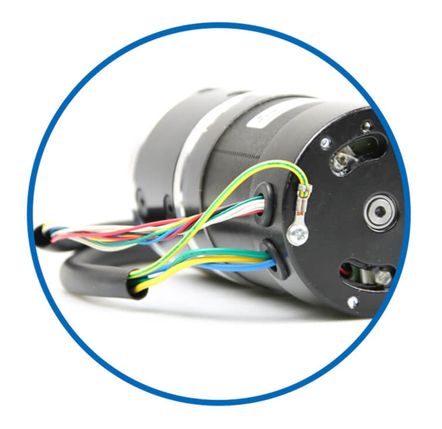
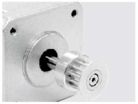
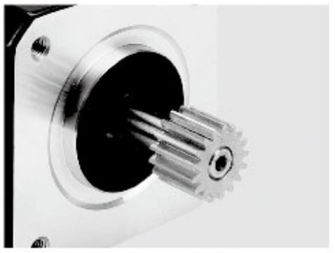
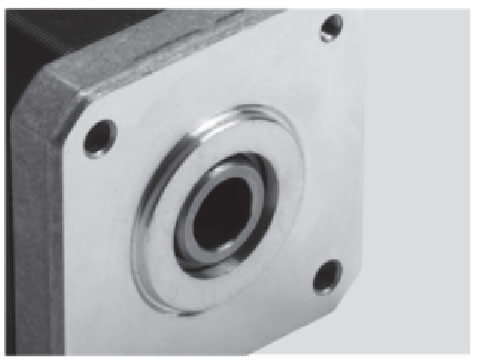
| Wires | Covers | Fans | Shafts | Integrated Drivers |
![bldc motor supplier]() | ![bldc motor supplier]() | ![bldc motor supplier]() | ![bldc motor supplier]() | ![bldc motor supplier]() |
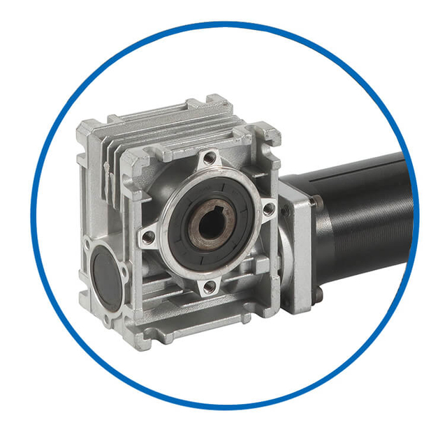
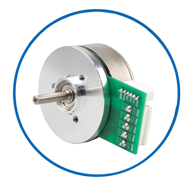
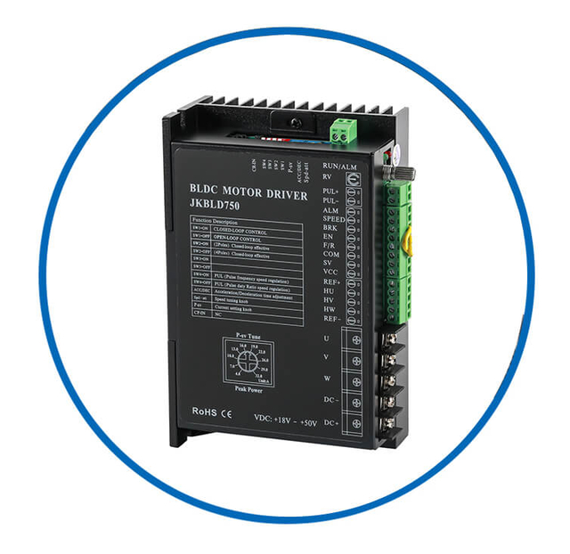
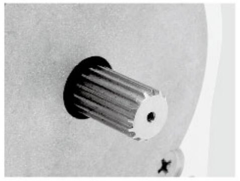
| Brakes | Gearboxes | Out Rotors | Coreless Dc | Drivers |
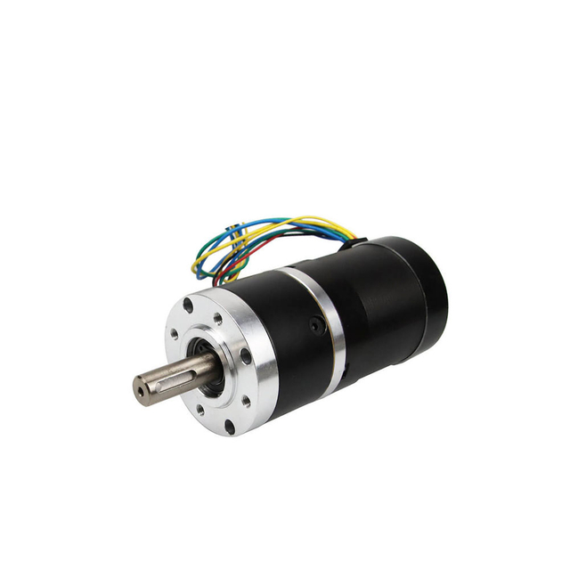
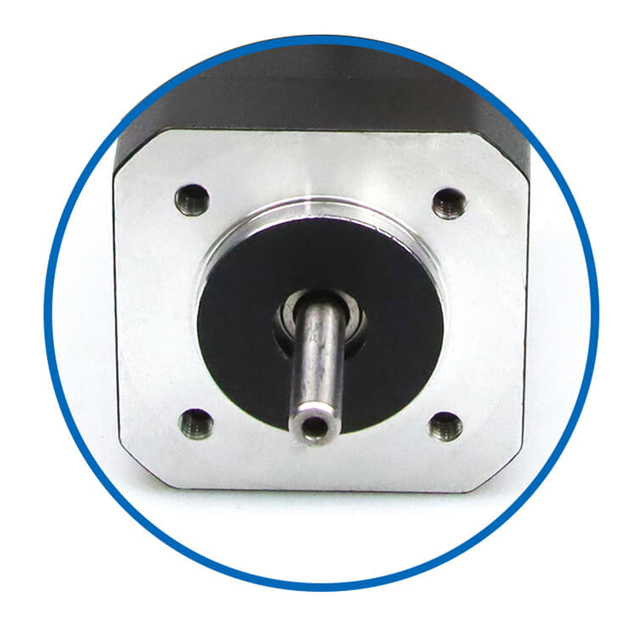
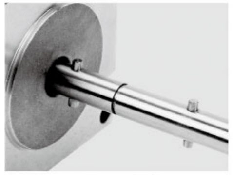
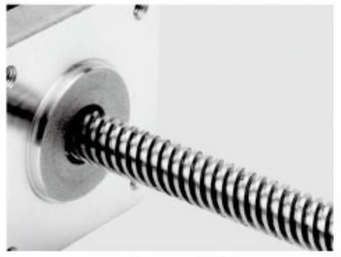
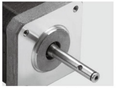
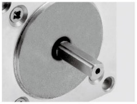
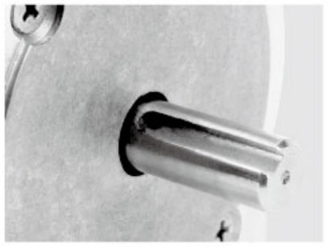
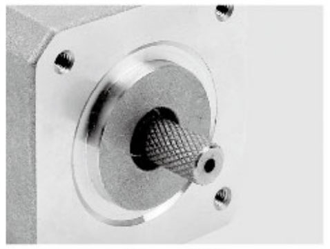
Motor Shaft Customized Service
Jkongmotor offer many different shaft options for your motor as well as customizable shaft lengths to make the motor fit your application seamlessly.
1. BLDC Motor Types Based on Back-EMF Waveform
1.1 Trapezoidal BLDC Motor
Trapezoidal BLDC motors generate a trapezoidal back-EMF waveform and typically use six-step (120°) electronic commutation.
Key characteristics:
Typical applications:
Electric vehicles
Pumps and fans
Power tools
Compressors
1.2 Sinusoidal BLDC Motor (PMSM)
These motors produce a sinusoidal back-EMF waveform and are often referred to as Permanent Magnet Synchronous Motors (PMSM).
Key characteristics:
Typical applications:
Robotics
CNC machines
Servo systems
Medical equipment
2. BLDC Motor Types Based on Rotor Structure
In inner rotor designs, the rotor is positioned inside the stator.
Key characteristics:
High speed capability
Compact size
Good heat dissipation
Low rotor inertia
Typical applications:
Drones
Spindles
Cooling fans
Precision drives
In outer rotor motors, the rotor surrounds the stator.
Key characteristics:
Typical applications:
Electric bicycles
Hub motors
Gimbals
Direct-drive systems
3. BLDC Motor Types Based on Stator Design
3.1 Slotted BLDC Motor
Slotted stators use iron cores with slots to house the windings.
Key characteristics:
High torque density
Strong magnetic coupling
Higher cogging torque
Typical applications:
Industrial drives
Electric vehicles
Heavy-duty machinery
Slotless BLDC motors eliminate stator slots.
Key characteristics:
Typical applications:
4. BLDC Motor Types Based on Mechanical Construction
4.1 Inrunner BLDC Motor
Inrunners are a form of inner rotor motor optimized for high speed and low torque.
Typical applications:
RC vehicles
Drones
Spindle drives
4.2 Outrunner BLDC Motor
Outrunners are optimized for high torque at low speed.
Typical applications:
UAV propulsion
Electric bicycles
Direct-drive systems
5. BLDC Motor Types Based on Control Method
Sensored BLDC motors use Hall sensors or encoders.
Key characteristics:
Typical applications:
Robotics
Conveyors
Servo drives
5.2 Sensorless BLDC Motor
Sensorless BLDC motors rely on back-EMF detection.
Key characteristics:
Typical applications:
Fans
Pumps
HVAC systems
Appliances
6. BLDC Motor Types Based on Application Integration
A BLDC servo motor combines a BLDC motor with closed-loop control and feedback devices.
Key characteristics:
Typical applications:
Integrated BLDC motors include the driver, controller, and sometimes feedback in one compact unit.
Key characteristics:
Simplified installation
Reduced wiring
High system reliability
Typical applications:
Mobile robots
AGVs
Smart automation systems
Comparison Summary of BLDC Motor Types
| Classification | Key Advantage | Typical Use |
| Trapezoidal BLDC | Simple control | EVs, pumps |
| Sinusoidal BLDC | Smooth torque | Robotics, CNC |
| Inner Rotor | High speed | Drones, spindles |
| Outer Rotor | High torque | Hub motors |
| Slotted | High torque density | Industrial drives |
| Slotless | Smooth motion | Medical devices |
| Sensored | Low-speed accuracy | Servo systems |
| Sensorless | Low cost | HVAC, fans |
Conclusion
Understanding BLDC motor types is essential for selecting the optimal motor architecture for a given application. By evaluating back-EMF waveform, rotor structure, stator design, and control method, engineers can achieve the best balance of efficiency, torque, speed, noise, and reliability. Proper BLDC motor selection ensures superior performance, reduced energy consumption, and long-term operational stability across a wide range of industries.
You have not enough Humanizer words left. Upgrade your Surfer plan.
Back Electromotive Force (BEMF) voltage in a Brushless DC (BLDC) motor is the voltage generated in the motor windings when the rotor is rotating. It is an inherent electromagnetic phenomenon that directly reflects rotor speed, magnetic field strength, and motor design, and it plays a critical role in motor control, speed regulation, and sensorless commutation.
Definition of BEMF Voltage
BEMF voltage is the induced voltage that opposes the applied supply voltage according to Lenz’s Law. As the permanent magnet rotor of a BLDC motor spins, it cuts through the stator windings’ magnetic field, inducing a voltage in each phase winding.
In simple terms, the faster the motor rotates, the higher the BEMF voltage.
Basic BEMF Voltage Equation
The BEMF voltage in a BLDC motor is given by:
E = Kₑ × ω
Where:
This linear relationship makes BEMF a reliable indicator of motor speed.
Physical Origin of BEMF in BLDC Motors
In BLDC motors:
The rotor contains permanent magnets
The stator contains fixed windings
Rotation causes a changing magnetic flux linkage
According to Faraday’s Law of Electromagnetic Induction, this changing flux induces a voltage in the stator windings, which appears as BEMF.
BEMF Waveforms in BLDC Motors
The shape of the BEMF voltage depends on motor design:
Trapezoidal BEMF
Common in traditional BLDC motors
Enables six-step (120°) commutation
Sinusoidal BEMF
Found in PMSM-type BLDC motors
Enables sinusoidal or vector control
The waveform directly influences control strategy, torque ripple, and efficiency.
Role of BEMF in Sensorless Control
The role of Back Electromotive Force (BEMF) in sensorless motor control is fundamental to achieving accurate commutation, speed estimation, and stable operation without mechanical position sensors. In Brushless DC (BLDC) motors and Permanent Magnet Synchronous Motors (PMSM), BEMF serves as the primary electrical signal used to infer rotor position and rotational speed, enabling cost-effective, compact, and reliable drive systems.
Principle of Sensorless Control Using BEMF
In sensorless control, the controller estimates rotor position by analyzing the voltage induced in the unenergized motor phase. As the rotor rotates, its magnetic field induces BEMF in the stator windings. This voltage contains precise information about the rotor’s angular position relative to the stator.
By continuously monitoring BEMF behavior, the controller determines when to switch phase currents, replacing the function of Hall sensors or encoders.
BEMF Zero-Crossing Detection
The most common sensorless BLDC control method is BEMF zero-crossing detection.
Key steps include:
One phase is left floating during commutation
BEMF voltage in that phase is measured
The zero-crossing point indicates rotor alignment
A calculated time delay triggers the next commutation event
This technique enables accurate 120-degree electrical commutation in trapezoidal BLDC motors.
BEMF-Based Rotor Position Estimation
BEMF voltage varies with rotor position according to:
E = Kₑ × ω × f(θ)
Where:
By analyzing BEMF phase relationships, the controller reconstructs rotor position without direct measurement.
Speed Estimation Using BEMF
Since BEMF amplitude is directly proportional to rotor speed:
Controllers use BEMF magnitude to estimate speed, enabling:
Closed-loop speed regulation
Load disturbance compensation
Stable steady-state operation
Advantages of BEMF-Based Sensorless Control
Using BEMF for sensorless control provides multiple engineering benefits:
Eliminates mechanical sensors, reducing cost and size
Improves system reliability by removing failure-prone components
Enhances thermal robustness
Simplifies wiring and installation
Enables operation in harsh environments
Limitations of BEMF Sensorless Control
Despite its advantages, BEMF-based sensorless control has limitations:
Ineffective at very low or zero speed
Requires minimum rotational speed to generate measurable BEMF
Sensitive to electrical noise and voltage distortion
More complex filtering and signal processing needed
These limitations often require hybrid startup strategies.
Startup Techniques in Sensorless Control
Since BEMF is negligible at standstill, sensorless drives use:
Once sufficient speed is reached, control transitions smoothly to BEMF-based closed-loop operation.
BEMF in Sinusoidal and Vector Control Systems
In PMSM and sinusoidal BLDC systems, BEMF is used indirectly through:
Observers
Estimators
Phase-locked loops (PLL)
These techniques extract rotor position information from stator voltage and current models, extending sensorless control into lower-speed regions.
Impact of BEMF Accuracy on Torque Control
Accurate BEMF estimation ensures:
Incorrect BEMF interpretation leads to miscommutation, vibration, and power loss.
Applications of BEMF-Based Sensorless Control
BEMF sensorless control is widely used in:
Electric vehicles
HVAC systems
Pumps and fans
Power tools
Drones and UAVs
Industrial automation
These applications benefit from high efficiency, low cost, and reduced maintenance.
Conclusion
The role of BEMF in sensorless control is central to modern BLDC and PMSM drive systems. By leveraging naturally induced voltage in motor windings, sensorless control achieves accurate rotor position detection, reliable speed estimation, and efficient torque control without mechanical sensors. When properly implemented, BEMF-based sensorless control delivers high performance, robustness, and long-term reliability across a wide range of applications.
BEMF and Speed Regulation
BEMF voltage naturally increases with speed and acts as a self-regulating mechanism:
This behavior explains why BLDC motors have a defined no-load speed at a given supply voltage.
Relationship Between BEMF and Torque
BEMF is directly related to torque through motor constants:
Torque constant (Kₜ)
BEMF constant (Kₑ)
In SI units:
Kₜ = Kₑ
This equality allows precise torque estimation from electrical measurements, enabling advanced motor control techniques.
BEMF Voltage During Regenerative Operation
When a BLDC motor is driven mechanically faster than its electrical input would allow:
BEMF exceeds supply voltage
Current reverses direction
Motor operates as a generator
This principle is used in:
Factors Affecting BEMF Voltage
BEMF voltage is influenced by:
Understanding these factors is essential for accurate motor modeling and controller design.
Why BEMF Voltage Is Critical in BLDC Motors
Back Electromotive Force (BEMF) voltage is one of the most important electrical characteristics of a Brushless DC (BLDC) motor. It is not merely a byproduct of motor rotation; it is a core functional signal that governs commutation accuracy, speed regulation, torque control, efficiency, and overall system reliability. Understanding why BEMF voltage is critical is essential for designing, controlling, and optimizing BLDC motor-driven systems.
Foundation of Electronic Commutation
BLDC motors rely on electronic commutation rather than mechanical brushes. BEMF voltage provides the necessary information to determine rotor position relative to the stator.
Key roles include:
Identifying the correct phase switching sequence
Ensuring proper alignment of stator magnetic fields with rotor magnets
Preventing miscommutation and torque loss
Without accurate BEMF detection, stable motor operation is impossible.
Enabler of Sensorless Motor Control
BEMF voltage is the cornerstone of sensorless BLDC control.
Critical functions:
Rotor position estimation without Hall sensors
Zero-crossing detection for commutation timing
Reduced system cost and complexity
Sensorless operation improves reliability by eliminating mechanical sensors and wiring, making BEMF indispensable in many modern BLDC applications.
Direct Indicator of Motor Speed
BEMF voltage is directly proportional to rotor speed:
E ∝ ω
This relationship allows controllers to:
Estimate speed accurately
Regulate speed without external sensors
Detect overspeed and abnormal conditions
Speed control based on BEMF improves system stability and responsiveness.
Intrinsic Current Limiting Mechanism
As speed increases, BEMF voltage rises and opposes the supply voltage, naturally limiting current flow.
Engineering benefits include:
This self-regulating behavior enhances motor longevity and safety.
Essential for Torque Control and Efficiency
BEMF is directly linked to torque through the motor constants:
Torque constant (Kₜ)
BEMF constant (Kₑ)
Accurate BEMF modeling enables:
Efficient torque production relies heavily on accurate BEMF interpretation.
Influence on Torque Ripple and Noise
Incorrect commutation timing caused by poor BEMF detection results in:
Increased torque ripple
Audible noise
Mechanical vibration
Precise BEMF sensing minimizes these effects, ensuring smooth and quiet operation.
Critical Role in Regenerative Braking
When a BLDC motor is driven faster than its electrical supply permits:
BEMF exceeds supply voltage
Current reverses direction
Energy flows back to the power source
This principle enables regenerative braking and energy recovery, improving system efficiency.
Determines Motor Speed Limits
The maximum achievable speed of a BLDC motor is constrained by BEMF voltage.
At high speeds:
BEMF approaches supply voltage
Available voltage for current drops
Torque capability decreases
Understanding BEMF limits is essential for proper motor and drive selection.
Supports Fault Detection and Diagnostics
Abnormal BEMF patterns can indicate:
Monitoring BEMF enhances predictive maintenance and fault diagnostics.
Critical in High-Performance Applications
In applications such as:
Electric vehicles
Drones and UAVs
Industrial automation
Robotics
Precise BEMF control ensures high efficiency, fast response, and operational reliability.
Conclusion
BEMF voltage is critical in BLDC motors because it underpins electronic commutation, enables sensorless control, governs speed and torque behavior, and protects the motor from electrical and thermal stress. It transforms BLDC motors from simple electromechanical devices into intelligent, high-performance drive systems. Mastery of BEMF behavior is essential for achieving efficient, reliable, and optimized BLDC motor operation.
BEMF voltage in a BLDC motor is the internally generated voltage produced by rotor motion that opposes the applied supply voltage. It is directly proportional to speed and serves as a cornerstone for motor control, speed regulation, and sensorless operation. Mastery of BEMF behavior is essential for designing efficient, reliable, and high-performance BLDC motor systems.