Brushless DC motors (BLDC motors) are widely recognized for their high efficiency, compact size, long service life, and excellent controllability. However, in demanding industrial and automation applications, engineers often face a critical question: how can we extract more torque from a BLDC DC motor without sacrificing reliability or efficiency?
Maximizing torque in BLDC/DC motors requires a system-level strategy that balances electrical, magnetic, mechanical, and thermal factors. Key approaches include increasing controlled phase current, using advanced control methods like FOC and PWM, optimizing winding and magnetic circuit design, and implementing mechanical solutions such as gear reductions. From a product and factory customization standpoint, torque requirements directly influence motor frame selection, winding and magnet materials, driver electronics, and integrated modules (e.g., gearboxes, encoders). With professional design, advanced control tuning, and appropriate thermal management, manufacturers can tailor BLDC motor solutions to meet high-torque performance specifications for industrial, robotics, and automation applications.
In this comprehensive guide, we present a professional, engineering-focused approach to increasing BLDC motor torque. We examine electrical, magnetic, thermal, mechanical, and control-system strategies that enable higher torque output while maintaining stability, performance, and long-term durability.
Understanding Torque Production in BLDC DC Motors
Torque in a BLDC motor is fundamentally generated by the interaction between the stator magnetic field and the rotor magnetic field. The electromagnetic torque can be simplified as:
Torque ∝ Magnetic Flux × Phase Current
This means that increasing torque requires optimizing one or more of the following:
A successful torque-boosting strategy focuses on system-level optimization, not just one isolated change.
Jkongmotor ODM OEM Customized Bldc Motor Types
Bldc Motor Customized Service
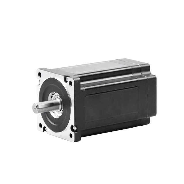
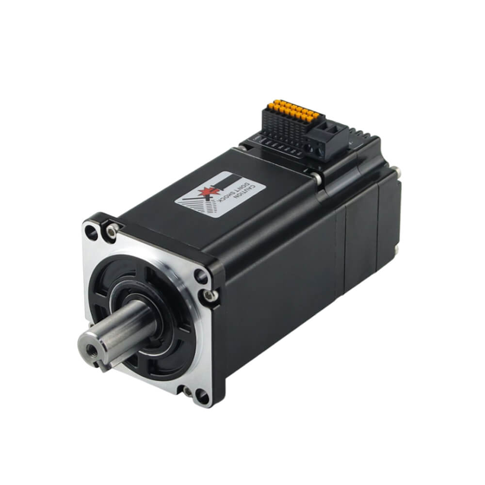
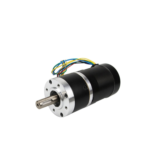
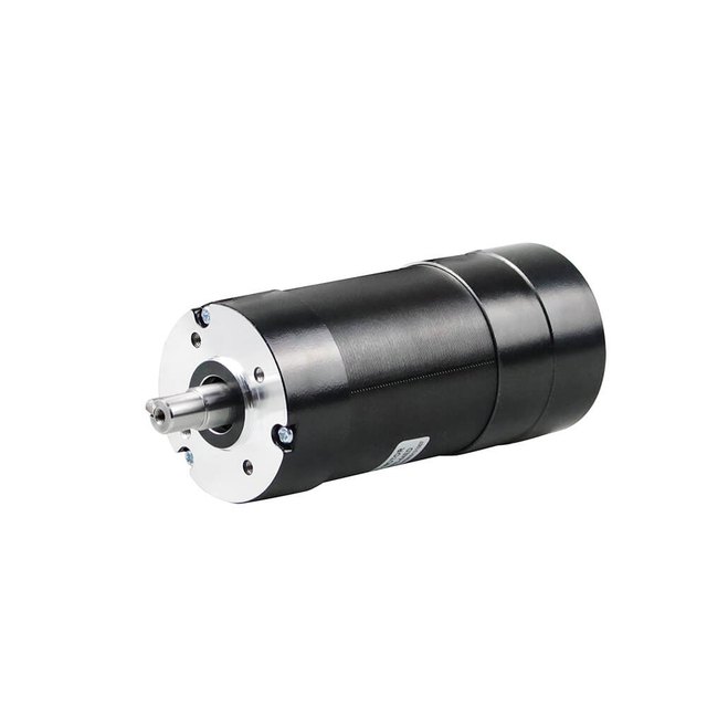
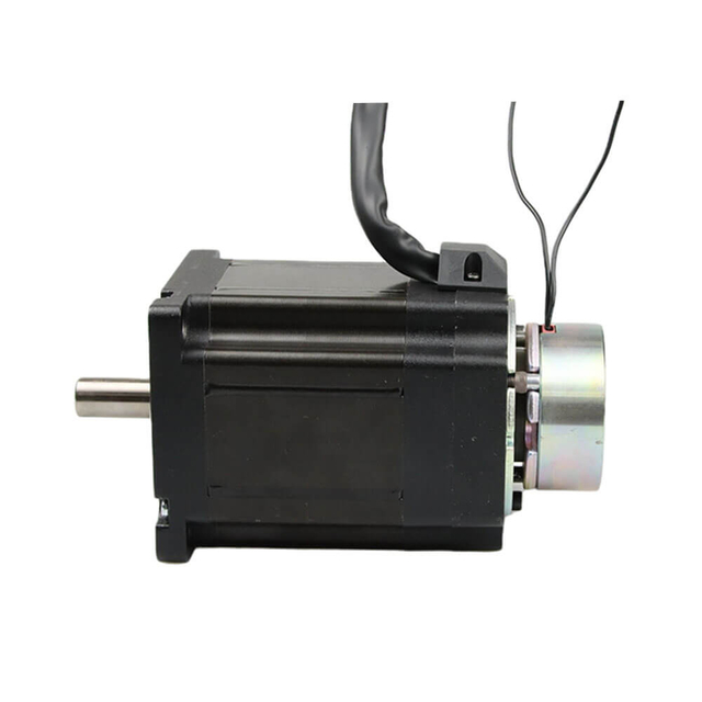
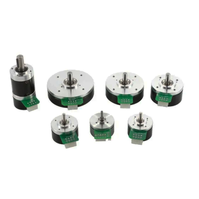
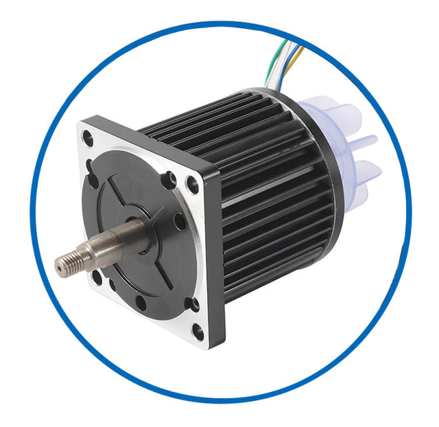
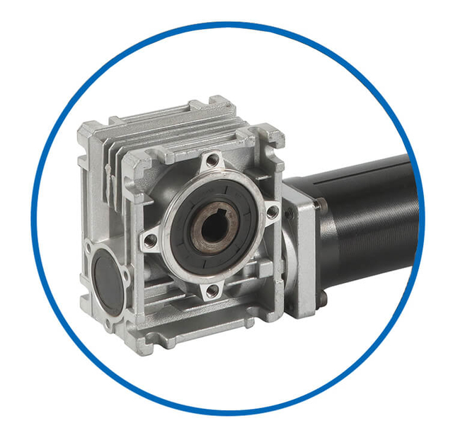
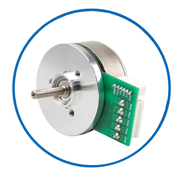
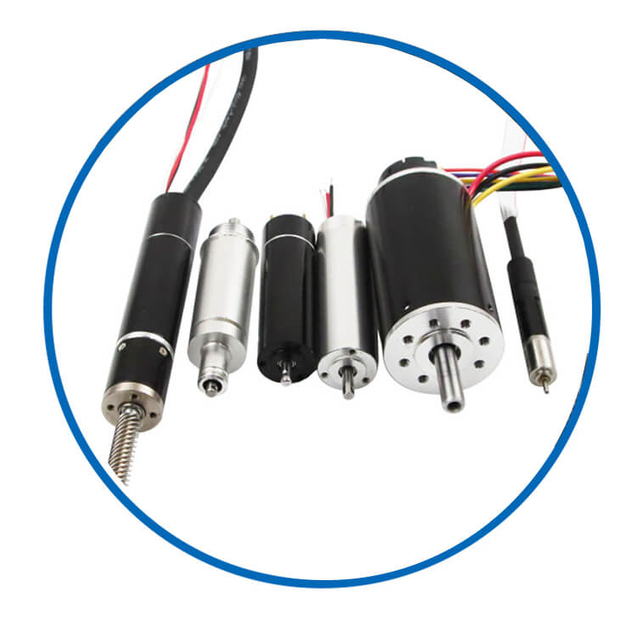
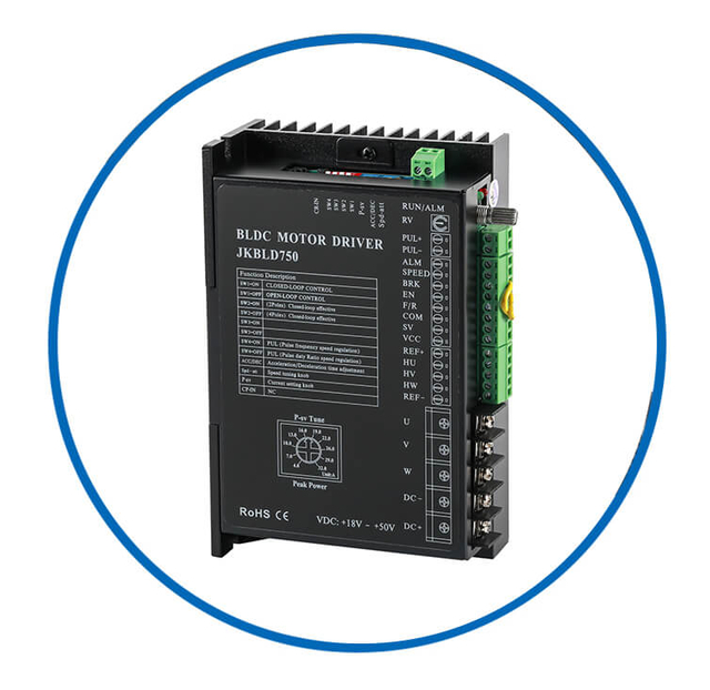
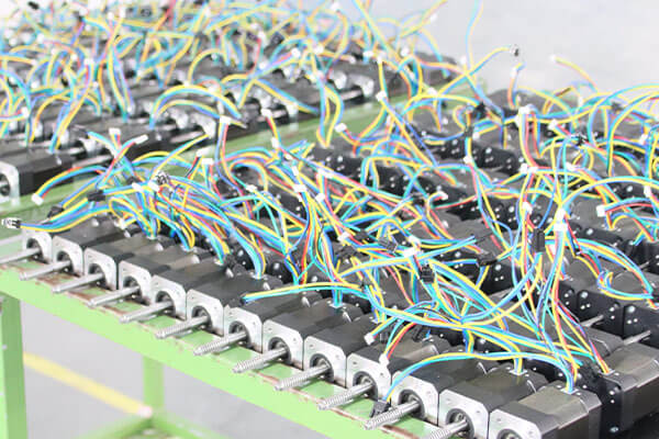
As a professional brushless dc motor manufacturer with 13 years in china, Jkongmotor offer various bldc motors with customized requirements, including 33 42 57 60 80 86 110 130mm, additionally, gearboxes, brakes, encoders, brushless motor drivers and integrated drivers are optional.
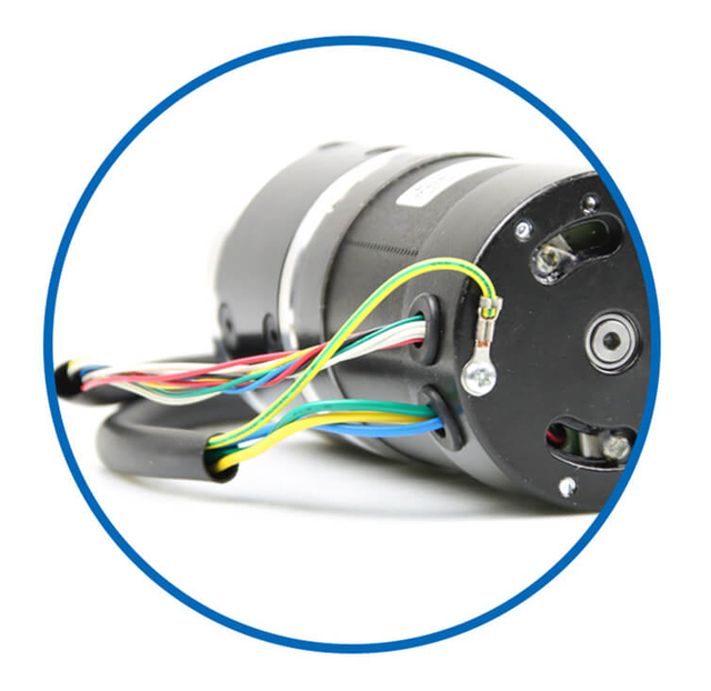
![bldc motor supplier]() | ![bldc motor supplier]() | ![bldc motor supplier]() | ![bldc motor supplier]() | ![bldc motor supplier]() | Professional custom brushless motor services safeguard your projects or equipment. No Brushes – Reduced Maintenance and Increased Lifespan High Efficiency and Low Power Loss High Torque-to-Weight Ratio Precise Speed and Position Control Quiet and Smooth Operation Wide Speed Range and Dynamic Performance Excellent Thermal Management Customizable Designs and Modular Configurations Multiple Control Methods Integration with Digital Interfaces and Sensors |
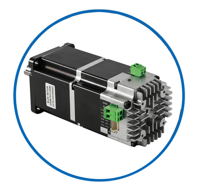
| Wires | Covers | Fans | Shafts | Integrated Drivers |
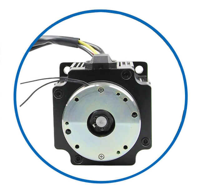
![bldc motor supplier]() | ![bldc motor supplier]() | ![bldc motor supplier]() | ![bldc motor supplier]() | ![bldc motor supplier]() |
| Brakes | Gearboxes | Out Rotors | Coreless Dc | Drivers |
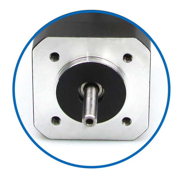
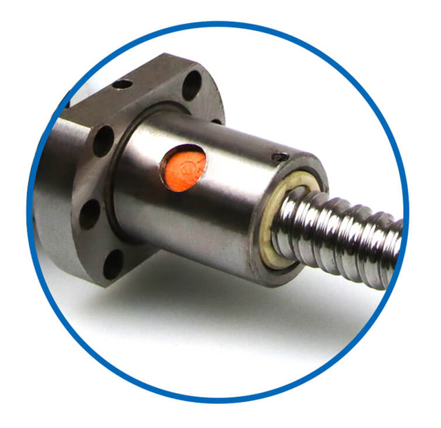
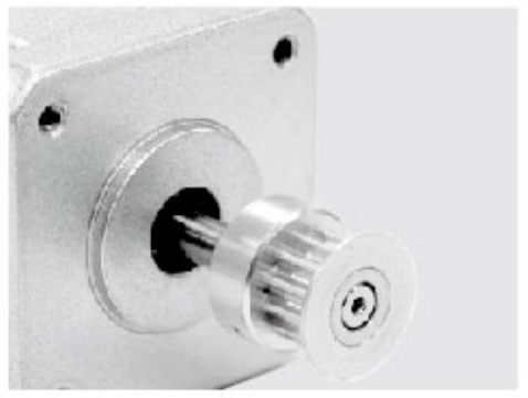
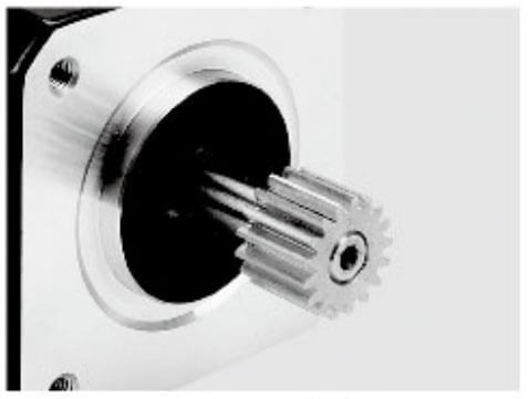
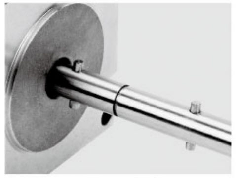
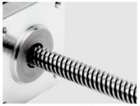
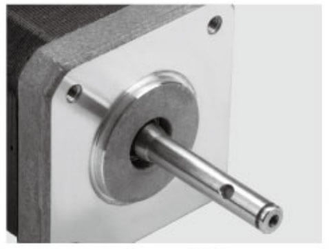
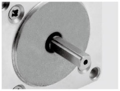
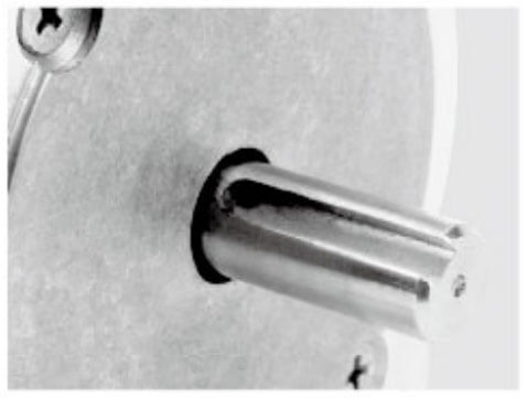
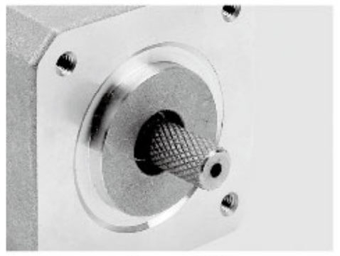
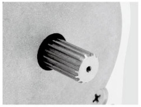
Motor Shaft Customized Service
Jkongmotor offer many different shaft options for your motor as well as customizable shaft lengths to make the motor fit your application seamlessly.
Increase Phase Current Safely and Effectively
The most direct way to increase torque is by increasing the phase current supplied to the BLDC motor.
Key technical methods include:
Using a higher-current-rated motor driver
Implementing low-resistance windings
Optimizing PWM switching and current loops
Reducing conduction and switching losses
However, higher current inevitably produces greater copper losses (I⊃2;R) and heat. Therefore, torque gains through current increase must be paired with advanced thermal design and precise current regulation.
Best practices
Deploy FOC (Field-Oriented Control) with real-time current feedback
Use high-resolution current sensors for accurate torque control
Apply dynamic current limiting to prevent thermal overload
When properly controlled, higher current allows the motor to deliver significantly greater continuous and peak torque.
Enhance Magnetic Flux Density
Torque can also be increased by strengthening the magnetic interaction inside the motor.
High-impact strategies include:
Upgrading to high-energy rare-earth magnets such as NdFeB
Optimizing air-gap geometry
Using high-permeability electrical steel laminations
Improving stator tooth and slot design
A stronger magnetic field increases the torque constant (Kt), allowing more torque per ampere.
Engineering advantages
Higher torque without excessive current
Improved low-speed torque stability
Increased efficiency at rated load
This approach is especially valuable for applications requiring high continuous torque rather than only short-term peaks.
Optimize Winding Design for Maximum Torque
The winding system is the electromagnetic heart of a BLDC motor. While magnets and control algorithms are critical, it is the stator winding design that ultimately determines how effectively electrical energy is converted into mechanical torque. By professionally optimizing winding parameters, manufacturers and system engineers can dramatically increase torque density, thermal efficiency, and continuous torque capability without enlarging the motor frame.
Below is a detailed, industry-level explanation of how winding design is optimized to achieve maximum torque output from a BLDC motor.
Increase the Torque Constant Through Turn Optimization
The torque constant (Kt) directly links motor current to torque output. Increasing the number of turns per phase raises the magnetic field generated by the stator, thereby increasing torque per ampere.
Professional turn optimization focuses on:
Selecting the ideal number of turns to balance torque, speed, and voltage
Matching winding turns to the available DC bus voltage
Avoiding excessive turns that cause high resistance and reduced efficiency
A properly optimized turn count allows the motor to produce higher torque at lower current, reducing copper loss and improving continuous-duty performance.
Maximize Slot Fill Factor
Slot fill factor refers to how much of the stator slot area is actually occupied by copper. A higher fill factor means lower resistance, stronger magnetic fields, and better heat conduction.
High-torque winding strategies include:
Rectangular or formed copper wire
Multi-strand parallel conductors
Precision automated winding
Vacuum pressure impregnation (VPI)
Improving fill factor directly increases current capability, enabling higher torque without overheating.
Select Optimal Conductor Size and Configuration
Conductor choice strongly affects both torque capability and efficiency.
Key professional approaches:
Thicker conductors to reduce resistive losses
Parallel winding paths to distribute current
Litz wire to minimize AC and skin-effect losses
Shorter end turns to reduce inactive copper length
Lower resistance means higher allowable current, and higher current means greater electromagnetic torque.
Choose the Most Effective Winding Topology
Winding topology controls how magnetic flux is distributed.
Common high-torque configurations include:
Concentrated windings – high torque density, compact design, strong low-speed torque
Distributed windings – smoother torque, lower cogging, improved high-speed behavior
Fractional-slot windings – reduced torque ripple, better efficiency, quieter operation
Selecting the correct topology improves flux utilization, torque smoothness, and saturation limits, all of which directly influence usable torque.
Enhance Magnetic Coupling and Flux Utilization
The purpose of windings is to generate magnetic fields that efficiently interact with the rotor magnets.
Optimization methods include:
Aligning winding distribution to the magnet pole geometry
Reducing leakage flux paths
Improving slot opening design
Matching winding pitch to back-EMF profile
These refinements strengthen the electromagnetic interaction, producing higher torque for the same electrical input.
Improve Thermal Performance Through Winding Engineering
Torque is often thermally limited. Advanced winding design significantly improves heat dissipation.
Professional techniques include:
High thermal conductivity insulation
Direct slot-to-housing heat paths
Resin impregnation to eliminate air gaps
Embedded temperature sensors
Better cooling allows higher continuous current, which directly enables higher continuous torque ratings.
Reduce Losses That Steal Torque
Not all electrical energy becomes torque. Some is lost as heat or stray magnetic fields.
Winding optimization reduces:
Reducing losses increases effective torque production and improves overall motor efficiency.
Enable High Peak Torque Capability
High-performance winding systems are designed to withstand short-term overload.
This includes:
High-temperature enamel insulation
Reinforced slot liners
Mechanically supported coils
Surge-resistant winding structures
Such designs allow safe peak current injection, delivering very high transient torque without damaging the motor.
Integrate Winding Design with Control Strategy
The most effective winding systems are developed in parallel with motor control algorithms.
Optimized windings support:
Field-Oriented Control (FOC)
Maximum Torque Per Ampere (MTPA)
Low-speed high-torque operation
Reduced torque ripple
This system-level integration ensures that the winding design is fully exploited, producing the maximum practical torque output.
Conclusion
Optimizing winding design is one of the most powerful and cost-effective methods of increasing BLDC motor torque. Through precise control of turn count, conductor size, slot fill factor, topology, magnetic coupling, and thermal performance, engineers unlock higher torque density, greater overload capability, and longer continuous operation.
When winding design is treated not as a manufacturing detail but as a core electromagnetic system, BLDC motors achieve significantly higher torque, superior efficiency, and greater industrial reliability.
Apply Advanced Motor Control Algorithms
Maximizing torque output from a BLDC motor is not solely a matter of hardware; control algorithms play a decisive role. Advanced motor control enables precise management of current, voltage, and rotor position, allowing the motor to deliver higher torque, smoother performance, and greater efficiency. By applying sophisticated control strategies, engineers can extract maximum usable torque while protecting the motor from overheating or overcurrent conditions.
Below is a professional, detailed explanation of how advanced motor control algorithms enhance torque performance in BLDC systems.
Field-Oriented Control (FOC)
Field-Oriented Control is the industry-standard approach for high-performance torque regulation. FOC separates the motor current into two orthogonal components:
By controlling Iq independently, FOC ensures that all available current contributes to torque production, maximizing efficiency and torque output.
Benefits include:
Maximum Torque Per Ampere (MTPA) operation
Smooth low-speed torque with minimal ripple
High dynamic response for acceleration and deceleration
Reduced energy losses compared to simpler scalar control
FOC allows motors to achieve peak torque and continuous torque without overstressing the windings, making it ideal for robotics, automation, and precision machinery.
Direct Torque Control (DTC)
Direct Torque Control is another high-performance algorithm, particularly effective in applications requiring ultra-fast torque response.
Key features:
Torque and flux are directly controlled without intermediate transformations
Rapid response to load changes and disturbances
Eliminates the need for pulse-width modulation in some implementations
DTC enables instantaneous torque adjustments, which is crucial for high-speed, high-inertia applications such as CNC machines or electric vehicle drivetrains.
Sensor-Based vs. Sensorless Control
Motor control algorithms can use either position sensors or operate sensorless:
Choosing the correct method ensures the motor delivers consistent torque under all operating conditions.
Maximum Torque per Ampere (MTPA) Strategies
MTPA algorithms optimize the ratio of current to torque output, ensuring every amp contributes maximally to torque.
Advantages include:
Reduced copper losses (I⊃2;R)
Improved continuous torque capacity
Lower heat generation
Higher overall efficiency
MTPA is especially critical in battery-powered systems, where current efficiency directly affects runtime and system longevity.
Torque Ripple Minimization
Advanced control algorithms reduce torque ripple, improving both precision and effective torque output.
Methods include:
Current waveform shaping
PWM modulation refinement
Compensation for cogging torque
Rotor position feedback integration
Minimizing ripple allows the motor to deliver smooth, continuous torque even under variable load, which is critical in robotics, conveyor systems, and medical devices.
Adaptive and Predictive Control
Next-generation control systems integrate adaptive algorithms that respond to changes in load, temperature, or power supply conditions:
Automatically adjust current limits to maintain torque
Compensate for thermal derating in real time
Predict load fluctuations and preemptively optimize torque output
Adaptive control ensures that the motor maintains maximum safe torque across all operating conditions, improving both performance and durability.
Integration with Thermal and Electrical Protection
Advanced algorithms work hand-in-hand with protection systems:
Thermal sensors feed real-time data into torque-limiting logic
Overcurrent and voltage monitoring prevent motor damage
Torque is adjusted dynamically to avoid overheating
This integration allows higher torque operation safely, extending motor life and reducing maintenance.
Applications Benefiting from Advanced Motor Control
Advanced torque-focused control is essential in:
Industrial robots and cobots – for smooth, precise motion under variable loads
Automated guided vehicles (AGVs) – for high torque during acceleration or ramp climbing
CNC machines and machine tools – for maintaining consistent torque under cutting loads
Electric actuators and aerospace applications – for reliable torque under extreme conditions
In these environments, control algorithms directly unlock torque that would otherwise remain unattainable with hardware adjustments alone.
Conclusion
Applying advanced motor control algorithms is critical for extracting maximum torque from a BLDC motor. Techniques such as Field-Oriented Control, Direct Torque Control, MTPA optimization, torque ripple minimization, and adaptive control allow precise, efficient, and reliable torque delivery. When paired with optimized motor design, thermal management, and system-level integration, advanced control transforms theoretical torque into usable mechanical power, meeting the most demanding industrial and precision applications.
Improve Thermal Management to Unlock Higher Continuous Torque
In BLDC motor systems, continuous torque is almost always thermally limited. While electromagnetic design determines how much torque a motor can produce, thermal management determines how much torque it can sustain. Without effective heat dissipation, higher current rapidly elevates winding and magnet temperature, forcing derating and reducing reliability. By professionally engineering the thermal path, we unlock higher continuous torque, longer duty cycles, and improved system stability.
Below is a detailed, industry-level explanation of how thermal management directly enables higher continuous torque in BLDC motors.
Understand the Thermal–Torque Relationship
Torque in a BLDC motor is proportional to current, and current generates heat. The primary heat sources are:
Copper losses (I⊃2;R) in windings
Core losses in laminations
Switching and conduction losses in the drive electronics
If this heat is not removed efficiently, temperature rises cause:
Increased winding resistance
Reduced magnetic strength
Insulation degradation
Premature bearing and lubricant failure
Effective thermal management allows higher permissible current, which directly enables higher continuous torque output.
Create an Efficient Heat Conduction Path
The most critical principle in motor cooling is minimizing thermal resistance from the heat source to the ambient environment.
Professional motor designs emphasize:
Direct thermal paths from winding to stator core
High-conductivity slot liners and potting compounds
Tight lamination stacking with low interface resistance
Thermally optimized end-turn support structures
By improving conduction, internal heat reaches the housing faster, lowering winding temperature and supporting sustained high-torque operation.
Use High-Thermal-Conductivity Materials
Material selection strongly influences torque capability.
High-performance thermal materials include:
Aluminum or magnesium housings
Copper-rich stator cores
Thermally conductive epoxies and varnishes
Ceramic-filled insulation coatings
These materials spread heat efficiently, reducing hot spots and allowing higher continuous current density.
Enhance Winding Heat Transfer
The windings are the dominant heat source. Their thermal treatment is decisive.
Key professional practices:
Vacuum pressure impregnation (VPI) to eliminate insulating air gaps
Resin bonding of coils to stator teeth
Flattened or rectangular conductors for higher surface contact
Direct slot cooling techniques
Improved winding-to-core heat transfer dramatically raises the allowable thermal load, directly increasing continuous torque rating.
Optimize Motor Housing and External Cooling
The motor housing is the main heat exchanger.
High-torque thermal designs often incorporate:
Finned housings for increased surface area
Integrated heat sinks
Forced-air cooling channels
Sealed liquid-cooling jackets
In high-duty applications, liquid cooling can multiply the continuous torque capability by allowing several times higher heat rejection compared to natural convection.
Implement Active Cooling Technologies
When passive cooling reaches its limit, active systems unlock new torque ranges.
These include:
Active cooling stabilizes internal temperature under high current, enabling constant high-torque output without thermal cycling.
Protect Magnets to Preserve Torque
Permanent magnets are temperature sensitive. Excess heat reduces magnetic flux and therefore torque.
Thermal protection strategies include:
Magnet isolation barriers
Dedicated rotor cooling paths
Low-loss magnet grades
Thermal shields between stator and rotor
By maintaining magnet temperature, the motor preserves its torque constant, efficiency, and long-term stability.
Integrate Real-Time Thermal Monitoring
High-torque systems depend on intelligent temperature control.
Professional solutions incorporate:
Embedded winding temperature sensors
Housing and bearing thermal probes
Real-time thermal modeling in the drive
Adaptive current derating algorithms
These systems maximize usable torque by operating safely at the highest permissible thermal boundary.
Reduce Losses to Lower Thermal Load
Thermal management is not only about removing heat, but also about generating less of it.
Optimization includes:
Lower losses directly increase the proportion of electrical power converted into useful mechanical torque.
Enable Higher Continuous Torque Through System Integration
The highest continuous torque systems are never the result of cooling alone. They combine:
Optimized electromagnetic design
Advanced winding engineering
High-efficiency power electronics
Integrated cooling architecture
When thermal design is treated as a core performance parameter, BLDC motors move from intermittent high torque to true continuous high-torque operation.
Conclusion
Improving thermal management is the most effective way to unlock higher continuous torque from a BLDC motor. By reducing thermal resistance, enhancing heat transfer, implementing active cooling, and integrating real-time monitoring, we raise the allowable current ceiling. The result is greater sustained torque, improved reliability, longer service life, and superior industrial performance.
Increase Torque Through Gear Reduction
When a BLDC motor’s native torque is insufficient for a specific application, one of the most reliable methods to boost output is mechanical torque multiplication through gear reduction. Gear systems allow a motor to maintain its speed characteristics while delivering significantly higher torque to the load. Properly designed gear reduction not only increases torque but also improves precision, efficiency, and overall system performance.
Below is a professional, detailed explanation of how gear reduction enhances BLDC motor torque.
The Principle of Gear Reduction
Gear reduction increases torque by converting motor speed into mechanical advantage:
Torqueoutput=Torquemotor×Gear RatioTorque_{output} = Torque_{motor} \times Gear\ Ratio
Torqueoutput=Torquemotor×Gear Ratio
A higher gear ratio multiplies the torque at the output shaft proportionally while reducing the output speed. This is particularly effective when:
High load inertia requires low-speed, high-torque motion
Motors must operate within safe current and thermal limits
Precision motion is critical in automation or robotics
By shifting torque generation from the motor to the gear system, we can achieve greater mechanical output without oversizing the motor.
Types of Gear Systems for Torque Multiplication
Selecting the appropriate gear type is essential for efficiency, reliability, and torque performance.
Planetary Gearboxes
Compact and high-torque capability
Multiple gear stages provide ratios from 3:1 up to 100:1 or more
Excellent torque density and minimal backlash
Common in robotics, AGVs, and automation equipment
Harmonic Drives
Ultra-high precision with zero backlash
High gear ratios (up to 160:1) in compact form factors
Ideal for robotic joints, CNC rotary tables, and medical devices
Smooth torque transfer with minimal vibration
Cycloidal Drives
Extremely high torque capacity
High shock-load resistance
Durable under heavy industrial applications
Often used in packaging machines, presses, and lifting systems
Spur and Helical Gears
Efficient and robust
Lower cost for moderate torque multiplication
Suitable for conveyor drives, actuators, and light automation
Benefits of Gear Reduction for Torque Enhancement
Increased Torque Without Overloading the Motor
Gear reduction allows the motor to operate within its current limits, reducing thermal stress while delivering higher torque to the load.
Improved Load Control and Stability
Torque multiplication stabilizes motion under variable loads, essential for robotics and precision automation.
Enhanced Positioning Accuracy
Gearing reduces the effective rotational step per motor pulse, improving resolution and smoothness.
Optimized Motor Efficiency
By operating at higher speeds and lower currents, motors experience less copper and core loss, increasing system efficiency.
Design Considerations for Gear Reduction Systems
When integrating gear reduction, the following factors are critical:
Gear Ratio Selection: Balance torque multiplication with desired output speed. Excessive reduction may limit speed and increase system complexity.
Backlash Management: For high-precision applications, low or zero-backlash gears (harmonic or planetary) maintain accurate torque delivery.
Efficiency: Multi-stage reduction can introduce losses. Select high-quality gears to maintain torque efficiency above 90%.
Thermal Considerations: Gears may generate heat; proper lubrication and housing cooling extend life and maintain performance.
Mechanical Integration: Align shafts, bearings, and couplings to minimize torque loss due to misalignment or friction.
Applications Leveraging Gear Reduction for Torque
Gear reduction is widely used in industrial applications where high torque is essential, including:
Robotic arms – For lifting heavy payloads and precision motion
Automated guided vehicles (AGVs) – To climb ramps and transport loads
CNC machinery – For spindle torque multiplication and rotary tables
Packaging systems – To handle heavy or variable loads with smooth motion
Electric actuators – To increase thrust and torque in aerospace and defense applications
In all these systems, gear reduction allows smaller motors to deliver performance levels equivalent to much larger machines, improving compactness, efficiency, and cost-effectiveness.
Conclusion
Gear reduction is one of the most reliable and practical methods to increase torque in BLDC motor applications. By selecting the right gear type and ratio, integrating precision couplings, and maintaining high mechanical efficiency, engineers can multiply the motor’s torque output without overstressing the motor or compromising performance. Whether for industrial automation, robotics, or high-precision actuation, gear reduction transforms the torque capabilities of BLDC systems into real-world mechanical power.
Select a Motor with Higher Torque Density
When application torque demands exceed what optimization alone can deliver, the most effective solution is to select a motor with higher torque density. Torque density—defined as torque output per unit volume or weight—is a decisive performance metric in modern BLDC motor systems. A higher torque density motor provides more usable torque in the same or smaller physical package, enabling stronger performance, more compact machines, and higher system efficiency.
Below is a detailed, professional explanation of how and why selecting a higher torque density motor dramatically improves achievable torque.
Understand Torque Density as a Core Selection Parameter
Traditional motor selection often focuses on rated power and speed. However, for high-load and low-speed industrial applications, torque density is far more relevant.
High torque density motors offer:
Higher continuous and peak torque
Reduced system size and weight
Better dynamic response
Greater overload capability
Selecting a motor optimized for torque density ensures that the system starts with a strong electromagnetic foundation rather than relying on aggressive electrical or thermal overstressing.
Choose Motor Architectures Designed for High Torque
Certain BLDC motor structures inherently produce more torque.
Outer-rotor motors place the rotor magnets on the outside, increasing the effective radius of force. This longer lever arm directly increases torque.
Benefits include:
Higher torque at lower speed
Better heat dissipation
Higher inertia for smooth motion
Excellent compact drive solutions
High-Pole-Count Motors
Increasing the number of magnetic poles enhances flux interaction and raises torque capability, particularly at low speeds.
Advantages include:
Axial-Flux Motors
Axial-flux BLDC motors use a disc-shaped magnetic field geometry that delivers extremely high torque density.
They provide:
Evaluate Advanced Electromagnetic Designs
Modern high-torque motors integrate refined electromagnetic engineering.
Key design features include:
High-energy NdFeB or SmCo magnets
Segmented or skewed stators
Optimized air-gap geometry
High-permeability, low-loss laminations
These enhancements increase the motor’s torque constant, enabling more torque per ampere and higher sustainable load.
Select Motors with Optimized Winding Systems
High torque density motors use windings designed for maximum copper utilization and thermal performance.
Typical characteristics include:
These features support higher continuous current, translating directly into higher continuous torque capability.
Prioritize Motors with Superior Thermal Design
Torque density is inseparable from thermal efficiency.
High-performance motors include:
Aluminum or liquid-cooled housings
Integrated heat paths from winding to shell
Internal airflow or cooling channels
Advanced thermal interface materials
Better cooling allows higher electromagnetic loading, sustaining greater torque without overheating.
Sometimes, true torque density is achieved at the system level.
High-torque-density solutions often integrate:
Planetary gearboxes
Harmonic drives
Cycloidal reducers
A compact geared BLDC motor system can deliver multiples of the motor’s native torque while maintaining excellent efficiency and precision.
Match Torque Density to Application Requirements
Different industries prioritize torque density differently.
High torque density motors are critical in:
Robotics and collaborative automation
Electric actuators and servo presses
Medical imaging and surgical robotics
Aerospace and defense systems
AGVs and mobile platforms
Selecting the right torque-dense architecture ensures the motor can meet load, speed, duty cycle, and environmental requirements without oversizing.
Evaluate Continuous vs Peak Torque Density
Professional motor selection distinguishes between:
A well-selected motor provides both: high transient capability and strong thermal stability for sustained torque output.
Conclusion
Selecting a motor with higher torque density is the most direct and reliable way to achieve higher torque output. By choosing architectures such as outer-rotor, high-pole-count, or axial-flux BLDC motors, combined with advanced magnetic materials, optimized windings, and superior thermal systems, we dramatically increase usable torque while minimizing size and complexity.
High torque density is not merely a specification—it is a system enabler that determines the limits of industrial motion performance.
Minimize Mechanical and Electrical Losses
Torque improvements are not only about increasing generation but also about reducing losses.
Key optimization areas
Lower losses allow more of the supplied electrical energy to become usable mechanical torque.
Implement Peak Torque Strategies
Many applications require short bursts of very high torque.
Professional techniques
Short-term current boosting
Adaptive thermal monitoring
Real-time magnet protection
Smart derating algorithms
This allows BLDC motors to deliver exceptionally high peak torque while maintaining safe long-term operation.
System-Level Integration for Maximum Torque
Achieving maximum torque from a BLDC motor is rarely the result of a single modification. True high-torque performance emerges when the entire system is engineered as an integrated solution. This includes the motor, drive electronics, control algorithms, thermal management, and mechanical interface. System-level integration ensures that each component works in harmony, unlocking peak performance, efficiency, and reliability.
Below is a detailed exploration of how system-level integration maximizes torque in BLDC applications.
Optimize Electromagnetic Design and Motor Selection
At the heart of torque generation is the motor itself. Selecting the right motor architecture is the first step in system integration:
High torque density designs (outer-rotor, axial-flux, high-pole-count)
High-energy magnets (NdFeB or SmCo) for stronger flux
Optimized windings with high slot fill factor and low resistance
Integrating these electromagnetic enhancements into the overall system allows higher torque per ampere and improves efficiency across all operating speeds.
Integrate Advanced Drive Electronics
The drive electronics must match the motor’s capabilities to achieve full torque potential:
Field-Oriented Control (FOC) to maintain maximum torque per ampere
High-current capable MOSFETs or IGBTs for efficient power delivery
Real-time current monitoring to safely handle torque peaks
PWM optimization to reduce switching losses and torque ripple
A harmonized motor and drive system ensures instantaneous torque response, critical for high-performance industrial and robotic applications.
Combine Control Algorithms with Thermal Management
System-level integration merges control strategy and heat management:
Adaptive current limiting based on real-time temperature
Maximum Torque per Ampere (MTPA) algorithms for efficiency
Thermal sensors embedded in windings, housing, and bearings
This coordination allows the motor to deliver higher continuous torque without risking overheating, extending both motor life and performance reliability.
Mechanical Integration and Load Matching
Torque is only useful if it is effectively delivered to the load. Mechanical integration focuses on:
Optimal gear reduction ratios to multiply motor torque
Low-backlash and high-stiffness couplings to minimize losses
Alignment of shaft, bearings, and load inertia to prevent torque drop
High-precision mounting to reduce vibration and cogging
Integrating the motor mechanically ensures that every bit of generated torque reaches the application efficiently, without energy loss or wear.
System-Level Thermal Design
Thermal integration extends beyond the motor:
Coordinated motor and inverter cooling systems
Heat path optimization from windings to housing to ambient environment
Use of forced-air, liquid, or hybrid cooling where appropriate
Thermal simulation during system design to identify hotspots
By managing heat at the system level, the motor can safely operate at higher currents, delivering maximum continuous torque.
Feedback and Sensing Integration
Accurate feedback is essential for torque control:
High-resolution encoders or resolvers for precise rotor position
Torque sensors or load cells for closed-loop torque control
Real-time monitoring of temperature, current, and voltage
Integrated sensing allows the control system to dynamically optimize torque output, prevent overstress, and improve motion accuracy.
Peak and Continuous Torque Coordination
System-level integration ensures both peak and continuous torque requirements are met:
Peak torque managed through short-term current boosting
Continuous torque maintained through thermal control and current limiting
Adaptive control allows the system to switch between modes without human intervention
This guarantees maximum performance without compromising safety, reliability, or motor longevity.
Applications of System-Level Torque Optimization
Integrated BLDC systems with coordinated motor, electronics, thermal, and mechanical design are essential in:
Industrial robots and cobots for precise, high-load movement
Automated Guided Vehicles (AGVs) for heavy payload transport
Medical devices requiring smooth, controlled high-torque motion
CNC machines and machine tools for cutting stability under load
Electric actuators in aerospace and defense systems
In all cases, the system-level approach enables torque levels that individual motor upgrades alone cannot achieve.
Conclusion
Maximum torque is not the result of isolated improvements—it is achieved when motor design, electronics, control algorithms, thermal management, mechanical integration, and feedback systems work together as a unified system. By engineering each component to complement the others, BLDC motors can deliver higher continuous torque, greater peak torque, and unmatched reliability in demanding industrial applications. System-level integration transforms high-torque motor potential into real-world performance.
Industrial Applications Demanding High BLDC Torque
High-torque BLDC (Brushless DC) motors have become a core technology across modern industry because they combine strong torque output, precise controllability, high efficiency, and long operational life. In environments where loads are heavy, motion must be accurate, and reliability is critical, high-torque BLDC systems deliver a decisive performance advantage. Below are the most important industrial sectors where high BLDC torque is not optional, but essential.
Robotics and Collaborative Automation
Industrial robots, collaborative robots (cobots), and autonomous robotic arms rely heavily on high-torque BLDC motors to achieve smooth, stable, and powerful joint movement. Each joint must generate enough torque to lift payloads, resist external forces, and accelerate rapidly without vibration.
High-torque BLDC motors enable:
High payload-to-weight ratios
Stable low-speed torque for precision tasks
Fast dynamic response for pick-and-place systems
Safe torque control for human–robot collaboration
In articulated robots, SCARA robots, and delta robots, torque density directly determines reach, payload capacity, and cycle time.
Automated Guided Vehicles (AGVs) and Mobile Robots (AMRs)
AGVs and AMRs operate in logistics centers, factories, and warehouses, transporting heavy materials continuously. These platforms demand high starting torque, high continuous torque, and excellent efficiency.
High-torque BLDC motors are used for:
They provide:
Strong stall and low-speed torque for ramp climbing
Smooth acceleration under heavy load
High battery efficiency for long operating cycles
Precise speed and torque control for navigation accuracy
Without high torque, AGVs cannot maintain performance under varying payloads.
CNC Machines and Precision Machine Tools
Machine tools depend on torque to achieve cutting stability, surface finish, and dimensional accuracy. High-torque BLDC motors are increasingly used in:
Spindle drives
Feed axes
Tool changers
Rotary tables
They provide:
Constant torque at low speed for tapping and milling
High peak torque for acceleration and deceleration
Rigid motion control to suppress chatter
Excellent thermal stability for long machining cycles
High torque ensures that cutting forces do not degrade precision or tool life.
Industrial Automation and Packaging Machinery
Packaging, labeling, bottling, and material-handling systems frequently operate under high inertia and frequent start-stop conditions. In these environments, BLDC motors must deliver rapid torque response and consistent force output.
High-torque BLDC motors are critical for:
Conveyors and indexing tables
Wrapping and sealing machines
Vertical form-fill-seal systems
Pick-and-place automation
They enable:
Stable movement of heavy products
Accurate tension and pressure control
High-speed operation without torque drop-off
Reduced mechanical wear through smooth motion profiles
Torque performance directly affects throughput, product quality, and uptime.
Medical and Laboratory Equipment
In medical and life-science systems, motors must deliver torque while maintaining ultra-smooth motion, low noise, and absolute reliability.
High-torque BLDC motors are widely used in:
Here, high torque allows:
Safe handling of heavy patient loads
Precise control of fluid and sample processing
Reliable long-term operation under continuous duty
Compact designs with high power density
High torque ensures performance without compromising patient safety or measurement accuracy.
Electric Actuators and Smart Motion Systems
Electric linear and rotary actuators increasingly replace hydraulic and pneumatic systems. To do so effectively, they require very high motor torque combined with fine position control.
High-torque BLDC motors drive:
They deliver:
Torque capacity directly determines actuator force output and system responsiveness.
Aerospace and Defense Systems
In aerospace and defense, torque is essential for systems exposed to high loads, extreme temperatures, and demanding duty cycles.
High-torque BLDC motors are used in:
They provide:
High torque-to-weight ratio
Reliable performance under shock and vibration
Precise torque vectoring and stabilization
Low maintenance operation in inaccessible locations
In these environments, torque is inseparable from mission reliability and system safety.
Renewable Energy and Heavy Industrial Equipment
Energy systems often operate with large inertia and high resistive loads, making torque a defining performance factor.
High-torque BLDC motors are applied in:
Wind turbine pitch control
Solar tracking systems
Industrial pumps and compressors
Automated mixing and processing equipment
They support:
Strong startup torque under load
Continuous high-torque operation
Precise torque modulation for process control
High efficiency to reduce operational cost
High torque ensures that energy systems remain stable, responsive, and productive.
Conclusion: Engineering Torque Beyond the Motor
Across robotics, automation, logistics, healthcare, aerospace, and energy systems, high BLDC torque is a foundational requirement. It determines how much a machine can lift, how accurately it can move, how fast it can respond, and how reliably it can operate. As industrial systems continue to demand higher power density, smarter control, and more compact designs, high-torque BLDC motors will remain a driving force behind next-generation industrial innovation.
Getting more torque from a BLDC DC motor is not about a single adjustment. It is about engineering synergy between electromagnetic design, power electronics, control intelligence, and thermal efficiency. By combining current optimization, magnetic enhancement, winding upgrades, advanced control, improved cooling, and mechanical leverage, we unlock a new performance class of BLDC motor systems.
High torque is achieved not by pushing limits blindly, but by designing intelligently.
FAQs of Fundamental BLDC/DC Motor Torque
1. What does torque mean in a BLDC/DC motor?
Torque is the rotational force the motor can produce, determined by magnetic flux and phase current.
2. How is torque generated in a BLDC motor?
Torque arises from the interaction between the stator’s magnetic field and the rotor’s permanent magnets.
3. What is the basic relationship between current and torque?
Torque is approximately proportional to the motor’s phase current multiplied by magnetic field strength.
4. What are the primary ways to increase torque in a BLDC motor?
By increasing phase current, enhancing magnetic flux, optimizing windings, and improving control strategies.
FAQs of Electrical & Control-Driven Torque Optimization
5. Can higher current drive more torque?
Yes — supplying higher phase current safely increases torque, but requires proper thermal and driver design.
6. Do advanced controllers help torque output?
Yes — Field-Oriented Control (FOC) and optimized PWM improve current utilization and torque precision.
7. Can firmware tuning affect torque performance?
Yes — customized firmware for current loops and torque limits can enhance output without hardware changes.
8. Is current sensing important for torque control?
Yes — real-time current feedback enables accurate torque regulation and safety limits.
FAQs of Magnetic & Mechanical Design
9. How does magnetic strength influence torque?
Stronger magnets or optimized magnetic circuits increase the torque constant, raising torque per amp.
10. Can upgrading magnets improve performance?
Yes — high-energy rare-earth magnets like NdFeB boost torque density and efficiency.
11. Does winding design matter for torque?
Absolutely — professional winding optimization enhances torque constant, thermal efficiency, and continuous torque.
12. How can gearboxes influence torque output?
Adding gear reduction multiplies mechanical torque at the output shaft without changing the motor frame.
FAQs of Thermal & Environmental Considerations
13. Why is thermal management critical for high torque?
Excess heat from higher currents can reduce magnetic performance and risk damage; cooling and thermal design are vital.
14. Can duty cycle affect torque capability?
Yes — operating within the rated duty cycle ensures consistent torque without overheating.
15. Does supply stability matter?
Stable voltage and current supply prevent torque fluctuation and maintain performance.
FAQs of Factory Customization & Product Variants
16. Can manufacturers customize torque specifications?
Yes — torque requirements influence winding design, magnet selection, frame size, and drive electronics for OEM/ODM projects.
17. What customization options support high torque?
Options include shaft modifications, integrated gearboxes, brakes, encoders, and tailored drive systems.
18. Does motor size affect torque?
Larger frames generally allow higher torque through bigger magnets, more windings, and greater current capacity.
19. Can custom mounting and mechanical parts improve torque delivery?
Yes — precision shaft, housing tolerances, and bearing choices reduce losses and support high torque loads.
20. Does JKongmotor offer integrated solutions for torque-critical applications?
Yes — integrated BLDC motors with optional drivers, brakes, and gearboxes support torque-focused system solutions.