In the field of automation and robotics, the linear actuator stepper motor has become a cornerstone of precision motion control. This innovative combination of rotary stepper motors and linear motion systems delivers highly accurate positioning, repeatability, and control across industries. From CNC machinery to 3D printers, medical devices, and robotic systems, linear actuator stepper motors drive modern innovation through precise linear displacement powered by digital command.
What Is a Linear Actuator Stepper Motor?
A linear actuator stepper motor is a type of motion control device that converts rotational motion from a stepper motor into linear motion using a lead screw, ball screw, or slider mechanism. Each pulse from the driver moves the motor shaft by a fixed increment, producing consistent and highly controlled linear movement.
Unlike traditional DC linear actuators, stepper-driven linear actuators do not require feedback sensors for position tracking. Their open-loop control system allows the actuator to move to exact positions based on digital pulses, making them ideal for applications requiring repeatability, fine control, and accuracy.

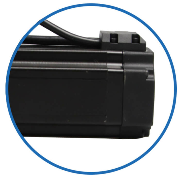
Integrated Linear Motions
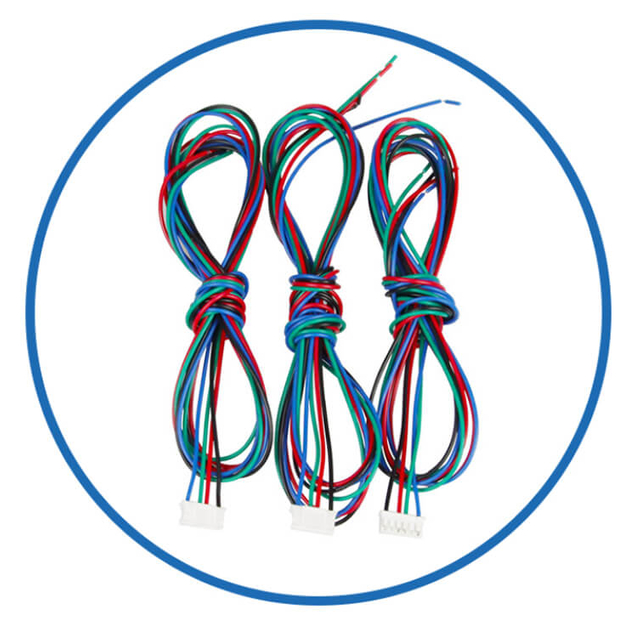
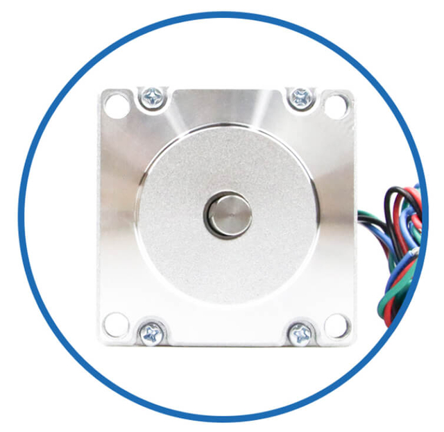
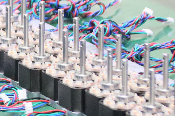
Motor Customized Service
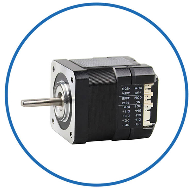
As a professional brushless dc motor manufacturer with 13 years in china, Jkongmotor offer various bldc motors with customized requirements, including 33 42 57 60 80 86 110 130mm, additionally, gearboxes, brakes, encoders, brushless motor drivers and integrated drivers are optional.
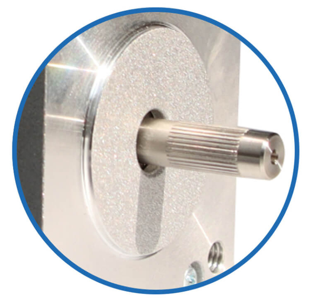
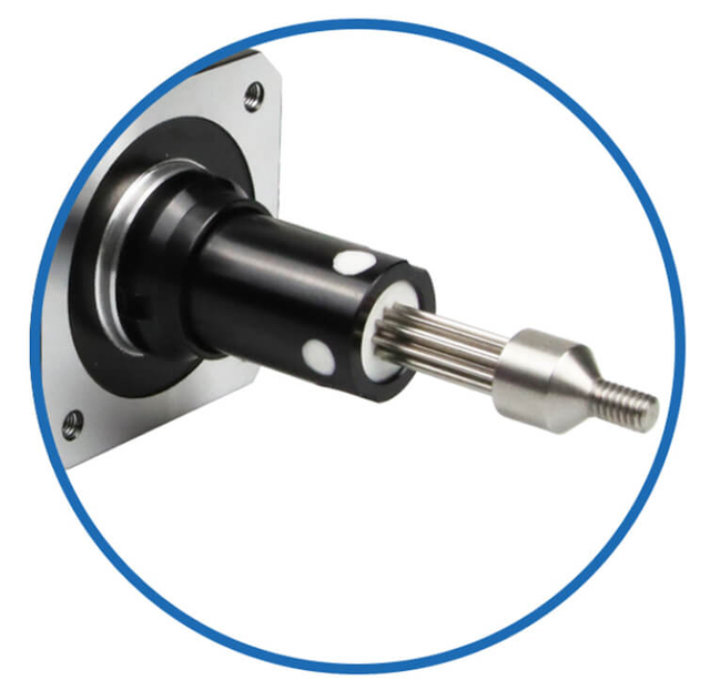
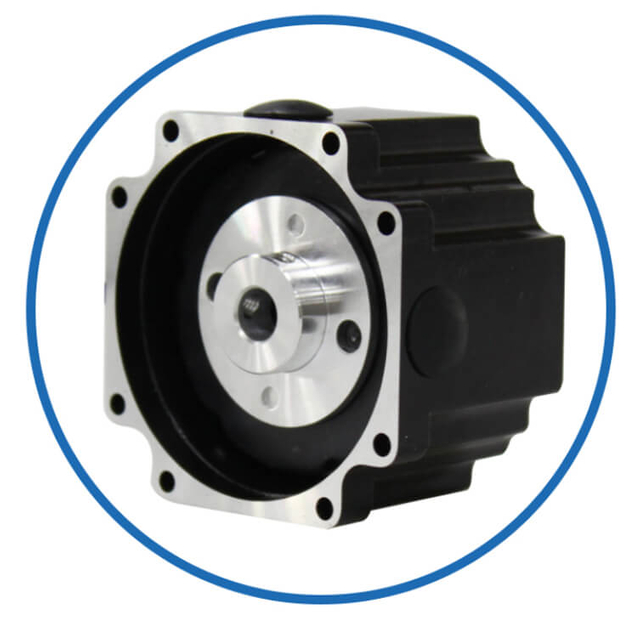
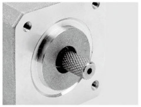
Motor Shaft Customized Service
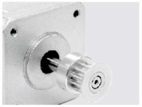
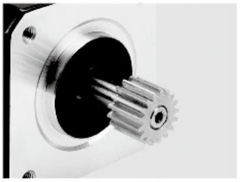
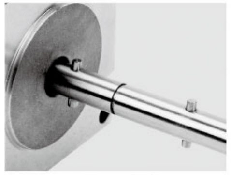
Jkongmotor offer many different shaft options for your motor as well as customizable shaft lengths to make the motor fit your application seamlessly.
Main Types of Linear Stepper Motors
Linear stepper motors are broadly classified into three main types based on their mechanical structure and motion conversion method:
External Linear Stepper Motors
Non-Captive Linear Stepper Motors
Captive Linear Stepper Motors
Let’s explore each type in detail.
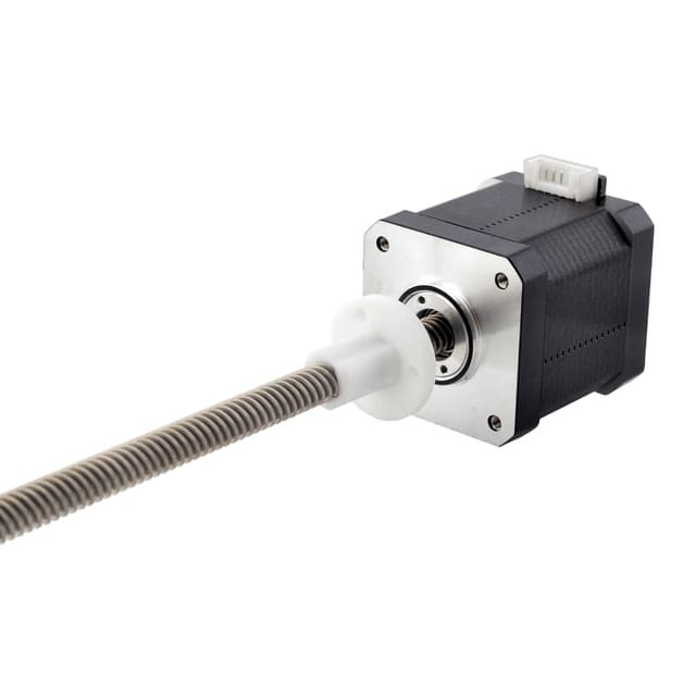
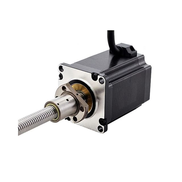
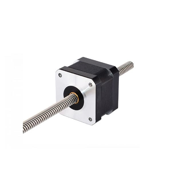
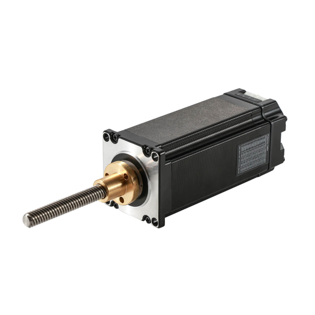
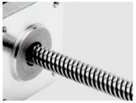
The external linear stepper motor is one of the most common and versatile configurations. In this design, the lead screw extends externally from the motor body, while the nut assembly is mounted separately on the load or moving part.
The T-type lead screw refers to the lead screw with a unique external thread configuration, typically used to convert rotary motion into linear motion. It is called "external" because the threads are located on the outside of the screw shaft, which improves load-bearing capacity and reduces backlash. The combination of a stepper motor and a lead screw system makes the External T-type Lead Screw Linear Stepper Motor an excellent choice for applications requiring high precision, reliability, and repeatability.
Key Features
Long travel range (limited only by screw length)
High thrust output
Simple integration with external systems
Excellent for push/pull applications
Advantages
Easy maintenance and replacement of the lead screw
Adaptable to various stroke lengths
Compatible with standard NEMA frame sizes (NEMA 11, 17, 23, etc.)
How It Works
When the motor rotates, the screw turns, and the nut travels linearly along its threads. The linear distance traveled per motor revolution depends on the lead screw pitch.
Typical Applications
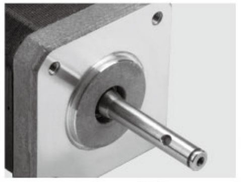
A non-captive linear stepper motor features a free-moving lead screw that passes through the motor body. The nut is attached to the rotor internally, converting rotation into linear motion, while the screw itself slides through as it moves.
A non-captive linear stepper motor is an electric motor that transforms electrical pulses into linear motion in discrete steps. Unlike captive linear stepper motors, which feature a fixed nut or mechanical component that prevents any movement of the nut off the lead screw, non-captive linear stepper motors utilize a floating nut. This design allows the nut to move freely along the lead screw as the motor operates.
Key Features
Compact, self-contained design
No need for external anti-rotation mechanisms
Allows both rotational and linear movement of the screw
Advantages
Ideal for limited-space environments
Lower mechanical complexity
Easy integration into compact assemblies
Excellent for small displacement or precision motion tasks
How It Works
Unlike the external type, the screw in a non-captive motor is not attached to the load. Instead, as the motor rotates, the nut inside the rotor moves along the screw threads, creating precise linear motion. The screw moves in and out of the motor housing as the load is driven.
Typical Applications
Medical and laboratory automation
Optical adjustment systems
Micropositioning equipment
Semiconductor wafer handling
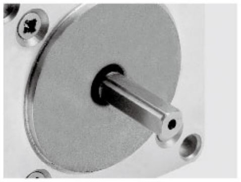
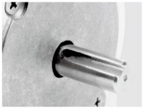
The captive linear stepper motor is a fully self-contained actuator designed for applications where precise linear motion is required without screw rotation. It includes an anti-rotation mechanism and a built-in guide system, ensuring the output shaft moves only linearly.
A captive linear stepper motor is a specialized type of stepper motor designed to generate linear motion instead of rotational motion. The term "captive" indicates that the motor features an integrated nut that is securely held in place by a housing or sleeve. This design ensures that the nut moves along the lead screw while preventing it from disengaging or rotating independently, which enables precise and consistent linear movement.
Key Features
Integrated anti-rotation and guiding components
Compact and enclosed design
Output shaft moves linearly, not rotationally
Advantages
Simplifies installation and system design
Provides precise, repeatable motion
Protects against contamination and wear
Low maintenance and long operational life
How It Works
When the motor is energized, the internal rotor rotates, moving the lead screw nut linearly. A slider rod connected to the nut transfers this motion externally while preventing rotational movement. This design eliminates the need for external guiding systems.
Typical Applications
A linear actuator stepper motor is an advanced motion control device that combines the rotary precision of a stepper motor with a linear mechanical system to produce highly accurate linear motion. These motors are the backbone of modern automation, CNC machinery, robotics, medical devices, and industrial positioning systems.
To fully understand how a linear actuator stepper motor delivers precise, repeatable motion, it’s essential to explore its key components. Each element plays a vital role in converting electrical input signals into controlled mechanical movement.
1. Stepper Motor
At the heart of every linear actuator stepper motor lies the stepper motor itself — an electromechanical device that divides a full rotation into a series of discrete steps.
Function
Each input pulse energizes a set of electromagnetic coils within the stator, causing the rotor to move incrementally. This step-by-step rotation provides unparalleled position control and repeatability without the need for feedback sensors.
Key Characteristics
Step angles: Commonly 1.8° (200 steps per revolution) or 0.9° (400 steps per revolution)
Holding torque: Maintains precise position when stationary
Microstepping capability: Enhances resolution and smoothness
Frame sizes: Typically available in NEMA 8, 11, 17, 23, and 34
The stepper motor provides the rotational energy that drives the mechanical motion of the actuator.
2. Lead Screw or Ball Screw
The lead screw (or occasionally a ball screw) is one of the most critical components in converting the stepper motor’s rotary motion into linear displacement.
Function
When the motor shaft turns, the lead screw’s helical threads engage with a nut assembly, causing linear movement along the screw’s axis. The pitch of the screw determines the linear travel per revolution—a finer pitch yields higher resolution but slower motion, while a coarse pitch delivers higher speed but lower precision.
Types of Screws
Lead Screw: Standard choice for most applications; quiet and cost-effective
Ball Screw: Offers higher efficiency and lower friction, ideal for high-speed or heavy-load systems
Materials
Typically made from stainless steel or hardened alloy steel for durability and corrosion resistance.
3. Nut Assembly
The nut assembly (also called a drive nut or carriage nut) moves linearly along the lead screw when the motor rotates.
Function
It serves as the moving interface between the rotating screw and the linear output. The nut translates rotary motion into linear displacement with minimal friction and backlash.
Types of Nuts
Standard Nut: Basic design for general-purpose applications
Anti-Backlash Nut: Includes a spring-loaded mechanism to eliminate play, improving precision and repeatability
Self-Lubricating Nut: Made from polymer materials to reduce maintenance and friction
Key Properties
4. Linear Guide or Bearing System
The linear guide system or bearing assembly ensures smooth, stable, and accurate movement of the actuator along its travel path.
Function
It supports the moving components (nut, shaft, or carriage) while minimizing friction, misalignment, and unwanted vibration. Proper guidance guarantees parallel linear motion and prevents binding during operation.
Common Types
Ball Bearings: Provide high load capacity and smooth motion
Plain Bushings: Cost-effective, suitable for light loads
Linear Rail Guides: Used in precision systems for high accuracy and stiffness
Benefits
Enhances system stability
Extends actuator lifespan
Improves motion smoothness and accuracy
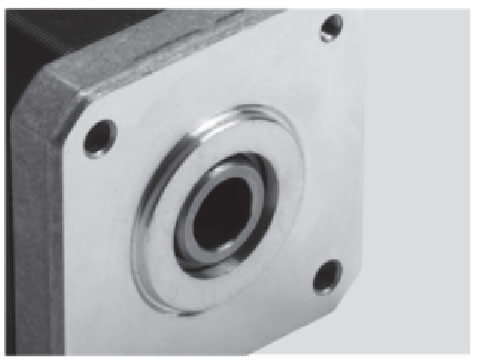
5. Housing and Mounting Structure
The housing is the protective enclosure that holds all mechanical and electrical components in alignment.
Function
It provides structural support, maintains shaft alignment, and protects internal parts from dust, debris, and external forces. The housing also aids in heat dissipation, ensuring efficient thermal management during continuous operation.
Material and Design
Typically made from aluminum alloy or stainless steel
Precision-machined for tight tolerances
May include mounting holes and flanges for easy system integration
A well-designed housing ensures mechanical integrity, vibration damping, and reliability in industrial environments.
6. Anti-Rotation Mechanism
In some linear actuator stepper motor designs—especially captive actuators—an anti-rotation mechanism is integrated to prevent the shaft or lead screw from spinning during operation.
Function
The anti-rotation mechanism guides the motion so that the output rod moves only linearly. It ensures smooth and precise movement without rotational slip.
Common Mechanisms
Guide rods and bushings
Linear keys or splines
Integrated slide rails
This component is crucial in systems where only linear output is desired, such as medical devices or valve actuators.
7. End Supports and Bearings
To maintain mechanical stability, the lead screw is supported at both ends by bearings or thrust washers.
Function
End supports prevent axial or radial play in the screw and ensure that it remains perfectly aligned with the motor shaft. This minimizes vibration, backlash, and mechanical wear during operation.
Types of Bearings
Radial Bearings: Handle rotational loads
Thrust Bearings: Support axial forces during motion
Angular Contact Bearings: Manage combined radial and thrust loads
High-quality bearing support enhances efficiency, precision, and longevity of the actuator.
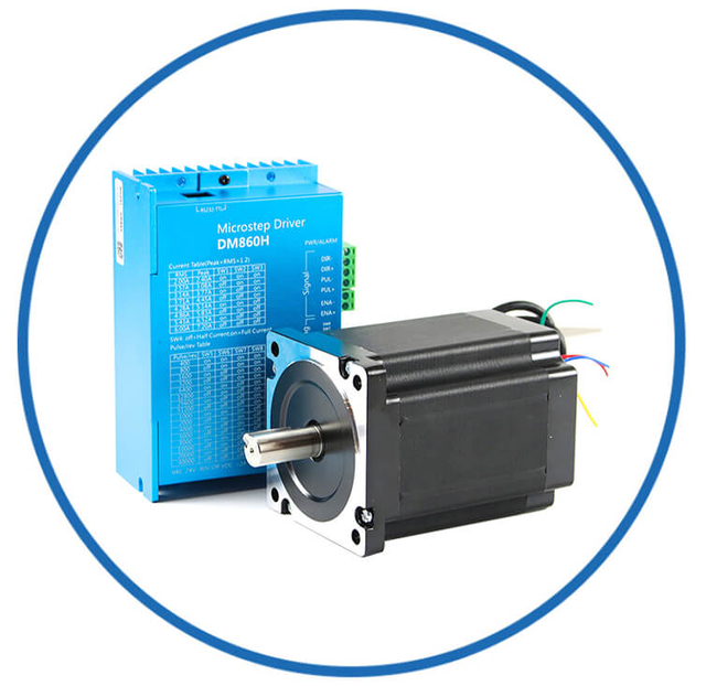
8. Stepper Driver and Control Electronics
The stepper driver is the electronic control unit that delivers power pulses to the stepper motor coils. It plays a pivotal role in dictating the actuator’s speed, direction, and step resolution.
Function
The driver receives command signals from a controller (such as a PLC, Arduino, or microcontroller) and converts them into timed electrical pulses. Each pulse corresponds to a specific linear movement.
Advanced Features
Microstepping Control: Divides full steps into smaller increments for smoother operation
Current Limiting: Protects the motor and driver from overload
Direction and Pulse Control: Determines travel direction and speed
Closed-loop feedback (optional): Enhances accuracy and stability
Together with the controller, the driver forms the electronic brain of the actuator system.
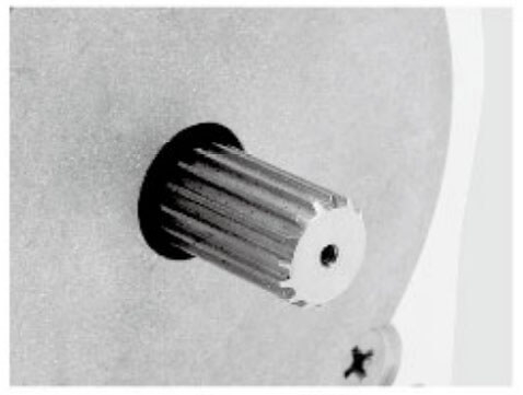
9. Coupling System
A coupler connects the stepper motor shaft to the lead screw (if not integrated). It ensures accurate transmission of torque without misalignment or vibration.
Types of Couplings
Rigid Couplers: For direct, high-torque transfer
Flexible Couplers: Compensate for minor misalignments and reduce stress
Oldham or Helical Couplers: Provide smooth torque transmission with vibration damping
Proper coupling guarantees efficient power transfer and prevents premature wear of motor and screw components.
10. Optional Sensors and Feedback Devices
While most stepper actuators operate in open-loop mode, certain high-precision systems integrate feedback sensors for closed-loop control.
Common Sensors
Encoders: Track position and speed
Limit Switches: Define travel boundaries and prevent overextension
Hall Sensors: Detect step position for synchronization
These components enhance system reliability, accuracy, and performance under dynamic loads.
| Component | Primary Function | Key Benefit |
| Stepper Motor | Provides rotary motion | High positional accuracy |
| Lead/Ball Screw | Converts rotation to linear motion | Smooth and precise displacement |
| Nut Assembly | Transfers motion to load | Reduces backlash and wear |
| Linear Guide | Ensures motion stability | Smooth linear movement |
| Housing | Structural support | Protection and heat dissipation |
| Anti-Rotation Mechanism | Prevents screw spin | Pure linear motion |
| End Bearings | Stabilize lead screw | Reduces vibration and noise |
| Stepper Driver | Controls pulses and direction | Customizable motion control |
| Coupling System | Connects motor to screw | Efficient torque transmission |
| Sensors (optional) | Feedback and safety | Enhanced precision and monitoring |
Conclusion
The performance of a linear actuator stepper motor depends heavily on the quality and integration of its components. Each part—from the stepper motor to the lead screw, nut assembly, and driver electronics—contributes to its overall precision, reliability, and responsiveness.
By understanding these key components, engineers and designers can select or build a linear actuator stepper system that perfectly matches their application’s speed, load, and accuracy requirements.
The working principle of a linear actuator stepper motor is based on electromechanical conversion and threaded transmission.
When a stepper driver sends current pulses to the motor windings, the magnetic field generated causes the rotor to move by one step. This incremental rotation of the shaft is transmitted through the lead screw, translating rotational motion into precise linear displacement of the nut.
By controlling the pulse frequency and direction, users can determine the speed, direction, and distance of the actuator’s linear movement. The higher the pulse rate, the faster the movement. When no pulses are sent, the actuator holds its position firmly thanks to the motor’s detent torque.
The Basic Principle of Operation
The working principle of a linear actuator stepper motor is based on two main processes:
Electromagnetic rotation of the stepper motor.
Mechanical conversion of rotary motion into linear motion through a threaded mechanism.
When an electrical pulse is applied to the stepper motor’s coils, the electromagnetic field generated causes the rotor to align with the energized stator teeth. Each pulse shifts the rotor by a fixed angular increment (a “step”).
This rotary stepping motion is then translated into linear motion by the lead screw, which engages a nut assembly that moves linearly along its axis.
Step-by-Step Working Process
Let’s break down how a linear actuator stepper motor operates from the moment it receives a command signal to when it delivers precise linear movement.
1. Pulse Signal Input
The stepper driver receives digital pulse signals from a motion controller (PLC, Arduino, or other control systems). Each pulse represents a discrete step of the motor shaft.
2. Electromagnetic Coil Activation
Inside the stator, multiple coils are arranged in specific phases. As the driver energizes these coils in sequence, it creates a rotating magnetic field.
The rotor, which contains permanent magnets or soft iron teeth, follows this field, moving incrementally by one step angle (commonly 1.8° for 200 steps per revolution).
3. Shaft Rotation
As current pulses continue, the rotor completes step-by-step rotation. The speed of rotation depends on the frequency of input pulses, while the direction is determined by the sequence in which the coils are energized.
4. Screw-to-Nut Conversion
The rotating shaft is connected to a lead screw or ball screw, which engages a nut assembly. This nut is fixed in place so that when the screw rotates, it translates rotary motion into linear displacement.
The distance the nut moves per revolution is determined by the lead screw pitch—the linear distance traveled per one complete revolution of the screw.
5. Linear Motion Output
As the lead screw continues to turn, the nut moves linearly along the axis, pushing or pulling the connected load. This produces a precise, smooth linear movement that corresponds directly to the number of input pulses.
6. Holding Position
When the pulses stop, the stepper motor naturally holds its position due to its detent torque—a magnetic locking force that prevents unwanted motion without continuous power.
This allows the actuator to maintain its position under load, a major advantage for static holding applications.
The performance of a linear actuator stepper motor depends heavily on its control electronics, typically consisting of three key parts:
1. Motion Controller
The controller sends pulse trains (step and direction signals) based on the desired position, speed, and acceleration.
2. Stepper Driver
The driver amplifies and translates the controller’s signals into current pulses that energize the motor coils. It determines:
3. Power Supply
A regulated power source provides stable voltage and current to ensure consistent motor torque and smooth operation.
Together, these components create a closed command loop that enables exact motion synchronization between electrical input and linear output.
Types of Motion Control Modes
Modern linear actuator stepper motors can be controlled using different step modes, which influence their smoothness and precision:
Full-Step Mode
Each pulse drives the motor by one full step. This provides maximum torque but can produce noticeable vibration.
Half-Step Mode
Combines single and dual coil energization, doubling the resolution and reducing vibration.
Microstepping Mode
Divides each full step into multiple smaller steps (up to 256 microsteps per full step). This achieves:
Microstepping is the preferred mode for high-precision motion control applications.
The conversion mechanism between rotary and linear motion can vary depending on the actuator design. The three most common configurations are:
External Linear Type:
The screw extends outside the motor body, allowing longer strokes and external load mounting.
Non-Captive Type:
The lead screw passes through the motor body, and the nut is built into the rotor. The screw moves linearly as the rotor turns.
Captive Type:
Features a built-in anti-rotation mechanism and a guided output rod that moves linearly without rotating. Ideal for compact, enclosed systems.
Each configuration provides different benefits in terms of stroke length, installation, and application flexibility.
Advantages of Stepper-Based Linear Actuators
The combination of a stepper motor and a linear motion system provides significant advantages:
High Positional Accuracy: Each pulse translates into a fixed, measurable linear step.
Repeatability: Excellent for applications requiring identical movement cycles.
Open-Loop Control: Eliminates the need for encoders or feedback systems.
Stable Holding Torque: Maintains load position without constant power.
Compact Design: Combines motor and actuator into one efficient unit.
Smooth Operation: Especially with microstepping drivers.
Example Application Scenario
Imagine a 3D printer’s Z-axis controlled by a NEMA 17 linear stepper actuator.
When the printer software sends a command to move the platform up by 2 mm, the controller calculates the exact number of pulses required based on the lead screw pitch. The driver then energizes the coils accordingly, turning the motor shaft the precise number of steps to achieve a 2 mm lift—with perfect repeatability, layer after layer.
This same principle applies across industries—from syringe pumps in medical labs to camera lens focus systems in imaging technology.
Key Factors Affecting Performance
The accuracy and efficiency of a linear actuator stepper motor depend on several parameters:
Step angle and microstepping resolution
Lead screw pitch and friction
Load weight and inertia
Driver current settings and voltage supply
Operating temperature and lubrication
Proper tuning of these factors ensures maximum torque, minimum vibration, and long operational life.
Conclusion
A linear actuator stepper motor works by transforming digital pulse signals into precisely controlled linear movement through the synchronized interaction of electromagnetic coils, rotor motion, and a threaded lead screw system.
This simple yet powerful mechanism enables highly accurate positioning, smooth motion, and long-term reliability—qualities that make it indispensable in modern automation, robotics, and precision manufacturing.
Understanding its working principle not only aids in selecting the right model but also in optimizing system performance for your specific application.
Linear actuator stepper motors offer multiple advantages over traditional actuators, including:
1. High Precision and Repeatability
With exact step increments and precise screw pitch, these actuators achieve micron-level accuracy—ideal for demanding motion control applications.
2. Simplified Control
Because stepper motors operate in an open-loop system, there’s no need for feedback sensors, reducing complexity and cost.
3. Excellent Holding Torque
The inherent torque of the stepper motor allows the actuator to maintain position under load even without power input.
4. Long Life and Reliability
Fewer moving parts, high-quality bearings, and minimal wear translate to long service life and consistent performance.
5. Flexible Configurations
Available in NEMA standard sizes (such as NEMA 8, 11, 17, 23, and 34), these actuators can be customized for specific travel lengths, load capacities, and speeds.
6. Quiet and Smooth Operation
Modern stepper drivers enable microstepping control, reducing vibration and noise during motion.
Because of their precision, compactness, and reliability, linear actuator stepper motors are used in a wide range of industries:
1. 3D Printers and CNC Machines
Used for Z-axis control, tool positioning, and material feed systems, ensuring accurate layer deposition and smooth surface finishing.
2. Robotics
Enables precise gripper movement, arm extension, and sensor alignment in robotic automation.
3. Medical and Laboratory Equipment
Applied in syringe pumps, microscope stages, sample handlers, and diagnostic instruments that require controlled motion.
4. Industrial Automation
Drives valves, actuators, conveyors, and linear stages in smart manufacturing systems.
5. Optical and Laser Systems
Ensures accurate focusing, beam alignment, and lens adjustment in laser engraving and measurement devices.
6. Aerospace and Defense
Used for control surfaces, positioning optics, and instrument calibration in harsh environments.
Selecting the best linear actuator stepper motor for your application involves evaluating several factors:
1. Load Requirements
Determine the maximum load (thrust) the actuator needs to move. Heavier loads require motors with higher torque or larger screw diameters.
2. Travel Distance
The required stroke length influences whether you choose a captive, non-captive, or external type actuator.
3. Speed vs. Resolution
Fine-pitch screws offer higher resolution but slower movement. Coarse-pitch screws deliver faster travel at lower precision.
4. Power and Voltage
Match the motor’s rated voltage and current with the stepper driver to ensure optimal performance.
5. Environment
Consider temperature, humidity, and potential contaminants when selecting housing and materials.
6. Integration and Mounting
Verify compatibility with your system’s mechanical interface, whether it’s a NEMA 17 frame for compact applications or a NEMA 23 for higher torque needs.
The future of linear actuator stepper motors lies in smart automation and IoT integration. Emerging trends include:
Closed-loop hybrid stepper systems with feedback for enhanced accuracy
Miniaturized actuators for wearable and medical devices
Energy-efficient drives for sustainable automation
Advanced control algorithms for smoother and quieter operation
Integrated driver electronics reducing system footprint
As automation evolves, stepper-based linear actuators will continue to power innovations that demand compactness, efficiency, and precision.
Conclusion
The linear actuator stepper motor represents a perfect balance of mechanical precision and electronic control. Its ability to translate digital pulses into accurate linear motion makes it indispensable across modern industries. Whether for 3D printing, medical automation, or robotic motion, this technology delivers unparalleled performance, consistency, and reliability.