Stepper motors are the backbone of precision motion systems used in robotics, CNC machinery, 3D printers, and industrial automation. Among their many performance parameters, torque stands out as one of the most critical. Understanding how much torque a stepper motor can produce—and what factors influence it—is essential for designing reliable and efficient motion control systems.
In this comprehensive guide, we will explore stepper motor torque characteristics, types, influencing factors, torque–speed relationships, and techniques to maximize performance.
Stepper motor torque refers to the rotational force a stepper motor can generate to move or hold a load. It is one of the most important parameters that determines how effectively the motor can perform in applications such as 3D printers, CNC machines, robotics, and automation systems.
Torque in a stepper motor is typically measured in Newton-meters (N·m) or ounce-inches (oz·in). It defines how much twisting force the motor's shaft can apply to drive mechanical components like gears, belts, or lead screws.
There are two main types of torque in stepper motors:
Holding Torque – This is the maximum torque a stepper motor can maintain when it is energized but not rotating. It represents the motor's ability to hold a position firmly against an external force. For example, in CNC machines, strong holding torque ensures the cutting head stays fixed in place when the motor stops.
Pull-Out Torque – This is the maximum torque a motor can deliver at a specific speed before it loses synchronization (i.e., starts skipping steps). Pull-out torque decreases as the speed increases, meaning stepper motors deliver their best torque performance at low to medium speeds.
The torque performance of a stepper motor depends on several factors, including supply voltage, winding current, inductance, motor size, and driver configuration. Engineers often use a torque–speed curve to understand how torque varies with speed and to ensure the motor is operated within its safe and efficient range.
In short, understanding stepper motor torque is essential for selecting the right motor for a given application. A motor with insufficient torque may fail to move the load accurately, while an oversized motor can waste energy and increase system cost.
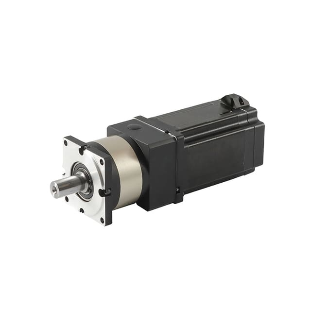
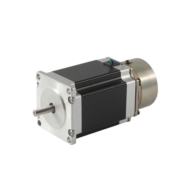
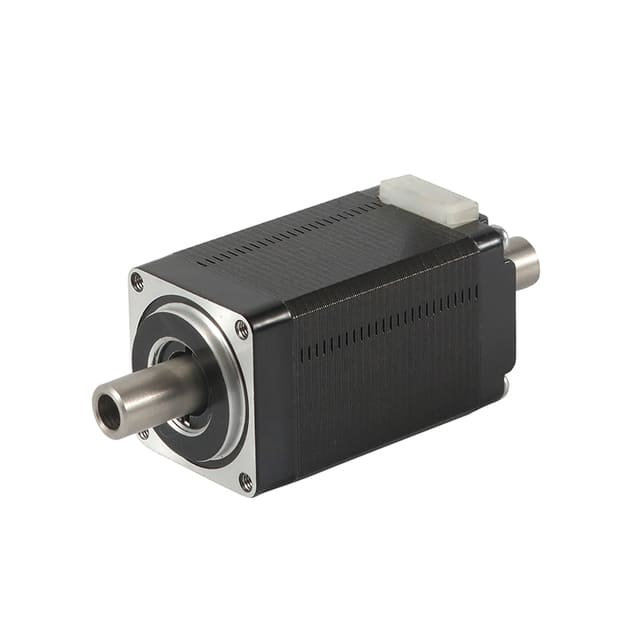
![Brake Stepper Motor]()
Brake Stepper Motors
Types of Stepper Motors and Their Torque Capabilities
Stepper motors come in several types, each designed with distinct characteristics that affect how much torque they can produce and how efficiently they operate. The three main types of stepper motors are Permanent Magnet (PM), Variable Reluctance (VR), and Hybrid stepper motors. Understanding their differences helps in choosing the right motor for specific torque and performance requirements.
1. Permanent Magnet (PM) Stepper Motors
Permanent Magnet stepper motors use a rotor made of a permanent magnet that interacts with the electromagnetic fields of the stator. These motors are relatively simple in design and are known for their smooth motion and good holding torque at low speeds.
Torque Range: Typically from 0.1 N·m to 1.0 N·m (14 oz·in to 140 oz·in)
Advantages: Low cost, compact design, and good low-speed performance
Limitations: Limited speed range and lower torque output compared to hybrid types
Common Applications: Small robotics, printers, instruments, and basic positioning systems
PM stepper motors are ideal for light-duty applications where fine control is needed but high torque is not critical.
2. Variable Reluctance (VR) Stepper Motors
Variable Reluctance stepper motors have a soft iron rotor with multiple teeth but no permanent magnets. Torque is generated when the stator's magnetic field attracts the nearest rotor teeth, causing rotation.
Torque Range: Around 0.05 N·m to 0.5 N·m (7 oz·in to 70 oz·in)
Advantages: Capable of high stepping rates and fast response times
Limitations: Lower holding torque, less efficient at low speeds, and more prone to vibration
Common Applications: Laboratory automation, high-speed actuators, and light industrial devices
Although VR motors can achieve high stepping speeds, their torque is generally lower than that of PM or Hybrid types.
Hybrid stepper motors combine the features of both PM and VR stepper motors. They include a toothed permanent magnet rotor and a precisely wound stator, providing high torque, accuracy, and efficiency.
Torque Range: Typically from 0.2 N·m to over 20 N·m (28 oz·in to 2800 oz·in), depending on motor size and current
Advantages: High torque density, excellent positional accuracy, and smooth rotation
Limitations: Higher cost and more complex design
Common Applications: CNC machinery, 3D printers, medical equipment, and industrial automation
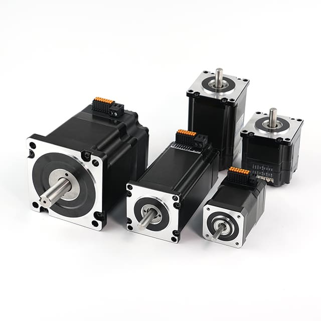
Hybrid stepper motors are available in various frame sizes such as NEMA 17, 23, 34, and 42, each offering progressively higher torque. For instance:
NEMA 17: 0.3–0.6 N·m
NEMA 23: 1.0–3.0 N·m
NEMA 34: 4.0–12.0 N·m
NEMA 42: 15–30 N·m
These motors are the most popular choice for demanding applications where high holding torque and precise positioning are essential.
Summary
| Stepper Motor Type | Torque Range (N·m) | Key Advantages | Typical Applications |
| Permanent Magnet (PM) | 0.1 – 1.0 | Compact, smooth at low speed | Robotics, printers, instruments |
| Variable Reluctance (VR) | 0.05 – 0.5 | High stepping rate | Light automation, actuators |
| Hybrid | 0.2 – 20+ | High torque and accuracy | CNC, medical, industrial automation |
In conclusion, Hybrid stepper motors offer the highest torque and are the most versatile among all types, while PM and VR stepper motors serve best in lightweight or specialized applications. Selecting the right motor type ensures the perfect balance between torque output, precision, speed, and cost for any motion control system.
Torque–Speed Characteristics of Stepper Motors
The torque–speed characteristics of a stepper motor describe how the motor's torque output changes with speed. Understanding this relationship is essential when selecting a motor for a specific application, as it determines how effectively the motor can drive a load across different operating conditions.
Unlike traditional DC motors, stepper motors produce maximum torque at low speeds and experience a gradual decrease in torque as speed increases. This unique behavior results from the electrical and magnetic properties of the motor's windings and the time required for current to build up in each phase.
1. The Basic Torque–Speed Curve
The torque–speed curve is a graphical representation showing how torque varies with motor speed. It typically includes two important regions:
Low-Speed Region (Constant Torque Zone)
In this region, the current in each winding has enough time to reach its maximum level during every step. Therefore, the motor produces maximum torque, often referred to as holding torque or pull-in torque. The motor can start, stop, or reverse direction without losing synchronization.
High-Speed Region (Falling Torque Zone)
As the motor speed increases, the inductance of the windings prevents the current from reaching its peak value quickly. This results in a drop in torque output. Eventually, at very high speeds, the motor cannot generate enough torque to maintain synchronization, leading to step loss or stalling.
2. Pull-In and Pull-Out Torque
Two key torque limits are identified from the torque–speed curve:
Pull-In Torque Curve:
The maximum torque at which a stepper motor can start, stop, or reverse without losing steps. Operation within this region ensures stable motion and reliable positioning.
Pull-Out Torque Curve:
The maximum torque the motor can sustain while running at a given speed. Exceeding this limit causes the rotor to lose synchronization with the stator's magnetic field, resulting in missed steps or total stall.
Between the pull-in and pull-out curves, the motor can operate reliably if acceleration and deceleration are properly controlled.
3. Example of a Typical Torque–Speed Relationship
A NEMA 23 hybrid stepper motor might exhibit the following approximate performance:
| Speed (rpm) | Available Torque (N·m) |
| 0 rpm (Holding) | 2.0 N·m |
| 300 rpm | 1.5 N·m |
| 600 rpm | 1.0 N·m |
| 900 rpm | 0.5 N·m |
| 1200 rpm | 0.2 N·m |
This example demonstrates that while the motor provides high torque at low speeds, it rapidly declines as rotational speed increases.
4. Factors Affecting the Torque–Speed Curve
Several parameters influence the shape and performance of a stepper motor's torque–speed curve:
Supply Voltage:
A higher drive voltage allows current to rise faster in the windings, improving torque at higher speeds.
Drive Current:
Increasing current enhances torque output but also raises heat generation.
Winding Inductance:
Motors with lower inductance maintain torque better at higher speeds because the current can build more rapidly.
Driver Type:
Advanced chopper drivers and microstepping controllers can optimize current flow, improving overall torque response and smoothness.
Load Inertia:
Heavy loads with high inertia reduce acceleration capability and can cause torque loss or step skipping at high speeds.
5. Resonance and Stability Considerations
Stepper motors can experience resonance at certain speeds, leading to vibrations or torque oscillations. This occurs when the natural frequency of the motor and load system aligns with the stepping frequency. To counter this, engineers can:
Use microstepping to smooth motion,
Implement damping mechanisms, or
Employ closed-loop stepper systems with feedback to maintain synchronization.
6. Improving Torque–Speed Performance
To maximize torque across a wider speed range, several techniques can be applied:
Increase the supply voltage (within driver limits) for faster current response.
Choose motors with low inductance windings.
Use optimized acceleration profiles to stay within safe torque limits.
Apply current-controlled stepper drivers to ensure efficient torque generation.
7. Summary
In summary, the torque–speed characteristics of stepper motors define how torque declines as speed rises due to inductance and current limitations. The curve highlights key operational regions—constant torque at low speed and decreasing torque at high speed. By understanding and optimizing these dynamics, designers can select and operate stepper motors that deliver maximum performance, stability, and precision for any given application.
Factors Affecting Stepper Motor Torque Output
Several design and operational parameters influence the torque a stepper motor can produce:
1. Supply Voltage
Increasing the drive voltage allows current to rise more quickly in the windings, which improves high-speed torque. However, excessive voltage may cause overheating or damage insulation, so a compatible driver and motor rating must be maintained.
2. Drive Current
The torque of a stepper motor is directly proportional to the current through its windings. Using a driver that can deliver higher current (within motor limits) will increase torque. Current limiting features in stepper drivers ensure safe operation.
3. Winding Inductance
Motors with lower inductance windings can change current faster, resulting in better high-speed torque. High inductance windings, while offering higher holding torque, perform poorly at higher speeds.
4. Microstepping
Microstepping drivers subdivide each full step into smaller steps for smoother motion. However, microstepping reduces peak torque output because the current is distributed across multiple phases. In precision applications, this trade-off is often acceptable for smoother control.
5. Motor Size (Frame Type)
Larger frame motors naturally generate more torque. For example:
NEMA 17: 0.3–0.6 N·m
NEMA 23: 1.0–3.0 N·m
NEMA 34: 4.0–12.0 N·m
NEMA 42: 15–30 N·m
Choosing the right motor frame size ensures adequate torque for the intended load.
6. Rotor Inertia and Load Characteristics
If the rotor or load has high inertia, the motor must deliver greater torque to accelerate it without losing steps. Matching the inertia ratio (load to motor) is vital for stable operation.
7. Temperature
Stepper motor torque decreases with temperature. High winding temperatures increase resistance, which limits current flow and reduces torque. Proper cooling, ventilation, or heat sinking helps maintain consistent performance.
Maximizing the torque output of a stepper motor is crucial for achieving the best performance in motion control systems such as CNC machines, robotics, and automation equipment. Since torque directly determines how effectively the motor can drive a mechanical load, optimizing it ensures smoother operation, higher precision, and improved reliability. Below are the most effective methods to increase and maintain maximum torque from a stepper motor.
1. Use an Appropriate Power Supply Voltage
Stepper motor torque, especially at high speeds, is greatly influenced by the supply voltage. A higher voltage enables the current in the windings to rise faster, countering the effects of inductance. This allows the motor to maintain torque even as speed increases.
However, the supply voltage must be carefully matched to the driver's rated voltage and the motor's insulation limits to avoid overheating or damage. For example, a motor rated at 3 V can often be driven using 24 V or more—as long as a current-limiting driver is used to regulate the current safely.
Key point: Increasing voltage improves high-speed torque without affecting low-speed performance.
2. Increase Drive Current (Within Limits)
Torque in a stepper motor is directly proportional to the current through its windings. By increasing the drive current (within the rated limits), the motor produces a stronger magnetic field and higher torque output.
Modern chopper drivers allow precise control of current levels, enabling motors to run at higher torque safely without overheating.
Tip: Check the manufacturer's datasheet to ensure the motor's maximum rated current is not exceeded to maintain efficiency and prevent insulation damage.
3. Use Low-Inductance Motors for High-Speed Applications
Stepper motors with low winding inductance allow the current to build up more rapidly in each coil, resulting in better torque at higher speeds. High-inductance motors, while producing stronger torque at low speeds, tend to lose torque quickly as speed increases.
If your application involves rapid movements or high-speed positioning, a low-inductance hybrid stepper motor combined with a higher supply voltage will deliver better overall torque performance.
4. Optimize Microstepping Settings
Microstepping divides each full step into smaller steps, providing smoother motion and finer resolution. However, this technique slightly reduces peak torque because the current is distributed among multiple windings.
To maximize torque while maintaining smoothness:
Use 1/4 or 1/8 microstepping instead of very high subdivisions like 1/32 or 1/64.
Tune microstepping settings to balance torque, resolution, and smoothness according to your system's requirements.
Note: For applications where torque is more critical than smoothness, full-step or half-step modes may be preferred.
5. Maintain Proper Motor Cooling
Excessive heat reduces torque output by increasing the resistance of the windings and weakening the magnetic field. To ensure consistent torque:
Provide adequate airflow or cooling fans around the motor.
Use heat sinks on high-performance or continuously running motors.
Avoid running motors at full current continuously when unnecessary.
Keeping the operating temperature below 80°C (176°F) helps preserve torque and motor life.
Modern stepper drivers are designed with features that significantly improve torque efficiency and motion performance. Look for drivers that include:
Current control (chopper drive) for precise torque regulation
Anti-resonance algorithms to reduce vibration and torque loss
Dynamic current adjustment for optimal torque across varying speeds
A closed-loop stepper driver (servo stepper system) can further enhance torque by adjusting current dynamically based on real-time load conditions, ensuring maximum performance without overheating.
7. Optimize Acceleration and Deceleration Profiles
Sudden starts or rapid acceleration can cause a stepper motor to lose synchronization or skip steps, reducing effective torque. To avoid this:
Proper motion profiling ensures the motor operates within its stable torque zone throughout its speed range.
8. Match Load Inertia to Motor Inertia
A mismatch between the load's moment of inertia and the motor's rotor inertia can lead to torque inefficiencies and instability.
If the load inertia is too high, the motor must deliver more torque to accelerate it, potentially causing step loss.
If too low, the system may experience oscillations and poor damping.
Ideally, the load-to-rotor inertia ratio should be kept below 10:1 for optimal torque response and smooth motion.
9. Reduce Mechanical Friction and Load Resistance
Unnecessary friction, misalignment, or mechanical binding in the system can waste torque and reduce performance. To minimize losses:
Use low-friction bearings and linear guides.
Keep all shafts and couplings properly aligned.
Lubricate moving parts periodically.
Reducing mechanical resistance ensures that most of the motor's torque is effectively used to move the intended load.
Closed-loop stepper motors combine the precision of stepper operation with the adaptability of servo control. They use feedback sensors (encoders) to monitor position and adjust current in real-time.
Benefits include:
Higher usable torque across the speed range
No missed steps, even under variable loads
Cooler operation due to optimized current usage
This makes closed-loop systems ideal for demanding industrial applications that require both high torque and precise motion control.
Summary: Key Ways to Maximize Stepper Motor Torque
| Method | Effect on Torque | Notes |
| Increase supply voltage | Boosts high-speed torque | Use current-limited driver |
| Raise drive current | Increases overall torque | Stay within rated limits |
| Use low-inductance motor | Improves high-speed torque | Best for fast systems |
| Optimize microstepping | Balances torque and smoothness | Avoid excessive subdivision |
| Improve cooling | Maintains torque consistency | Use fans or heat sinks |
| Use advanced drivers | Enhances efficiency | Prefer chopper or closed-loop types |
| Optimize motion profiles | Prevents torque loss | Smooth acceleration and deceleration |
| Match load inertia | Improves stability | Keep inertia ratio < 10:1 |
| Minimize friction | Reduces torque loss | Ensure proper alignment |
| Use closed-loop control | Maximizes torque utilization | Ideal for heavy-duty tasks |
Conclusion
Maximizing stepper motor torque involves a combination of electrical optimization, mechanical design, and intelligent control strategies. By carefully managing voltage, current, inductance, microstepping, and cooling, and by employing advanced driver technologies and feedback control, engineers can achieve the highest possible torque output for any given application.
A well-optimized stepper motor system ensures greater efficiency, precision, and durability, delivering superior performance across industrial and automation environments.
Typical Torque Values for Common Stepper Motor Sizes
| Motor Type | Frame Size | Holding Torque (N·m) | Typical Applications |
| PM Stepper | 20 mm | 0.1 – 0.3 | Printers, instrumentation |
| Hybrid Stepper | NEMA 17 | 0.3 – 0.6 | 3D printers, small robotics |
| Hybrid Stepper | NEMA 23 | 1.0 – 3.0 | CNC routers, automation |
| Hybrid Stepper | NEMA 34 | 4.0 – 12.0 | Industrial machinery |
| Hybrid Stepper | NEMA 42 | 15 – 30 | Heavy-duty CNC, gantry systems |
Conclusion
The torque a stepper motor can produce depends on multiple interrelated factors—motor design, electrical parameters, driver configuration, and mechanical load. Hybrid stepper motors, particularly in NEMA 23 to NEMA 42 sizes, offer the highest torque ranges, often exceeding 20 N·m for industrial use. By optimizing voltage, current, driver selection, and load matching, engineers can extract maximum torque and precision from their systems.