In the world of precision automation and motion control, NEMA 17 linear actuator stepper motors stand as a perfect combination of power, accuracy, and versatility. Whether used in 3D printers, CNC machinery, robotics, or medical devices, these motors deliver outstanding performance where linear motion and fine positioning are critical.
In this guide, we explore everything you need to know about NEMA 17 linear actuator stepper motors, from their design principles and key features to applications, advantages, and selection criteria—helping engineers and manufacturers make the right choice for their motion systems.
What Is a NEMA 17 Linear Actuator Stepper Motor?
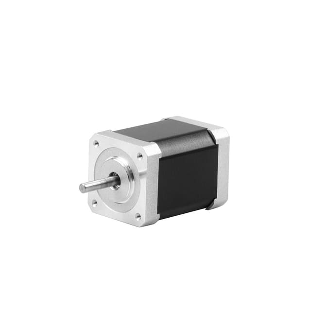
A NEMA 17 linear actuator stepper motor is a hybrid stepper motor built according to the NEMA (National Electrical Manufacturers Association) standard with a 1.7 x 1.7-inch (43.2 x 43.2 mm) faceplate. Unlike conventional stepper motors that produce rotational motion, these motors are designed to convert rotary motion into precise linear motion through an integrated lead screw mechanism.
This design eliminates the need for external coupling or linear translation assemblies, resulting in compact, efficient, and backlash-free motion.
Main Types of NEMA 17 Linear Stepper Motors
There are three primary types of NEMA 17 linear stepper motors, classified based on how the lead screw and nut mechanism are designed and how the linear motion is generated:
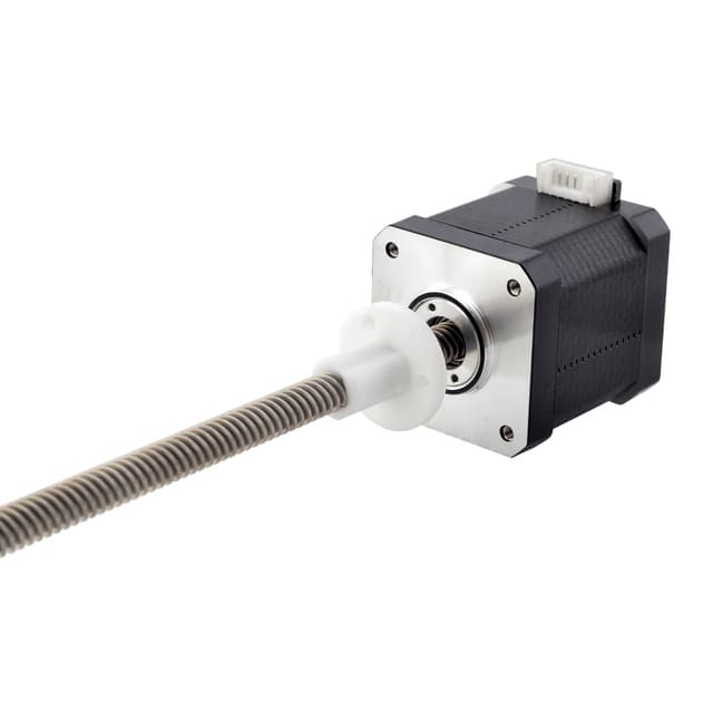
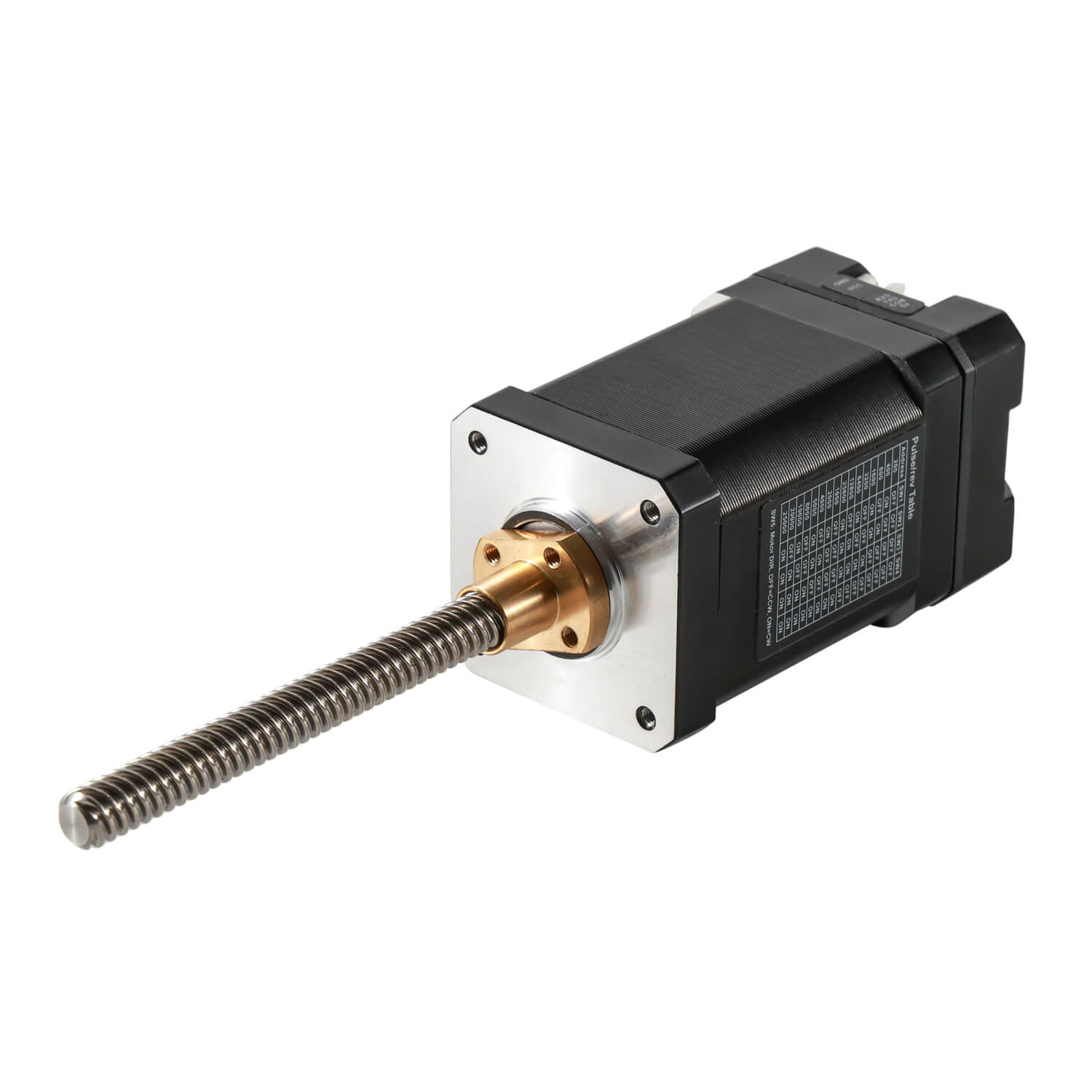
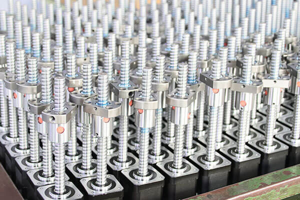
The external linear actuator type features a lead screw that extends outside the motor housing, allowing longer travel distances. As the rotor turns, the lead screw moves in and out, translating the rotational steps into precise linear displacement.
Key Features
The lead screw rotates while the nut is fixed.
Provides longer stroke lengths than other types.
Easy to integrate with external assemblies and moving platforms.
Ideal for applications requiring long travel but limited force.
Typical Applications
Advantages
Offers extended motion range.
Simple and cost-effective design.
Compatible with a variety of lead screw lengths and pitches.
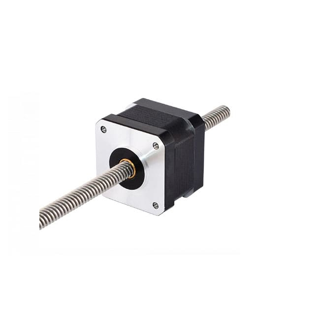
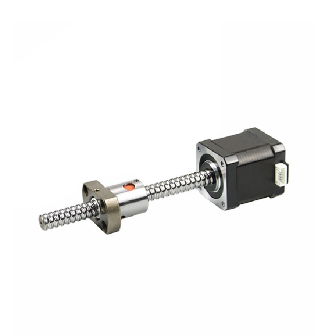
In the non-captive type, the lead screw does not move in or out of the motor body. Instead, it rotates internally, and a nut assembly (mounted to the load) moves linearly along the screw.
This configuration eliminates the need for anti-rotation mechanisms but requires the load or mounting system to prevent rotation of the nut.
Key Features
The lead screw is fixed within the motor.
The nut translates linearly as the screw rotates.
Offers compact design for limited-space environments.
Requires an external guide system for linear alignment.
Typical Applications
Precision positioning systems
Optical adjustment mechanisms
Small automation equipment
Micro-dispensing systems
Advantages
Compact and space-saving design.
Allows high-precision micro-positioning.
No external coupling required between motor and screw.
The captive linear actuator integrates both the lead screw and anti-rotation guide mechanism inside the motor body. A pushrod or shaft extends from the motor, moving in and out without the need for external guides.
This design prevents the screw from rotating, ensuring direct and smooth linear motion—ideal for vertical lifting or push-pull motion applications.
Key Features
Includes an anti-rotation guide or slide mechanism.
The shaft moves linearly without rotating.
Provides controlled, precise linear movement.
Easy to mount and integrate in plug-and-play designs.
Typical Applications
Advantages
Delivers accurate, repeatable motion with no external guides.
Self-contained assembly simplifies installation.
Suitable for vertical or horizontal motion.
| Feature | External Type | Non-Captive Type | Captive Type |
| Lead Screw Movement | Extends outside motor | Stays internal | Shaft extends linearly |
| Nut Movement | Fixed | Moves linearly | Fixed internally |
| Anti-Rotation Mechanism | External | Required externally | Built-in |
| Travel Distance | Long | Moderate | Limited |
| Installation Complexity | Low | Medium | Low |
| Typical Use | Long-travel stages | Compact systems | Direct linear motion |
| Precision Level | Medium | High | Very High |
Conclusion
The NEMA 17 linear stepper motor is a versatile and powerful actuator that brings precise linear control to compact mechanical systems. Whether you choose the external, non-captive, or captive type, each offers unique benefits tailored to specific load, space, and motion demands.
Understanding the distinctions between these types ensures optimal performance, accuracy, and reliability in your automation or robotics projects.
With their high repeatability, low maintenance, and flexible integration, NEMA 17 linear stepper motors continue to be an indispensable component in modern motion control technology.
The NEMA 17 linear actuator stepper motor is a crucial innovation in precision motion control, designed to convert rotational motion into linear displacement with exceptional accuracy. Compact, efficient, and highly controllable, it serves as a cornerstone in 3D printers, robotics, CNC systems, and medical devices.
Understanding the Basics of NEMA 17 Linear Actuator Stepper Motors
The term NEMA 17 refers to the mounting size standard defined by the National Electrical Manufacturers Association—specifically, a 1.7 x 1.7-inch (43.2 x 43.2 mm) faceplate. What sets the linear actuator version apart from a standard NEMA 17 stepper motor is the integration of a lead screw into the motor’s rotor.
Instead of generating rotational output, this motor is engineered to produce direct linear motion without requiring external mechanical components like belts or couplers. This built-in translation mechanism simplifies mechanical design and enhances system reliability.
The Working Principle of a NEMA 17 Linear Actuator Stepper Motor
At its core, the NEMA 17 linear actuator operates based on electromagnetic step sequencing—the same principle as a typical stepper motor. Each time a pulse of electrical current is sent to the stator windings, the rotor advances by a specific angular step (typically 1.8° per step, or 200 steps per revolution).
However, instead of outputting rotation, this rotational movement drives a lead screw, which, through its helical thread, converts the rotary motion into linear displacement. The resulting motion is incremental, precise, and repeatable, allowing fine control of linear positioning.
Key Components Involved in the Operation
The NEMA 17 linear actuator stepper motor is a compact assembly consisting of several precisely engineered parts that work together to achieve smooth, accurate linear motion.
1. Stator and Rotor
The stator contains multiple electromagnetic coils arranged in phases.
The rotor, made of permanent magnets, aligns with these magnetic fields as they are sequentially energized.
Each phase activation causes the rotor to rotate by a small, fixed step angle.
2. Lead Screw
Attached directly to the rotor shaft, the lead screw translates the rotary motion into linear motion.
Its thread pitch determines the distance moved per step—a finer pitch offers higher resolution, while a coarser pitch provides faster linear speed.
3. Lead Nut or Drive Nut
The nut engages with the lead screw threads, translating the screw’s rotation into linear movement.
It is usually made from brass, polymer, or anti-backlash material to minimize friction and wear.
4. Bearings
5. Housing
Step-by-Step Motion Conversion Process
Let’s take a closer look at the sequence of operations that enables a NEMA 17 linear actuator to perform linear movement:
Electrical Signal Input
The motor driver sends a controlled series of electrical pulses to the motor’s windings.
Magnetic Field Generation
Each energized coil creates a magnetic field that pulls the rotor’s permanent magnets into alignment.
Rotor Movement
As the drive circuit energizes the coils in a specific sequence, the rotor advances one step for every pulse received.
Lead Screw Rotation
Since the lead screw is directly coupled to the rotor, it rotates proportionally with the rotor’s steps.
Linear Displacement of the Nut or Shaft
The nut (or, in some designs, a sliding shaft) moves linearly along the screw’s axis, converting rotary motion into precise linear travel.
By controlling the pulse frequency and number of steps, engineers can precisely determine speed, direction, and position—achieving open-loop motion control with excellent repeatability.
Types of Linear Motion Configurations
The conversion of rotary motion to linear displacement depends on how the lead screw and nut are integrated. There are three main mechanical configurations of NEMA 17 linear actuators, each working slightly differently:
The lead screw extends outward from the motor.
As the motor turns, the screw itself moves in and out, producing linear motion.
Commonly used where long travel distances are required.
The lead screw remains inside the motor housing, rotating internally.
The nut moves linearly along the screw as it rotates.
Requires an external guide to prevent nut rotation.
Contains a built-in anti-rotation guide and a pushrod assembly.
The lead screw rotates internally, moving the pushrod in and out.
Provides precise, backlash-free linear motion without external mechanisms.
Each type uses the same stepper motion principle but applies it differently to achieve the desired travel, force, and control precision.
Electrical Control and Microstepping
To achieve smooth motion and fine positioning, NEMA 17 linear actuator stepper motors are controlled using microstepping drivers. Instead of energizing coils in full-step increments, microstepping divides each step into smaller electrical intervals, allowing up to 256 microsteps per full step.
This control technique results in:
Reduced vibration and noise
Smoother motion transitions
Higher positional accuracy
Improved torque stability at low speeds
Common driver ICs used for these motors include the A4988, DRV8825, and TMC2209, depending on the required voltage, current, and control resolution.
Performance Parameters
Several key parameters influence how effectively a NEMA 17 linear actuator operates:
| Parameter | Description |
| Step Angle | Typically 1.8° (200 steps per revolution) |
| Linear Resolution | Depends on lead screw pitch (e.g., 0.005 mm/step to 0.05 mm/step) |
| Holding Torque | 40 – 70 N·cm typical |
| Linear Force | Up to 200 N, depending on coil current |
| Rated Current | 1.2 – 2.0 A/phase |
| Operating Voltage | 12 – 48 V DC |
| Speed Range | 0 – 100 mm/s typical |
These specifications determine whether the actuator is optimized for speed, precision, or load handling.
Conclusion
The NEMA 17 linear actuator stepper motor operates through a seamless integration of electromechanical principles—transforming rotary steps into linear precision motion. By combining the accuracy of stepper control with the efficiency of lead screw mechanics, it delivers a powerful yet compact solution for countless automation applications.
With advancements in microstepping, feedback systems, and materials, NEMA 17 actuators continue to define the standard for precise, repeatable linear motion in modern engineering.
Technical Specifications
While configurations vary by manufacturer, typical NEMA 17 linear actuator specifications include:
Step Angle: 1.8° (200 steps per revolution)
Linear Resolution: 0.005 mm to 0.05 mm per step (depending on lead screw pitch)
Holding Torque: 40 – 70 N·cm
Linear Force: Up to 200 N (varies by lead screw and current)
Rated Current: 1.2 – 2.0 A per phase
Travel Speed: Up to 100 mm/s
Operating Voltage: 12V – 48V DC
These parameters make the NEMA 17 actuator an excellent balance between compactness and power output for medium-load applications.
1. High Precision and Repeatability
The microstepping control allows precise positioning down to micrometers, ideal for 3D printing, CNC routing, and laboratory instruments.
2. Compact All-in-One Design
By integrating the lead screw directly with the motor shaft, it reduces the need for external couplings, minimizing space usage and alignment errors.
3. Excellent Torque-to-Size Ratio
Despite their small frame, NEMA 17 actuators deliver impressive linear thrust, suitable for medium-load applications.
4. Maintenance-Free Operation
With fewer mechanical connections, no lubrication requirements, and robust stepper technology, they ensure long service life.
5. Easy Control Integration
Compatible with most stepper motor drivers and microcontrollers (such as Arduino, Raspberry Pi, or PLCs), they support open-loop or closed-loop control systems.
The versatility of NEMA 17 linear actuators enables their use across numerous industries:
3D Printers: For extruder head positioning and Z-axis control.
CNC Machines: Ensures accurate feed motion and depth control.
Robotics: Used for precise end-effector movements and automated gripping.
Medical Equipment: Provides micro-controlled motion in pumps, syringes, and diagnostic devices.
Optical and Measurement Systems: Enables fine adjustments in microscopes and camera focus mechanisms.
Automation and Assembly Lines: Perfect for pick-and-place operations and linear transport systems.
Their combination of accuracy, reliability, and cost-effectiveness makes them a preferred choice across these applications.
Future Trends in Linear Stepper Motor Technology
As automation continues to evolve, NEMA 17 linear actuator stepper motors are seeing continuous advancements, including:
Integration with Smart Drivers for feedback and diagnostics.
Closed-loop control systems using encoders for precise motion verification.
Miniaturization while maintaining torque output.
Advanced materials and lubrication-free bearings for extended durability.
Energy-efficient microstepping for quieter and smoother motion.
These innovations will further enhance their role in precision motion control, driving next-generation automation solutions.
Conclusion
The NEMA 17 linear actuator stepper motor represents a reliable, efficient, and precise motion solution that meets the demands of modern automation and robotics. Its integration of stepper control and linear actuation simplifies mechanical design while ensuring accurate, repeatable movement across a wide range of applications.
From CNC systems to medical automation, these motors continue to be the backbone of precision engineering, offering a perfect balance of power, compactness, and performance.