Stepper motors are one of the most widely used motion control devices in automation, robotics, and precision machinery. Their ability to offer precise control of angular position, speed, and acceleration makes them indispensable in various industries. However, one common question arises among engineers and enthusiasts alike — do stepper motors use AC or DC power? Understanding the type of current used by stepper motors is essential for selecting the right driver, controller, and power supply to achieve optimal performance.
Stepper motors are electromechanical devices that precisely convert electrical energy into mechanical motion. Unlike conventional DC motors, which rotate continuously when voltage is applied, a stepper motor moves in discrete, controlled steps. This step-by-step movement is achieved through the sequential energizing of stator windings, allowing for accurate control of position, speed, and rotation direction without the need for feedback sensors.
At their core, stepper motors operate on DC electrical power, which is transformed into pulsed electrical signals by a motor driver or controller. These pulses are then sent to the motor windings in a specific sequence. Each pulse creates a magnetic field within a winding, attracting the rotor’s teeth to align with the energized stator pole. When the sequence advances, the magnetic field shifts, causing the rotor to move one step forward.
This process continues as long as pulses are applied, and the frequency of these pulses directly determines the motor’s speed, while the number of pulses determines the distance or angle of rotation. Because of this precise correlation between electrical input and mechanical output, stepper motors are often chosen for high-precision applications such as CNC machines, 3D printers, medical devices, and robotics.
In summary, the electrical nature of a stepper motor is defined by:
DC power input, typically from a regulated power supply or battery.
Pulse-driven operation, where each pulse represents one incremental movement.
Electromagnetic interaction, which converts electrical signals into physical rotation.
This combination of electrical precision and mechanical control makes stepper motors a cornerstone of modern motion control systems.
Are Stepping Motors AC or DC? The Clear Answer
Stepper motors operate on DC power, not AC. However, the way this DC power is used inside the motor can make it appear as if it behaves like an AC device — which is why the distinction often causes confusion. In essence, stepper motors are DC-powered machines that rely on pulsed or modulated DC signals to generate motion. A stepper driver or controller takes in DC voltage from a power supply and converts it into a sequence of electrical pulses. These pulses are sent to the motor’s coils in a specific order, creating alternating magnetic fields that cause the rotor to move in discrete steps. Although these alternating magnetic fields resemble AC waveforms in appearance, they are not true AC currents. The source of energy remains DC, and the alternating effect comes from how the driver switches current between different windings in rapid succession.
To simplify:
• Power Source: DC (from a battery or regulated power supply) • Control Signals: Pulsed or alternating DC (generated by the driver) • Motor Operation: Step-by-step rotation controlled by timed DC pulses Stepper motors cannot be connected directly to AC power. If AC voltage is applied without conversion, it can damage the windings or driver circuit, as stepper motors are not designed to handle continuous alternating current. Instead, when an AC power source (such as household mains) is used, it is first rectified and filtered into DC before feeding the stepper driver. In summary, stepper motors use DC power, but they are controlled using alternating sequences of DC pulses that mimic AC-like behavior. This unique combination allows them to achieve precise position control, stable operation, and excellent repeatability, making them a preferred choice in applications that demand accuracy and reliability.
How Stepper Motors Operate on DC Power
Stepper motors function by converting DC electrical energy into precise rotational motion through the controlled activation of electromagnetic coils. Unlike conventional DC motors, which spin continuously when voltage is applied, stepper motors move in fixed angular increments, called steps, each time a pulse of DC power is received.
Here’s how stepper motors operate on DC power step by step:
1. DC Power Supply and Driver Control
A stepper motor requires a DC power source—typically ranging from 5V to 48V, depending on the motor type. This DC voltage is fed into a stepper motor driver, an electronic circuit that manages how and when current flows into each motor coil.
The driver takes simple step and direction signals from a controller and converts them into a sequence of timed DC pulses. These pulses determine the speed, direction, and precision of the motor’s movement.
2. Sequential Energizing of Coils
Inside a stepper motor, there are multiple stator windings (electromagnetic coils) arranged around the rotor. The driver energizes these coils in a specific sequence, creating magnetic fields that pull or push the toothed rotor into position.
Each time a winding is energized by a pulse of DC current, the rotor aligns with that magnetic pole. As the current sequence progresses, the rotor moves one step at a time — resulting in smooth, incremental rotation.
3. Step Control through Pulsed DC
Each electrical pulse from the driver corresponds to one mechanical step of the motor. The frequency of the pulses determines how fast the motor spins:
The number of pulses sent dictates the total angle of rotation, allowing for precise control of position without any need for feedback sensors.
4. Direction and Speed Regulation
By changing the order in which the coils are energized, the motor can easily reverse its direction. Adjusting the timing and rate of the pulses also allows fine control over acceleration, deceleration, and speed, which makes stepper motors ideal for applications requiring accuracy and repeatability.
5. Microstepping for Smooth Motion
Modern stepper drivers use a technique called microstepping, where the DC current in each winding is modulated to create smaller intermediate steps between full steps. This allows for:
Smoother motion with reduced vibration
Higher positional accuracy
Better torque control at low speeds
Microstepping is achieved by carefully controlling the current waveform delivered to the motor coils, even though the overall supply remains DC.
6. DC Power Advantages in Stepper Operation
Operating stepper motors on DC power offers several benefits:
Simple power supply requirements (no AC synchronization needed)
Precise control through pulse frequency and duration
Compatibility with digital controllers and microcontrollers
High reliability and repeatability
These features make stepper motors an excellent choice for CNC machines, 3D printers, medical instruments, and robotics, where precision and consistency are vital.
In summary, stepper motors operate on DC power by using a driver to convert steady DC voltage into timed, pulsed signals that energize the motor coils sequentially. Each pulse moves the rotor by a small, exact angle, allowing for highly controlled, incremental motion — the defining characteristic of stepper motor technology.
Stepper motors are designed to operate on DC power, not AC. Although their coil currents alternate in direction, the power source itself must be DC. Using AC power directly would interfere with the motor’s precise step-by-step motion, damage its components, and make it impossible to control accurately. Below are the key reasons why stepper motors do not use AC power directly.
1. Lack of Precise Control with AC Current
AC (Alternating Current) continuously changes direction and amplitude according to the frequency of the power supply—typically 50 or 60 Hz. Stepper motors, however, rely on precisely timed electrical pulses to move the rotor incrementally.
If AC power were applied directly, the motor’s coils would energize in an uncontrolled, sinusoidal pattern, making it impossible to synchronize the steps. The rotor would lose its alignment and could oscillate erratically instead of moving in discrete steps.
2. Stepper Motors Depend on Sequential DC Pulses
The key to stepper motor operation is the sequential energizing of stator windings using pulsed DC signals. These signals are carefully timed to control:
AC power, by nature, cannot provide this kind of programmable, pulse-based control. Without controlled DC pulses, a stepper motor would lose its defining characteristic—precise step movement.
3. Incompatibility with Stepper Motor Drivers
Every stepper motor requires a driver circuit that converts DC voltage into the correct pulsing pattern for the motor’s coils. These drivers are designed specifically for DC input.
If AC voltage were applied directly:
The driver circuitry could overheat or fail
The internal transistors and components could be destroyed
The motor windings could experience excessive current surges
Hence, using AC power directly is both inefficient and unsafe for stepper systems.
4. AC Motors and Stepper Motors Serve Different Purposes
AC motors and stepper motors are fundamentally different in design and purpose.
AC motors are optimized for continuous rotation and high efficiency in applications like fans, pumps, and compressors.
Stepper motors are optimized for incremental motion, offering position control and precise angular steps.
Because of this, stepper motors need controlled DC excitation rather than uncontrolled AC alternation.
5. AC Power Must Be Converted Before Use
In systems where AC mains power is the only available source (e.g., 110V or 230V AC), the first step is to convert AC to DC. This process, called rectification, is done through a power supply or converter circuit.
The output DC voltage is then fed into the stepper driver, which delivers the required pulsed DC signals to the motor.
So, even when the input source is AC, the motor itself never receives AC power directly—it always operates from a DC supply after conversion.
6. Uncontrolled Torque and Heating Issues
If AC power were applied directly to a stepper motor’s windings, the magnetic field would alternate at the AC frequency, not in sync with the rotor’s mechanical steps. This would lead to:
In short, the stepper motor would lose its precision and could suffer permanent damage due to uncontrolled current flow.
7. DC Power Enables Intelligent Control
DC power provides the flexibility to control the pulse width, frequency, and current flow electronically. These parameters can be modified by the stepper driver to achieve:
Microstepping for smooth movement
Acceleration and deceleration profiles
Torque optimization under varying loads
Such sophisticated control is not possible with unregulated AC, which follows a fixed frequency and amplitude determined by the power grid.
Conclusion
Stepper motors cannot use AC power directly because their operation depends on precise, sequential DC pulses, not uncontrolled alternating currents. Direct AC application would eliminate the ability to control steps accurately, cause overheating, and damage the driver circuitry. Therefore, even in systems where the main power supply is AC, it is always converted into DC before powering the stepper motor.
This reliance on DC ensures that stepper motors maintain their core advantages — precision, stability, and repeatability — across all motion control applications.
The stepper motor driver is the heart of any stepper motor system, serving as the crucial interface between the control electronics and the motor itself. Its main purpose is to translate low-power control signals into precisely timed, high-current pulses that can drive the stepper motor’s windings. Without a driver, a stepper motor cannot operate efficiently—or even function at all—since direct control from a microcontroller or PLC would not provide sufficient power or timing accuracy.
Below is a detailed explanation of how stepper motor drivers function and why they are indispensable in motion control systems.
1. Converting Control Signals into Motion
A stepper driver receives low-level input commands—such as step, direction, and enable signals—from a controller or microcontroller.
The step signal tells the driver when to move.
The direction signal determines which way the motor rotates.
The enable signal activates or deactivates the motor’s holding torque.
The driver then converts these digital inputs into precisely timed current pulses that energize the motor coils in the correct sequence. This ensures that each electrical pulse results in one accurate mechanical step of the motor.
2. Supplying Proper Current and Voltage
Stepper motors typically require high current and controlled voltage to produce torque and maintain stable operation. A stepper driver’s power stage handles this by delivering regulated DC current to the windings according to the desired motion pattern.
The driver manages current limiting to prevent overheating or overloading the motor.
It also controls acceleration and deceleration rates, ensuring smooth starts and stops.
Advanced drivers include PWM (Pulse Width Modulation) or chopper circuits to maintain constant current even as the motor speed changes.
Without this regulation, the motor could lose steps, vibrate excessively, or overheat during operation.
3. Sequence Control for Step Movement
The stepper motor moves by energizing its coils in a specific order, called a stepping sequence. The driver is responsible for managing this sequence accurately. Depending on the motor type—unipolar or bipolar—the driver switches current through the coils in one of several modes:
Full-Step Mode: Energizes one or two coils at a time for maximum torque.
Half-Step Mode: Alternates between single and dual coil energizing for smoother motion.
Microstepping Mode: Divides each step into smaller sub-steps by controlling current proportionally in each coil, resulting in highly precise, vibration-free rotation.
These stepping modes are made possible only by the intelligent control circuits inside the driver.
4. Protecting the Motor and Control Electronics
Stepper drivers include built-in protection features to ensure system reliability and safety. These may include:
Overcurrent and overvoltage protection to prevent component damage.
Thermal shutdown when excessive heat is detected.
Short-circuit protection to guard against wiring errors.
Under-voltage lockout to prevent erratic behavior during power fluctuations.
Such features make drivers essential not only for performance but also for long-term durability of both the motor and the control system.
5. Enabling Microstepping and Smooth Motion
Modern stepper drivers are designed with microstepping technology, which divides each full step into dozens or even hundreds of smaller increments. This is achieved by carefully modulating the current waveform applied to each coil using advanced electronics.
Benefits of microstepping include:
Reduced vibration and noise
Improved positional accuracy
Higher resolution and smoother operation
For applications such as 3D printing, CNC machining, and robotics, microstepping provides the fine precision required for complex, high-performance motion control.
Many stepper drivers feature digital communication interfaces such as UART, CAN, RS-485, or Ethernet, allowing seamless integration with PLCs, motion controllers, or computer-based systems.
This enables:
Real-time feedback monitoring of current, position, or temperature.
Parameter configuration (e.g., current limits, step resolution, acceleration profiles).
Networked motion control, where multiple axes can be synchronized for coordinated movement.
Such smart driver systems play a vital role in automation, robotics, and industrial control, where accuracy and timing are critical.
7. AC Input Drivers vs. DC Input Drivers
While stepper motors themselves run on DC power, some drivers are designed to accept AC mains input (e.g., 110V or 230V). These AC-input drivers internally convert AC to DC before supplying pulsed DC to the motor.
AC-input drivers are common in high-power industrial systems.
DC-input drivers are more common in low-voltage, portable, or embedded applications.
In both cases, the driver ensures that the motor always receives DC-based pulsed signals, maintaining accurate control regardless of the input source.
Conclusion
The stepper motor driver is the key component that makes stepper motor operation possible. It serves as the bridge between control logic and motor power, handling all timing, sequencing, and current management tasks. By precisely converting DC power into controlled pulse sequences, it allows stepper motors to deliver smooth, accurate, and reliable motion in a vast range of applications—from robotics and CNC machines to medical devices and automated production systems.
In short, without a driver, a stepper motor is just a collection of coils and magnets. With a driver, it becomes a powerful, programmable, and highly precise motion control device.
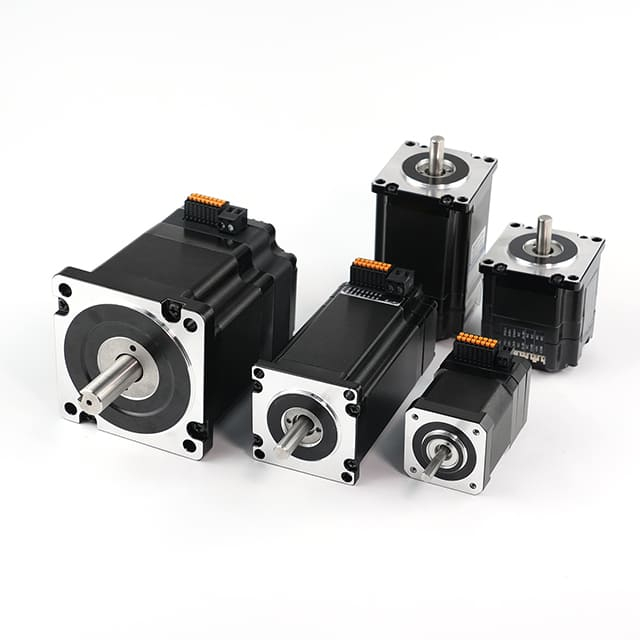
Types of Stepper Motors and Their Power Characteristics
Stepper motors come in several distinct types, each with unique construction, operation, and power characteristics. While all stepper motors function on DC power and convert electrical pulses into precise mechanical steps, their design differences determine their performance in terms of torque, speed, accuracy, and efficiency. Understanding these types helps in choosing the most suitable stepper motor for any specific application.
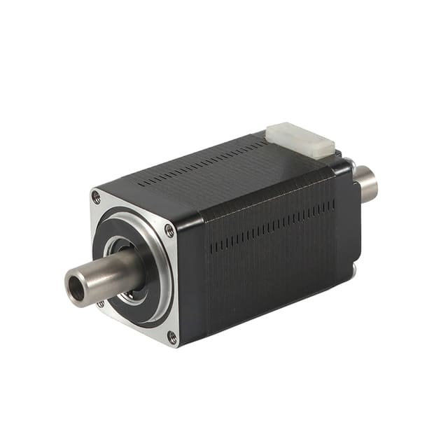
1. Permanent Magnet (PM) Stepper Motors
Permanent Magnet (PM) stepper motors are the simplest type, using a permanent magnet rotor and electromagnetic stator coils. The rotor aligns with the magnetic poles created by the stator windings as they are energized in sequence.
Power Characteristics:
Power Source: DC (typically 5V to 12V)
Current Range: 0.3A to 2A per phase
Torque Output: Low to medium, depending on size
Speed Range: Best suited for low-speed applications
Efficiency: High at low speeds, but torque drops rapidly with increasing speed
Key Features:
Smooth and stable operation at low speeds
Simple and cost-effective design
Commonly used in printers, cameras, and simple automation equipment
Summary:
PM stepper motors are ideal for low-power, precision applications where cost and simplicity matter more than speed or high torque.
2. Variable Reluctance (VR) Stepper Motors
Variable Reluctance (VR) stepper motors feature a soft iron, toothed rotor without any permanent magnets. The rotor moves by aligning itself with the stator poles that are magnetized by the current pulses. The operation is entirely based on the principle of magnetic reluctance—the rotor always seeks the lowest magnetic resistance path.
Power Characteristics:
Power Source: DC (through a driver with pulsed current control)
Voltage Range: 12V to 24V DC (typical)
Current Range: 0.5A to 3A per phase
Torque Output: Moderate
Speed Range: Moderate speeds achievable with accurate step control
Efficiency: Better at moderate speeds than PM types
Key Features:
High stepping accuracy due to fine rotor teeth
No magnetic detent torque (the rotor doesn’t resist movement when power is off)
Lower torque compared to hybrid or PM types
Summary:
VR stepper motors are used in precision instrumentation, medical devices, and light-duty positioning systems, where high step resolution is required.
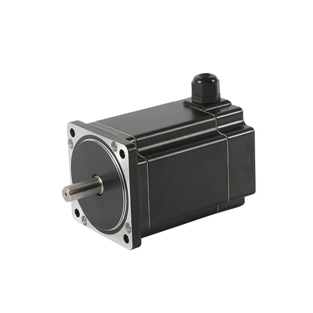
The Hybrid Stepper Motor combines the best features of both PM and VR designs. It uses a permanent magnet rotor with finely toothed structure, resulting in higher torque, better step accuracy, and smoother performance. This design allows hybrid steppers to be the most widely used type in industrial and automation applications.
Power Characteristics:
Power Source: DC (typically 12V to 48V)
Current Range: 1A to 8A per phase (depending on size)
Torque Output: High holding torque and excellent torque retention at low speeds
Speed Range: Moderate to high (though torque drops at very high speeds)
Efficiency: High when driven by microstepping drivers
Key Features:
Step angles as small as 0.9° to 1.8° per step
Smooth motion under microstepping control
High positional accuracy and reliability
Summary:
Hybrid stepper motors are used in CNC machines, robotics, 3D printers, medical pumps, and camera positioning systems, where high torque and precision are essential.
Unipolar stepper motors are defined by their winding configuration rather than rotor design. Each coil in a unipolar motor has a center tap, allowing current to flow through one half of the coil at a time. This makes driving circuitry simpler, as the current direction doesn’t need to reverse.
Power Characteristics:
Power Source: DC (5V to 24V)
Current Range: 0.5A to 2A per phase
Torque Output: Moderate (less than bipolar motors of similar size)
Efficiency: Lower due to partial coil usage per step
Key Features:
Simple and inexpensive driver design
Easier to control with microcontrollers
Lower torque compared to bipolar configuration
Summary:
Unipolar motors are ideal for low-cost applications such as hobby robotics, plotters, and educational kits, where simplicity outweighs performance.
Bipolar stepper motors have coils without center taps, meaning the current must reverse direction to change magnetic polarity. This requires a more complex driver but allows full coil utilization, resulting in greater torque and efficiency compared to unipolar designs.
Power Characteristics:
Power Source: DC (commonly 12V, 24V, or 48V)
Current Range: 1A to 6A per phase
Torque Output: High (typically 25–40% more than equivalent unipolar motors)
Efficiency: High due to complete coil energization
Key Features:
Excellent torque-to-size ratio
Smooth and powerful motion control
Requires H-bridge drivers to reverse current direction
Summary:
Bipolar stepper motors are commonly used in CNC machinery, robotics, and precision automation, where high torque and performance are essential.
A modern advancement in stepper technology, closed-loop stepper motors integrate an encoder or feedback sensor to monitor the rotor’s position in real time. The driver adjusts the current dynamically to correct any missed steps, combining the precision of stepper motors with the stability of servo systems.
Power Characteristics:
Power Source: DC (typically 24V to 80V)
Current Range: 3A to 10A per phase
Torque Output: High, with consistent torque across wider speed ranges
Efficiency: Very high, due to adaptive current control
Key Features:
No loss of steps under varying load conditions
Reduced heat generation and noise
Excellent for dynamic and high-speed applications
Summary:
Closed-loop steppers are ideal for high-performance automation, such as robotic arms, precision manufacturing, and motion control systems, where reliability and real-time correction are required.
Conclusion
Stepper motors, whether Permanent Magnet, Variable Reluctance, Hybrid, Unipolar, Bipolar, or Closed-Loop, all share the fundamental characteristic of operating on DC power. However, their power characteristics—including voltage, current, torque, and efficiency—vary significantly based on design and application.
PM and VR stepper motors excel in low-power, cost-sensitive environments.
Hybrid and Bipolar steppers dominate industrial automation due to their high torque and precision.
Closed-loop stepper motors represent the future, offering servo-like performance with stepper simplicity.
Understanding these distinctions ensures optimal selection for any project requiring accurate, repeatable, and efficient motion control.
AC-Powered Stepper Systems: A Misconception Explained
When discussing stepper motors and their power sources, a common misunderstanding arises — the idea that stepper motors can be powered directly by AC (Alternating Current). In reality, stepper motors are fundamentally DC-driven devices, even though they may sometimes appear to operate in AC-like systems. Let’s break down this misconception and explain what’s really happening inside an AC-powered stepper system.
1. The Core Principle: Stepper Motors Are DC Devices
Stepper motors operate based on discrete electrical pulses, where each pulse energizes specific stator coils to produce a magnetic field that moves the rotor by a fixed step. These pulses are controlled and sequentially applied by a driver circuit, not by continuous alternating current.
True Power Source: DC electricity (typically from 5V to 80V DC, depending on motor size)
Driver Function: Converts DC input into pulsed current signals for each motor phase
Key Concept: The “alternation” between coils is controlled switching, not sinusoidal AC power
In other words, while the motor’s phases alternate in polarity like AC, this alternation is digitally generated from a DC source.
2. Why the Misconception Exists
There are several reasons why some people mistakenly refer to stepper motors as “AC-powered”:
a. Alternating Phase Currents
Stepper motors use multiple phases (commonly two or four), and the current in these phases alternates direction to produce rotation. To an observer, this looks similar to an AC waveform — especially in bipolar stepper motors, where current reverses in each winding.
However, these are controlled current reversals, not continuous AC supplied from the mains.
b. AC Input to the Driver
Many industrial stepper systems accept AC mains input (e.g., 110V or 220V AC).
But the driver immediately rectifies and filters this AC voltage into DC power, which it then uses to generate the controlled current pulses.
So, while the system may plug into an AC outlet, the motor itself never receives AC directly.
c. Confusion with Synchronous AC Motors
Stepper motors and AC synchronous motors share similar characteristics — both have synchronous rotation with the electromagnetic field. This similarity in behavior sometimes causes confusion, even though their driving principles are entirely different.
3. What Happens Inside an “AC Stepper System”
Here’s how a typical so-called “AC stepper system” actually works:
AC Power Input:
The driver receives AC voltage from the mains (e.g., 220V AC).
AC-to-DC Conversion:
The driver’s internal power supply rectifies the AC input to DC voltage, usually with capacitors for smoothing.
Pulse Generation:
The driver’s control circuit converts this DC into a sequence of digital current pulses corresponding to the step commands.
Current Switching:
Transistors or MOSFETs inside the driver switch the current direction through the motor windings, creating magnetic fields that move the rotor step-by-step.
Rotor Motion:
The rotor follows these timed pulses, resulting in precise angular motion — the hallmark of a stepper motor.
Thus, the stepper motor is always powered by DC current, even if the system takes AC at the input.
4. Why Stepper Motors Can’t Run on Pure AC
If you were to connect a stepper motor directly to an AC power supply, it wouldn’t function correctly — and could be damaged.
Here’s why:
AC power alternates sinusoidally and uncontrollably, while stepper motors require precise timing and phase sequencing.
The rotor would vibrate or jitter, not rotate consistently.
There would be no positional control, defeating the purpose of a stepper motor.
The motor windings could overheat, as the uncontrolled current would not match the motor’s designed step sequence.
In short, AC power lacks the discrete, programmable control required for stepper operation.
5. AC Input vs. AC Operation: The Key Difference
| Aspect | AC Input Stepper System | True AC Motor System |
| Power Input | AC (converted to DC inside the driver) | AC directly powers the motor |
| Motor Type | DC-driven stepper motor | Synchronous or induction motor |
| Control Method | Pulse sequencing and microstepping | Frequency and phase control |
| Positioning Accuracy | Very high (steps per revolution) | Moderate (depends on feedback) |
| Main Use | Precision positioning | Continuous rotation or variable speed drive |
So, while stepper systems may be AC-powered at the input, their core operation is entirely DC-based.
6. Related Technologies That Blur the Line
There are advanced stepper-like technologies that further confuse the AC vs. DC distinction:
Closed-loop steppers (servo steppers):
These use feedback and sometimes sinusoidal current control that resembles AC waveforms — but still derived from DC.
Brushless DC (BLDC) motors:
They also use electronic commutation that mimics AC behavior, even though they run on DC power.
Both technologies simulate AC behavior electronically, without ever using AC mains directly for motor coils.
7. Conclusion
The term “AC-powered stepper motor” is a misconception.
While some stepper systems accept AC input, the motor itself always operates on controlled DC pulses. The AC is merely converted to DC inside the driver before powering the motor windings.
Key Takeaway:
Stepper motors are DC-driven devices that use digitally generated alternating current signals, not AC mains power.
Understanding this distinction is essential when selecting stepper systems, as it ensures proper driver compatibility, power supply design, and system reliability.
Comparing Stepper Motors with AC and DC Motors
When selecting a motor for a specific application, engineers often weigh the strengths and weaknesses of stepper motors, AC motors, and DC motors. Each type has its unique design principles, performance characteristics, and ideal use cases. Understanding their differences helps in choosing the right motor for tasks ranging from precision positioning to high-speed rotation.
1. Fundamental Operating Principles
Stepper Motors:
Stepper motors are electromechanical devices that move in discrete steps. Each pulse sent from the driver energizes the motor’s coils in sequence, producing incremental angular movement of the rotor. This allows for precise position control without requiring a feedback system.
AC Motors:
AC motors run on alternating current, where the direction of current flow periodically reverses. They rely on a rotating magnetic field created by the AC supply to induce motion in the rotor. The speed of an AC motor is directly related to the frequency of the power supply and the number of poles in the stator.
DC Motors:
DC motors operate on direct current, where current flows in one direction. The motor’s torque and speed are controlled by adjusting the supply voltage or current. Unlike stepper motors, DC motors provide continuous rotation rather than discrete steps.
2. Power Source Differences
| Motor Type | Power Type | Power Conversion Required |
| Stepper Motor | DC (controlled pulses) | AC input must be rectified to DC before use |
| AC Motor | AC (alternating current) | None (direct connection to AC mains) |
| DC Motor | DC (steady direct current) | May require a DC power supply or battery source |
Key Insight:
Even though stepper systems may plug into an AC outlet, the stepper driver always converts AC to DC before energizing the coils with precise pulse patterns.
3. Speed and Torque Characteristics
Stepper Motors:
Provide high torque at low speeds, but torque decreases as speed increases.
Ideal for low-to-moderate speed applications requiring precise motion control.
Not suitable for continuous high-speed rotation due to torque drop-off and vibration.
AC Motors:
Deliver constant torque and smooth rotation at higher speeds.
Speed is typically fixed by the supply frequency (e.g., 50 Hz or 60 Hz).
Excellent for applications needing continuous motion and high efficiency.
DC Motors:
Offer variable speed control with a simple voltage adjustment.
Produce high starting torque, making them ideal for dynamic load applications.
Require brush maintenance in brushed designs, though brushless DC (BLDC) versions solve this issue.
4. Control and Feedback Requirements
Stepper Motors:
Controlled via step and direction signals from a driver.
Can operate in open-loop mode, eliminating the need for encoders.
Position is inherently determined by the number of steps commanded.
Can use closed-loop feedback for improved torque and speed regulation.
AC Motors:
Typically require closed-loop control (using sensors) for precision.
Speed is controlled by variable frequency drives (VFDs).
Complex circuitry is needed for acceleration, braking, or reversing.
DC Motors:
Easy to control using PWM (Pulse Width Modulation) or voltage regulation.
For precision, encoders or tachometers are used in a closed-loop system.
Simple control circuits make DC motors widely used in automation and robotics.
5. Accuracy and Positioning
| Motor Type | Positioning Accuracy | Feedback Required |
| Stepper Motor | Very high (0.9°–1.8° per step typical) | Optional |
| AC Motor | Low (requires sensors for precision) | Yes |
| DC Motor | Moderate to high (depends on encoder resolution) | Usually yes |
Key Takeaway:
Stepper motors excel in open-loop positioning systems, where movement must be precise but loads are predictable. AC and DC motors need additional feedback sensors for similar accuracy.
6. Maintenance and Longevity
Stepper Motors:
Feature brushless construction, meaning minimal wear and tear.
Require virtually no maintenance under normal operation.
Can suffer from vibration or resonance if not tuned properly.
AC Motors:
Very robust and durable with long service life.
Minimal maintenance required, especially for induction types.
Bearings may need periodic lubrication or replacement.
DC Motors:
Brushed DC motors require brush and commutator maintenance.
Brushless DC motors (BLDC) are low-maintenance and long-lasting.
Suitable for environments where frequent servicing is possible.
7. Efficiency and Power Usage
Stepper Motors:
Consume power even when stationary, to maintain holding torque.
Efficiency is typically lower than that of AC or DC motors.
Best suited for applications where precision outweighs efficiency.
AC Motors:
Highly efficient, especially in three-phase induction designs.
Common in industrial machinery, HVAC systems, and pumps.
Efficiency increases with load and speed stability.
DC Motors:
Efficiency depends on design and load conditions.
BLDC motors achieve high efficiency similar to AC motors.
Widely used in battery-powered and portable systems.
8. Typical Applications
| Motor Type | Common Applications |
| Stepper Motor | 3D printers, CNC machines, robotics, camera systems, medical devices |
| AC Motor | Fans, pumps, compressors, conveyors, industrial drives |
| DC Motor | Electric vehicles, actuators, automation equipment, portable devices |
Summary Insight:
Stepper motors dominate positioning and precision tasks.
AC motors rule high-power and continuous rotation industries.
DC motors excel in variable-speed and portable applications.
9. Cost and Complexity
Stepper Motors:
Moderate cost for both motor and driver.
Simple setup for open-loop systems.
Higher cost when using closed-loop drivers.
AC Motors:
Cost-effective for high-power systems.
Require VFDs or servo controllers for variable-speed control.
Complex to implement for precise motion tasks.
DC Motors:
Low initial cost, especially for brushed types.
Simple control electronics.
Higher cost for BLDC designs with advanced controllers.
10. Conclusion: Choosing the Right Motor
Each motor type serves distinct operational goals:
Choose Stepper Motors for precision, repeatability, and controlled motion.
Choose AC Motors for continuous, efficient, and high-speed applications.
Choose DC Motors for variable-speed, dynamic-load, or portable systems.
In essence, stepper motors fill the gap between the simplicity of DC motors and the power of AC systems, providing unmatched control for automation, robotics, and CNC technologies.
Power Supply Requirements for Stepper Motors
To ensure stable performance, maximum torque, and precise control, stepper motors require properly designed and regulated power supplies. Since these motors operate based on controlled DC pulses, the quality and configuration of the power source directly affect their efficiency, speed, and overall reliability. Understanding the voltage, current, and control requirements of stepper motors is essential for designing a robust motion control system.
1. Understanding the Power Supply’s Role
The power supply provides the electrical energy needed for the stepper driver to generate current pulses that energize the motor’s windings. Unlike AC motors that can run directly from the mains, stepper motors require DC voltage to produce the magnetic fields responsible for movement.
Key responsibilities of a stepper motor power supply include:
Providing stable DC voltage to the driver
Ensuring adequate current capacity for all phases
Maintaining smooth operation during acceleration and load changes
Preventing voltage drop or ripple that can cause missed steps or overheating
2. AC vs. DC Power Sources
While AC mains power (110V or 220V) is commonly available, stepper motors cannot use AC directly. The stepper driver performs AC-to-DC conversion through rectification and filtering.
AC Input Systems:
The stepper driver receives AC input, converts it to DC internally, and outputs pulsed DC signals to the motor coils.
DC Input Systems:
Some drivers are designed for direct DC connection (e.g., 24V, 48V, or 60V DC). This configuration is common in embedded or battery-powered systems.
Conclusion:
Regardless of input type, stepper motors always operate on DC power, ensuring precise and programmable control.
3. Determining Voltage Requirements
The supply voltage affects a stepper motor’s speed and dynamic performance. Higher voltages allow faster current changes in the windings, resulting in:
However, excessive voltage can overheat the driver or motor windings. The ideal voltage is typically determined by the motor’s inductance and current rating.
General Formula (Approximation):
Recommended Voltage = 32 × √(Motor Inductance in mH)
For example, a motor with 4 mH inductance would use approximately:
32 × √4 = 64V DC.
Typical Voltage Ranges:
Small stepper motors: 5–24V DC
Medium stepper motors: 24–48V DC
Industrial stepper motors: 60–80V DC or higher
4. Current Requirements and Driver Capacity
The current rating defines the torque capability of a stepper motor. Each winding requires a specific current to generate sufficient magnetic force.
The driver regulates current precisely, even if supply voltage is higher.
The power supply must deliver total current for all active phases plus a safety margin.
Example Calculation:
If a stepper motor has a rated current of 2A per phase and operates with two phases on, the minimum power supply current should be:
2A × 2 phases = 4A total
To ensure reliability, add a 25% safety margin, giving a power supply rated at around 5A.
5. Voltage, Current, and Torque Relationship
| Parameter | Effect on Motor Performance |
| Higher Voltage | Faster step response and higher top speed |
| Higher Current | Greater torque output but more heat generation |
| Lower Voltage | Smoother motion but reduced torque at high speed |
| Insufficient Current | Missed steps and reduced holding torque |
Optimal setup: High enough voltage for speed, and current regulated to the motor’s rated value.
6. Power Supply Types for Stepper Systems
a. Linear Power Supplies:
Provide clean, low-noise DC output
Ideal for precision motion systems or low-voltage motors
Heavier and less efficient than switching types
b. Switching Power Supplies (SMPS):
Compact, lightweight, and efficient
Common in industrial and embedded stepper applications
Must be chosen with sufficient peak current handling to avoid tripping
c. Battery or Portable DC Sources:
7. Importance of Current Regulation
Stepper motors are current-driven devices, not voltage-driven. The driver ensures that each winding receives the exact rated current, regardless of supply voltage variations. Modern stepper drivers use:
Chopper control to limit current precisely
Microstepping techniques to divide steps for smoother motion
Protection features such as overcurrent and overvoltage shutdown
Because of this, the power supply voltage can be higher than the motor’s rated voltage, as long as the driver limits current correctly.
8. Managing Heat and Efficiency
Improperly sized power supplies or unregulated current can lead to:
Excessive heat buildup in windings
Driver overheating or shutdowns
Reduced efficiency and motor life
Best Practices:
Use a heat sink or fan for high-current systems
Ensure adequate ventilation for both driver and supply
Avoid operating at the maximum rated current continuously
Choose drivers with thermal protection for safety
9. Power Supply Protection Features
A reliable stepper motor power supply should include the following protections:
Overvoltage protection (OVP) – prevents damage from surges
Overcurrent protection (OCP) – limits excessive load draw
Short circuit protection (SCP) – safeguards driver circuits
Thermal shutdown – stops operation during overheating
These features enhance both motor safety and system longevity.
10. Practical Example of Power Supply Selection
Suppose you are powering a NEMA 23 stepper motor rated at:
3A per phase
3.2V coil voltage
4 mH inductance
Step 1: Estimate optimal supply voltage
32 × √4 = 64V DC
Step 2: Determine current requirement
3A × 2 phases = 6A total
Step 3: Add margin → 7.5A recommended
Step 4: Choose a 48–64V DC, 7.5A power supply (approx. 480W) with good cooling and protection features.
11. Summary: Key Takeaways
Stepper motors always operate on DC power, even if the system’s input is AC.
Choose a power supply that delivers stable DC voltage, rated above the motor’s coil voltage.
Ensure adequate current capacity to power all motor phases simultaneously.
Use regulated drivers to manage current and protect the motor.
Proper power supply design ensures maximum torque, speed stability, and motor lifespan.
Conclusion: Stepper Motors Use DC Power
In conclusion, stepper motors are DC-operated devices that rely on precisely timed pulses of DC current to achieve controlled movement. While the control signals may mimic alternating patterns, the underlying power source is always DC. When powered correctly through a suitable driver, stepper motors deliver unparalleled accuracy, repeatability, and torque control across a broad range of automation and mechatronic applications.