Servo motors are vital components in modern automation, robotics, and control systems. Their ability to deliver precise motion control, high torque density, and fast response times makes them indispensable in industries ranging from manufacturing to robotics and aerospace. Understanding how to drive a servo motor correctly is essential for achieving optimal performance, extending system life, and maintaining operational reliability.
In this detailed guide, we'll cover everything you need to know about driving servo motors—from understanding their control principles to setting up drivers, controllers, and feedback systems for smooth, accurate motion.
Understanding the Basics of Servo Motors
A servo motor is a type of electromechanical device designed to precisely control the angular or linear position, velocity, and acceleration of a mechanical system. Unlike conventional motors that rotate continuously when power is applied, a servo motor moves to a specific position and maintains it with high accuracy using a closed-loop control system.
Servo motors are widely used in robotics, CNC machinery, industrial automation, aerospace, and automotive systems, where exact movement and rapid response are critical.
What Is a Servo Motor?
A servo motor is essentially a motor with a feedback mechanism. It operates based on control signals that determine its position or speed. The control system sends a signal to the motor, which then rotates the shaft accordingly. A feedback sensor (usually an encoder or resolver) constantly measures the shaft position and sends this data back to the controller, ensuring that the actual position matches the desired command.
This feedback-based operation makes servo motors ideal for precise motion control, where accuracy and repeatability are essential.
Core Components Required to Drive a Servo Motor
A servo motor system is not just a single device—it's an integrated setup consisting of multiple components working together in harmony. Each component has a specific role in ensuring precise motion control, stable operation, and efficient energy conversion. Understanding these core components is crucial for engineers and technicians who want to drive a servo motor effectively and maintain its performance over time.
Below, we explore each essential element that makes up a servo drive system, along with its function and importance.
1. Servo Motor
The servo motor itself is the heart of the system. It converts electrical energy into rotational or linear motion. Unlike conventional motors, a servo motor operates within a closed-loop control system, which means its speed, position, and torque are continuously monitored and adjusted according to the control input.
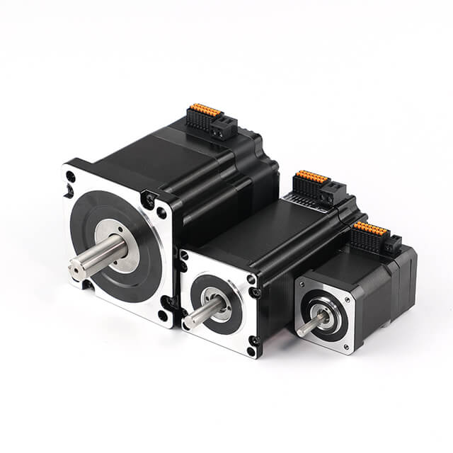
Servo motors are classified into three main types:
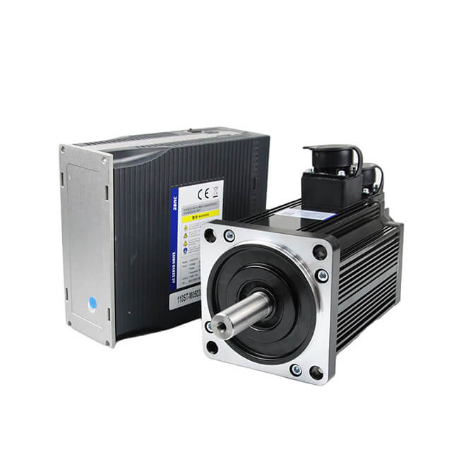
AC Servo Motors – Ideal for high-performance industrial applications requiring accuracy and torque.
DC Servo Motors – Simple, cost-effective, and used in low-power or educational setups.
Brushless DC Servo Motors (BLDC) – Offer high efficiency, low maintenance, and long operational life.
Each servo motor is designed with a rotor, stator, feedback sensor, and drive interface, forming the foundation for motion control.
2. Servo Drive (Amplifier)
The servo drive, also known as a servo amplifier, is the control center that powers and manages the motor's behavior. It receives command signals (such as desired position, velocity, or torque) from a controller and converts them into electrical signals suitable for the motor.
The servo drive also processes feedback signals from the motor's encoder or resolver, compares them with the command signal, and makes real-time corrections to maintain accurate performance.
Key functions of a servo drive include:
Regulating voltage and current supplied to the motor.
Controlling position, speed, and torque loops.
Protecting against overcurrent, overvoltage, and thermal overload.
Managing communication with the main control system (via EtherCAT, CANopen, or Modbus).
Modern servo drives are digitally programmable and can perform auto-tuning, fault diagnostics, and multi-axis synchronization for advanced automation systems.
The controller acts as the brain of the servo system. It generates motion commands that dictate how the motor should behave. Depending on the application, this could be a PLC (Programmable Logic Controller), CNC controller, or microcontroller-based motion processor.
Main roles of the controller:
Sending position, speed, or torque commands to the servo drive.
Coordinating multiple axes of motion for synchronized movement.
Executing predefined motion profiles (such as acceleration, deceleration, or interpolation).
Handling communication protocols for system integration.
For instance, in an automated production line, the controller synchronizes multiple servo motors to achieve precise timing and coordination between robotic arms or conveyor belts.
4. Feedback Device (Encoder or Resolver)
A feedback device is a critical component that ensures accuracy and stability in a servo motor system. It continuously measures the shaft's position, speed, and sometimes torque, sending this data back to the servo drive or controller.
The most common feedback devices include:
Optical Encoders – Offer high-resolution position and speed feedback using digital pulses.
Resolvers – Electromechanical sensors that provide analog feedback, known for robustness in harsh environments.
Hall Sensors – Used primarily in BLDC servo motors for basic commutation feedback.
This continuous feedback enables the system to compare the commanded position with the actual position and instantly correct any deviation, resulting in smooth, precise motion control.
5. Power Supply
A stable power supply is essential for reliable servo operation. It provides the required voltage and current to both the servo drive and motor.
Depending on the system configuration, the power supply can be:
In addition, a regulated power supply ensures consistent energy delivery and prevents electrical noise or voltage fluctuations from affecting performance. Some advanced systems include braking resistors or energy recovery circuits to manage excess regenerative energy during deceleration.
6. Communication Interface
Modern servo systems often rely on digital communication protocols for seamless integration and real-time data exchange between controllers, drives, and supervisory systems.
Common communication standards include:
EtherCAT – High-speed, deterministic network for real-time control.
CANopen – Compact protocol ideal for distributed control systems.
Modbus or RS-485 – Simple serial communication for small-scale automation.
PROFINET and Ethernet/IP – Used in large industrial networks for interoperability.
A reliable communication interface ensures synchronized multi-axis control, rapid diagnostics, and efficient data transmission throughout the automation network.
7. Cables and Connectors
Although often overlooked, high-quality cables and connectors are vital for signal integrity and safety. Servo systems typically include:
Power Cables – Supply voltage and current to the motor.
Feedback Cables – Carry encoder or resolver signals back to the controller.
Communication Cables – Transfer control and diagnostic data between system components.
Proper shielding and grounding of cables are essential to prevent electromagnetic interference (EMI) that could cause erratic motor behavior or communication errors.
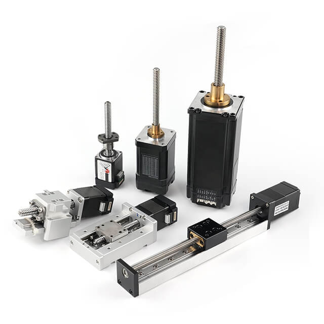
8. Mechanical Load and Coupling System
The mechanical load represents the physical system driven by the servo motor, such as a conveyor, robotic arm, or lead screw. To ensure optimal power transmission, the motor shaft is connected to the load via couplings, gears, or belts.
Design considerations include:
Load inertia matching – The motor should be properly sized to handle the load's inertia for smooth control.
Alignment – Proper shaft alignment prevents vibration and premature bearing wear.
Mounting rigidity – Ensures mechanical stability during high-speed operation.
The performance of a servo system largely depends on how efficiently torque is transmitted from the motor to the load.
9. Safety and Protection Components
Safety components protect both the servo motor and operators from hazards. These include:
Emergency Stop (E-Stop) Circuits
Limit Switches to prevent over-travel
Circuit Breakers and Fuses for electrical protection
Thermal Sensors to monitor motor temperature
Integrating these safety devices ensures compliance with industrial standards and prevents costly equipment damage.
Conclusion
Driving a servo motor effectively requires more than just connecting wires—it demands a complete, well-coordinated system of electrical, mechanical, and control components. Each element—from the servo drive and controller to the feedback device and power supply—plays a crucial role in achieving precise, responsive, and stable motion control.
By understanding and properly integrating these core components, engineers can design servo systems that deliver maximum accuracy, efficiency, and reliability for any application, from robotics to advanced manufacturing.
Principle of Operation: How a Servo Motor is Driven
A servo motor operates on the principle of closed-loop control, where the motor's position, speed, and torque are constantly monitored and adjusted to match a desired command signal. This system ensures high precision, responsiveness, and stability, making servo motors ideal for automation, robotics, CNC systems, and aerospace applications where accuracy is critical.
Understanding how a servo motor is driven requires breaking down the interaction between its electrical, mechanical, and feedback components. Each element works together in real-time to produce smooth and controlled motion.
At the heart of every servo system lies the closed-loop feedback mechanism. Unlike open-loop systems (such as standard DC or stepper motors), a servo motor constantly compares the commanded position or speed with the actual output measured by a feedback sensor.
When any difference or error is detected between the desired and actual positions, the system automatically corrects it by adjusting voltage, current, or torque—ensuring continuous accuracy and stability under variable loads.
This dynamic self-correction process is what gives servo motors their superior precision and reliability.
2. Core Control Loops in Servo Systems
Servo drives use a three-loop control system, which regulates torque, speed, and position in a sequential manner. These loops are processed continuously at high speed to maintain accurate motion control.
(a) Current (Torque) Control Loop
This is the innermost loop, responsible for controlling the current supplied to the motor windings, which directly determines the output torque.
The servo drive adjusts the motor current in response to torque demands, ensuring instant reaction to load variations.
It provides a fast, stable foundation for the higher control loops.
The speed loop uses the feedback from the motor's encoder to regulate the rotational velocity.
The drive compares the commanded speed signal with the actual speed, and the error is processed to generate the necessary torque command.
This loop ensures the motor maintains a constant speed, even under changing mechanical loads.
(c) Position Control Loop
The outermost loop ensures the motor shaft reaches and maintains the target position accurately.
It compares the target position (set by the controller) with the feedback signal from the encoder.
Any deviation generates a correction signal that adjusts the motor's speed or torque until the exact position is reached.
Together, these loops form a hierarchical system where the position loop controls speed, and the speed loop controls torque, resulting in precise, stable, and responsive motion control.
3. Step-by-Step Operation of a Servo Motor
Here's a simplified breakdown of how a servo motor is driven from command to motion:
Command Signal Input:
The controller (PLC, CNC, or microcontroller) sends a signal to the servo drive, representing the desired position, speed, or torque.
Signal Processing by Servo Drive:
Motor Rotation:
Feedback Measurement:
The encoder or resolver attached to the motor shaft continuously monitors its position and speed.
This feedback data is sent back to the servo drive or controller for comparison with the command input.
Error Detection and Correction:
If a discrepancy (error) is detected between the command and actual output, the drive instantly compensates by adjusting current or voltage.
This rapid correction maintains accuracy and prevents overshoot or oscillation.
Stable Output Achieved:
This constant feedback and correction cycle happens thousands of times per second, providing smooth and reliable motion in all operating conditions.
4. Signal Types Used to Drive Servo Motors
Servo drives accept different types of control signals, depending on the application and controller used:
Analog Signals (±10V):
Used for speed and torque control, where voltage amplitude represents command magnitude.
Pulse Train Signals (PWM or Pulse-Direction):
Commonly used in CNC and robotics to represent position and velocity.
Digital Communication Signals (EtherCAT, CANopen, Modbus):
Provide real-time, high-speed motion control and feedback synchronization across multiple axes.
These communication methods allow the servo system to function as part of a smart, networked control environment.
5. Role of PID Control in Servo Systems
To maintain precise control, servo drives use PID (Proportional-Integral-Derivative) algorithms that continuously minimize errors between the target and actual values.
Proportional Control (P): Responds to the size of the error; higher values mean stronger corrections.
Integral Control (I): Eliminates long-term, accumulated errors by considering past deviations.
Derivative Control (D): Predicts and counters future errors based on the rate of change.
Fine-tuning these PID parameters is essential for achieving optimal performance—ensuring that the servo motor responds quickly but without overshoot, vibration, or instability.
6. Power Flow in a Servo System
The power flow from the electrical source to mechanical output follows this sequence:
Power Supply → Servo Drive: Provides AC or DC electrical energy.
Servo Drive → Servo Motor: Converts control signals into precise voltage and current waveforms for motor operation.
Servo Motor → Mechanical Load: Converts electrical power into mechanical torque and motion.
Feedback Device → Controller: Sends real-time position and speed data for system correction.
This energy and information exchange loop ensures high-performance motion control, regardless of system complexity or external disturbances.
7. Dynamic Response and Stability
One of the most impressive features of a servo system is its dynamic response—the ability to react almost instantaneously to changes in load or command.
When the load increases, the motor automatically increases torque output.
When the command changes, it accelerates or decelerates smoothly to the new target.
If external forces disturb the position, the control loop corrects the error immediately.
This rapid adaptability ensures consistent performance, accuracy, and repeatability, even in demanding industrial environments.
8. Practical Example of Servo Motor Operation
Consider a robotic arm controlled by servo motors:
Each joint is powered by a servo motor connected to a feedback encoder.
The motion controller sends position commands to each servo drive.
The drives adjust motor currents to reach the exact angles needed for coordinated movement.
Feedback ensures all joints stop precisely at the correct position.
This synchronization is what allows robots to perform complex, fluid, and repeatable movements in real time.
Conclusion
The operation of a servo motor is a sophisticated process based on real-time feedback, precise control loops, and rapid correction mechanisms. By continuously monitoring and adjusting its output, the servo motor achieves unmatched accuracy, torque control, and speed regulation.
Whether driving a robot, CNC machine, or automated production line, understanding the principle of operation allows engineers to optimize performance, minimize errors, and ensure long-term reliability.
Steps to Drive a Servo Motor Correctly
Driving a servo motor correctly requires more than just connecting wires and applying power. It involves precise setup, tuning, and synchronization between the motor, drive, controller, and feedback systems. A well-configured servo system ensures smooth motion, high accuracy, and reliable performance, while improper setup can cause vibration, overshoot, or even equipment damage.
Below is a step-by-step guide explaining how to drive a servo motor properly, from system identification to final calibration and testing.
1. Identify the Servo Motor Specifications
Before starting, you must fully understand the technical specifications of your servo motor. This ensures compatibility with the servo drive and control system.
Key parameters to verify include:
Rated voltage and current
Rated torque and speed
Encoder or resolver type (feedback system)
Communication protocol compatibility
Wiring diagram and pin configuration
Using incorrect ratings or incompatible feedback devices can lead to performance issues or permanent motor damage. Always refer to the manufacturer's datasheet before making any connections.
2. Select a Suitable Servo Drive
The servo drive (also known as a servo amplifier) is responsible for converting the control signals from your controller into the precise voltage and current levels needed to drive the motor.
When selecting a servo drive, ensure it matches:
The motor voltage and current ratings
The control mode you intend to use (position, velocity, or torque)
The feedback type (encoder or resolver)
The communication interface (EtherCAT, CANopen, Modbus, etc.)
Many modern drives support auto-tuning and multi-axis synchronization, making setup easier and performance more stable.
3. Connect the Power Supply
Connect a reliable and regulated power supply to the servo drive. The type of supply depends on your system:
DC supply for small servo systems (robotic arms, educational projects).
AC supply for industrial servo systems (CNC machines, conveyors).
Ensure:
Proper grounding of all components.
The correct voltage polarity and current capacity.
Adequate circuit protection (fuses, breakers, or surge suppressors).
A stable power source is critical for consistent servo performance and to prevent unexpected resets or faults.
4. Connect the Feedback Device (Encoder or Resolver)
Feedback is what makes a servo system closed-loop. The encoder or resolver provides the motor's position and speed data to the drive, allowing it to make real-time adjustments.
Follow these steps:
Connect the encoder or resolver cables to the servo drive according to the manufacturer's pinout.
Ensure the feedback lines are shielded to minimize electrical noise.
Verify correct signal polarity and wiring order to prevent misreadings.
After connection, check that the feedback signal is detected correctly by the drive before proceeding.
5. Configure the Control Signal
The control signal tells the servo what to do — whether to rotate at a certain speed, move to a specific position, or apply a given torque.
There are several types of control signals, depending on your system setup:
Analog signals (0–10V or ±10V): Used for simple speed or torque control.
Pulse (PWM or Pulse-Direction): Common in CNC and motion control systems for position commands.
Digital communication protocols (EtherCAT, CANopen, Modbus): For advanced multi-axis synchronization and monitoring.
Properly configure the signal type in the servo drive settings to match the output format of your controller.
6. Tune the PID Control Parameters
Once the system is connected, it's time to tune the control loops. Servo drives use PID (Proportional, Integral, Derivative) algorithms to maintain stable operation.
Tuning ensures:
Quick response without overshooting.
Stable operation without oscillations.
Accurate tracking of command signals.
Methods for PID tuning:
Manual tuning: Adjust P, I, and D values gradually while observing system behavior.
Auto-tuning: Many modern drives include automatic tuning that optimizes parameters based on load and inertia.
A well-tuned system will respond smoothly to changes in command and load, maintaining consistent performance even under dynamic conditions.
7. Set Motion Parameters
Define motion profiles and operational limits within the drive or controller:
These parameters ensure the servo motor operates safely within its mechanical and electrical limits. For applications like robotic arms or CNC axes, motion profiles should be optimized for both efficiency and precision.
8. Perform Initial Testing and Verification
Before integrating the servo into a full system, perform initial test runs at low speed and no load to ensure everything functions correctly.
Check for:
Correct motor rotation direction.
Smooth and stable motion.
Accurate feedback readings.
No unusual noise, vibration, or overheating.
Gradually increase speed and load while monitoring current draw, torque response, and temperature. If any instability or oscillation occurs, recheck tuning or wiring.
9. Implement Safety and Protection Mechanisms
Servo motors can generate high torque and speed, so safety precautions are essential. Include:
Emergency stop (E-Stop) circuits
Limit switches to prevent over-travel
Braking resistors for controlled deceleration
Overcurrent, overvoltage, and thermal protection
Additionally, ensure all equipment complies with relevant industrial safety standards before deployment.
10. Integrate with the Control System
Once the servo system is tested and stable, integrate it into your main control architecture — such as a PLC, CNC controller, or motion control network.
Set communication parameters and addresses for digital protocols.
Synchronize multi-axis systems if required.
Program movement sequences and logic in your control software.
Proper integration ensures coordinated motion, improved diagnostics, and real-time monitoring for performance optimization.
11. Final Calibration and Maintenance
After installation, perform a final calibration to fine-tune positioning accuracy and system responsiveness. Verify that all motion commands correspond precisely to real-world positions.
Regular maintenance checks should include:
Inspecting cables and connectors for wear.
Checking encoder alignment and cleanliness.
Monitoring motor temperature and noise levels.
Backing up parameter settings for quick recovery.
Routine maintenance ensures long-term reliability and prevents costly downtime.
Conclusion
Driving a servo motor correctly involves a methodical approach that covers electrical setup, signal configuration, PID tuning, and safety measures. Every stage — from power connection to system calibration — plays a crucial role in ensuring smooth, accurate, and efficient operation.
By following these structured steps, you can build a servo system that delivers exceptional precision, stability, and performance, whether for industrial automation, robotics, or advanced motion control applications.
Driving Servo Motors Using Microcontrollers and PLCs
Servo motors are at the heart of modern motion control systems, providing precise position, speed, and torque control across industries — from robotics to manufacturing automation. To operate effectively, servo motors require a control system that interprets commands, processes feedback, and adjusts motor behavior in real-time. Two of the most widely used control platforms for this purpose are microcontrollers and Programmable Logic Controllers (PLCs).
In this article, we will explore in depth how to drive servo motors using microcontrollers and PLCs, discussing their architectures, interfacing methods, communication protocols, and best practices for efficient control.
1. Overview: Servo Motor Control Systems
A servo control system consists of three main components:
Controller – The brain that sends position, speed, or torque commands.
Servo Drive (Amplifier) – Converts control signals into power suitable for the motor.
Servo Motor – Executes the motion based on drive output and sends feedback to the controller.
Microcontrollers and PLCs serve as the controller, generating the control signals (such as PWM, analog, or digital commands) that the servo drive interprets to regulate motor motion.
2. Driving Servo Motors with Microcontrollers
2.1 What is a Microcontroller?
A microcontroller (MCU) is a compact, programmable chip that contains a processor, memory, and input/output interfaces on a single integrated circuit. Popular examples include Arduino, STM32, PIC, and ESP32.
Microcontrollers are ideal for servo control in low- to mid-level automation systems, especially in robotics, drones, mechatronics, and embedded systems where cost efficiency and customization are essential.
2.2 Control Signal Generation
Servo motors are typically controlled via Pulse Width Modulation (PWM) or digital communication.
PWM Control: The MCU outputs a square wave where the pulse width determines the servo's position or speed.
Analog or Digital Control: Some advanced MCUs use DAC (Digital-to-Analog Converters) or serial communication (UART, I⊃2;C, SPI, CAN) to send precise digital commands to the drive.
For example, a standard RC servo accepts a PWM signal of 50 Hz (20 ms period), where:
Industrial servo systems often require higher-frequency PWM or pulse/direction signals generated through dedicated MCU timers for greater precision.
2.3 Feedback Processing
Feedback from the servo's encoder or potentiometer allows the MCU to verify actual motor position or speed.
Common feedback integration methods include:
Quadrature encoder interface (QEI) modules in MCUs to decode encoder signals.
Analog input reading for position sensors.
Digital counters for pulse feedback.
By comparing command and feedback data, the MCU executes PID algorithms to minimize error, enabling closed-loop control.
2.4 Example: Arduino-Based Servo Control
A basic servo control setup using Arduino includes:
Servo motor connected to PWM pin.
Power supply shared between motor and Arduino ground.
Software using the Servo.h library to generate control pulses.
For industrial-grade applications, advanced microcontrollers (like STM32 or TI C2000 series) can perform real-time PID control, PWM synchronization, and communication with servo drives via CANopen or EtherCAT.
3. Driving Servo Motors with PLCs
3.1 What is a PLC?
A Programmable Logic Controller (PLC) is an industrial-grade computer used for automation and process control. PLCs are more robust than microcontrollers, featuring rugged I/O modules, real-time operation, and reliable communication with industrial networks.
They are the preferred choice for factory automation, conveyors, CNC machines, and robotics where multiple servos must operate in coordination.
3.2 Servo Control Architecture in PLC Systems
In a PLC-based servo control system, the PLC acts as the motion controller, sending commands to the servo drive, which in turn drives the servo motor. Feedback from the encoder is fed back either to the drive or directly to the PLC for monitoring.
Typical control modes include:
Pulse and Direction Control – PLC sends pulses for movement and direction signals.
Analog Control (0–10V or ±10V) – Used for speed or torque commands.
Fieldbus Communication (EtherCAT, PROFIBUS, CANopen, Modbus TCP) – Used in modern PLCs for high-speed data exchange and multi-axis synchronization.
3.3 PLC Programming for Servo Control
Servo control logic in PLCs is developed using Ladder Diagram (LD), Structured Text (ST), or Function Block Diagram (FBD) languages.
Example workflow:
Configure servo drive parameters via manufacturer software.
Set PLC output module type (pulse or analog).
Define motion parameters — acceleration, deceleration, target position.
Write motion commands using motion control function blocks, such as:
MC_Power() – Enable the servo drive
MC_MoveAbsolute() – Move to specific position
MC_MoveVelocity() – Continuous speed control
MC_Stop() – Controlled deceleration stop
For example, a Siemens or Mitsubishi PLC can control servo drives via EtherCAT or SSCNET networks, allowing synchronized multi-axis motion in robotic arms or pick-and-place systems.
3.4 Feedback and Monitoring
PLCs constantly monitor feedback from servo systems to ensure precise operation. Feedback signals can include:
Encoder pulses for position and speed verification.
Alarm signals for overcurrent, overload, or position errors.
Drive status flags for diagnostics.
Modern PLCs support real-time monitoring dashboards, allowing operators to visualize speed, torque, and error status, ensuring safe and efficient operation.
4. Comparison: Microcontroller vs. PLC in Servo Control
| Feature | Microcontroller (MCU) | Programmable Logic Controller (PLC) |
| Application Scale | Small-scale, embedded systems | Industrial automation, multi-axis control |
| Programming | C/C++, Arduino IDE, Embedded C | Ladder Logic, Structured Text |
| Control Precision | High for single-axis | High for coordinated multi-axis |
| Cost | Low | Moderate to high |
| Reliability | Moderate (depends on design) | High (industrial-grade) |
| Networking | Limited (UART, I⊃2;C, SPI, CAN) | Extensive (EtherCAT, PROFINET, Modbus TCP) |
| Flexibility | Very customizable | Highly modular but structured |
Microcontrollers are best for compact, custom-built systems with fewer motors, while PLCs excel in large-scale, synchronized industrial applications.
5. Best Practices for Driving Servo Motors
Match voltage and current ratings between motor, drive, and controller.
Ensure proper grounding to reduce electrical noise.
Use shielded cables for encoder and communication lines.
Implement PID tuning for stable closed-loop control.
Integrate safety features such as E-stop, torque limit, and overcurrent protection.
Regularly calibrate encoders and drives for long-term accuracy.
6. Conclusion
Driving servo motors using microcontrollers and PLCs offers flexible options for precise motion control, depending on your application scale and complexity.
Microcontrollers provide low-cost, customizable control for smaller systems and prototypes.
PLCs, on the other hand, deliver robust, synchronized performance ideal for industrial automation and multi-axis coordination.
Understanding the strengths of each approach enables engineers to design servo systems that balance performance, cost, and reliability, achieving the highest level of motion precision and control.
Troubleshooting Common Servo Motor Driving Issues
Servo motors are essential components in precision motion control systems, widely used in robotics, CNC machinery, conveyors, and automated production lines. While servo systems offer high accuracy, fast response, and stability, they can occasionally face operational issues due to improper setup, wiring errors, mechanical faults, or parameter misconfigurations.
This comprehensive guide will help you identify, diagnose, and resolve common servo motor driving problems, ensuring maximum performance and system reliability.
1. Overview: Why Servo Motors Malfunction
Servo systems are closed-loop mechanisms that rely on continuous feedback between the motor, drive, and controller. Any disruption in this feedback or in the control loop can cause instability, unexpected motion, or system shutdown.
Typical causes include:
Incorrect wiring or grounding.
Faulty feedback signals from encoders or resolvers.
Poorly tuned control parameters.
Overload or overheating.
Communication errors between drive and controller.
A methodical troubleshooting approach can pinpoint these problems efficiently.
2. Motor Does Not Start or Respond
Possible Causes:
Power supply not connected or insufficient voltage.
Servo drive not enabled or in fault condition.
Incorrect wiring between the drive and motor.
Command signal not received by the drive.
Solutions:
Check power supply connections — Verify that the supply voltage matches the servo drive's specifications and ensure proper grounding.
Enable the drive — Most drives have an enable input that must be activated via PLC, microcontroller, or manual switch.
Check command input — Confirm that the control signal (PWM, pulse, analog voltage, or communication command) is being transmitted correctly.
Inspect fault indicators — Many servo drives feature LED codes or display messages; refer to the manufacturer's manual for interpretation.
If the drive does not power up, test input fuses, relays, and emergency-stop circuits for continuity.
3. Servo Motor Vibrates or Oscillates
Possible Causes:
Improper PID tuning parameters.
Mechanical resonance or backlash in the load.
Loose couplings or mounting bolts.
Electrical noise in feedback lines.
Solutions:
Adjust PID control gains — Excessive proportional gain can cause oscillation. Start with default values and fine-tune gradually.
Perform mechanical inspection — Tighten all screws, couplings, and check for worn-out bearings or belts.
Use vibration damping filters — Some servo drives have notch filters or resonance suppression features.
Shield feedback cables — Use shielded twisted-pair cables for encoder or resolver signals and connect shielding to ground properly.
Vibration can often be minimized by matching the system's load inertia to the motor's rated inertia.
4. Inaccurate Positioning or Drift
Possible Causes:
Encoder misalignment or damaged feedback signal.
Incorrect scaling of feedback pulses.
Mechanical backlash or slippage.
PID parameters not optimized.
Solutions:
Inspect encoder connections — Ensure proper wiring and no signal interference. Use an oscilloscope to check encoder waveform quality.
Recalibrate feedback system — Verify encoder counts per revolution (CPR) and resolution settings in the drive.
Eliminate backlash — Replace worn gears or couplings.
Tune control loop — Refine PID settings to improve position accuracy and eliminate steady-state errors.
Position drift can also occur if electrical noise causes false encoder pulses; adding ferrite cores or grounding improvements can help.
5. Overheating of the Servo Motor
Possible Causes:
Continuous overloading or high torque demand.
Insufficient cooling or poor ventilation.
Excessive current draw due to drive misconfiguration.
Motor running below rated speed with high torque.
Solutions:
Monitor current consumption — Check drive diagnostics for real-time current draw.
Reduce load — Ensure the motor operates within its rated torque and duty cycle.
Improve cooling — Install fans or heatsinks to enhance airflow around the motor.
Verify tuning — Improper PID settings can cause the motor to draw excessive current even at steady-state operation.
Persistent overheating may damage winding insulation, leading to irreversible motor failure — therefore, temperature monitoring is essential.
6. Servo Drive Fault or Alarm Triggers
Possible Causes:
Overvoltage, overcurrent, or under-voltage faults.
Encoder signal loss or mismatch.
Communication timeout with controller.
Excessive regenerative energy during braking.
Solutions:
Check fault code or alarm log — Identify the exact error type from the drive's display or software interface.
Inspect wiring and connectors — Ensure all terminal screws are tight and no loose connections exist.
Install braking resistor — Absorbs excess regenerative energy during deceleration.
Verify grounding — Poor grounding can cause false alarms or communication dropouts.
Modern servo drives offer diagnostic tools that allow monitoring of fault histories, which can significantly speed up troubleshooting.
7. Jerky or Unstable Motion
Possible Causes:
Noise in command or feedback signal.
Incorrect acceleration/deceleration profile.
Load imbalance or misalignment.
Timing mismatch between multiple axes.
Solutions:
Check input signal stability — Use an oscilloscope to verify clean PWM or analog signals.
Smooth motion profile — Increase acceleration and deceleration times to reduce mechanical shock.
Align mechanical load — Misaligned couplings can cause irregular torque transmission.
Synchronize multi-axis systems — Use proper synchronization protocols such as EtherCAT or CANopen for coordinated motion.
Jerky motion often indicates feedback delays or control loop instability, requiring careful tuning of servo parameters.
8. Communication and Signal Interference Issues
Possible Causes:
Faulty communication cables or connectors.
Incompatible baud rate or protocol configuration.
Electrical noise in communication lines.
Ground loops between devices.
Solutions:
Verify communication settings — Ensure baud rate, data bits, and parity match between servo drive and controller.
Use shielded and twisted cables — Especially for long-distance communication lines (RS-485, CAN, EtherCAT).
Isolate power and signal grounds — Prevent ground loops by connecting only one end of the shield to the ground.
Add ferrite cores — Helps suppress high-frequency noise.
Stable communication ensures consistent servo command execution and prevents unpredictable behavior in synchronized motion systems.
9. Excessive Noise or Unusual Sound
Possible Causes:
Mechanical friction or misalignment.
Bearing wear or insufficient lubrication.
Resonance at specific frequencies.
High-frequency electrical noise.
Solutions:
Inspect bearings and couplings — Replace damaged components.
Ensure proper alignment between motor shaft and load.
Apply damping filters or adjust speed profiles to avoid resonance frequencies.
Check grounding and shielding to minimize electrical interference noise.
Continuous noise during operation should never be ignored—it often signals early mechanical or electrical degradation.
10. Preventive Maintenance Tips
To minimize recurring issues, implement these preventive practices:
Perform regular inspection of cables, connectors, and mounting bolts.
Keep the servo motor clean and dust-free.
Log and analyze drive alarms periodically.
Back up all servo drive parameters and tuning data.
Use environmentally appropriate enclosures to protect from moisture and vibration.
Routine maintenance not only prevents failures but also enhances long-term servo system accuracy and reliability.
11. Conclusion
Effective troubleshooting of servo motor driving issues requires a clear understanding of electrical, mechanical, and control system interactions. By systematically analyzing symptoms, checking wiring, adjusting parameters, and monitoring feedback signals, engineers can quickly restore system stability and optimize performance.
A properly configured and maintained servo system delivers precise, smooth, and efficient motion, enabling consistent productivity across industrial and automation applications.
Safety Precautions When Driving Servo Motors
Servo motors are vital in modern automation, robotics, CNC machines, and industrial control systems. Their high torque, precision, and responsiveness make them ideal for complex motion applications. However, these same characteristics also make servo systems potentially dangerous when handled improperly. To ensure safe operation, installation, and maintenance, it is crucial to follow specific safety precautions when driving servo motors.
This guide provides a detailed overview of best practices and safety measures to protect both personnel and equipment while ensuring reliable servo system performance.
1. Understanding the Importance of Safety in Servo Systems
Servo systems operate with high voltage, high speed, and dynamic motion, which can pose serious risks if not properly managed. Common hazards include electric shock, mechanical injury, burns, or unexpected motion.
Proper safety practices help to:
Prevent accidents and injuries.
Protect sensitive electronic components.
Extend motor and drive lifespan.
Maintain compliance with industrial safety standards (e.g., IEC, ISO, OSHA).
2. Electrical Safety Measures
2.1 Verify Power Supply Compatibility
Before powering up the system, always check the rated voltage and current of both the servo motor and servo drive.
Never exceed the rated input voltage.
Ensure correct AC or DC power type as per the manufacturer's specification.
Use isolated power supplies for control and motor power to prevent ground faults.
2.2 Proper Grounding
Improper grounding can lead to electric shock, noise interference, or equipment malfunction.
Ground all servo drives, controllers, and motor housings securely to a common earth point.
Use thick, low-impedance wires for grounding.
Avoid creating ground loops by grounding shields only at one end.
2.3 Disconnect Power Before Maintenance
Always turn off and isolate the main power supply before:
Connecting or disconnecting servo cables.
Modifying wiring or adjusting parameters.
Performing mechanical work on the motor shaft or load.
Wait several minutes after shutdown — many servo drives contain high-voltage capacitors that remain charged even after power-off. Check the discharge indicator LED before touching internal components.
3. Mechanical Safety Precautions
3.1 Secure Mounting
Servo motors can generate significant torque. Ensure that the motor and its load are securely mounted using the correct bolts and alignment tools.
Use vibration-resistant fasteners.
Avoid over-tightening, which may damage bearings or misalign couplings.
Confirm shaft alignment between motor and driven load to prevent stress and mechanical wear.
3.2 Avoid Contact with Moving Parts
When powered, servo motors can start suddenly.
Keep hands, hair, tools, and loose clothing away from the motor shaft or coupling.
Use guards or covers to protect operators from rotating components.
Never attempt to stop the motor by hand.
3.3 Use Proper Couplings
Use couplings designed to handle the torque and speed of your servo motor.
Avoid rigid couplings for misaligned shafts.
Check for wear and replace couplings periodically.
Improper coupling can cause vibration, noise, or mechanical failure.
4. Environmental Safety Considerations
4.1 Maintain Proper Ventilation
Servo motors and drives produce heat during operation.
Install in well-ventilated areas with adequate air circulation.
Keep cooling fans, heatsinks, and vents free from dust or obstructions.
Avoid enclosing drives in tightly sealed boxes without forced ventilation.
4.2 Avoid Contaminants
Keep servo systems away from moisture, oil, metal dust, and corrosive gases.
Contaminants can cause short circuits or insulation degradation.
If necessary, use IP-rated enclosures for harsh industrial environments.
4.3 Temperature Control
Servo performance can degrade at high temperatures.
Maintain ambient temperature within the drive's rated range (typically 0°C to 40°C).
Avoid placing drives near heat sources.
Consider installing temperature sensors for continuous monitoring.
5. Operational Safety During Start-Up
5.1 Initial Testing
When testing or commissioning a servo motor:
Start at low speed and low torque.
Run without load initially to verify direction, feedback, and stability.
Monitor temperature, vibration, and current draw before increasing load.
5.2 Emergency Stop (E-Stop) System
Install a dedicated emergency stop button within easy reach of operators.
Ensure the E-stop directly cuts power to the motor and disables the drive.
Test the E-stop regularly to verify its function.
Comply with industrial safety standards like ISO 13850 for emergency stop systems.
5.3 Controlled Start and Stop
Avoid sudden starts and stops, as these can stress both mechanical and electrical components.
6. Feedback and Signal Safety
6.1 Protect Encoder and Feedback Lines
Encoders provide vital position and speed data. Damage or interference can cause erratic motion or system failure.
Use shielded cables for encoder connections.
Keep feedback lines separate from high-power cables.
Ensure secure connector locking to prevent signal loss during vibration.
6.2 Check Signal Integrity
Verify that feedback signals (e.g., A/B/Z pulses or serial data) are received correctly.
Inspect for noise distortion or missing pulses.
If interference occurs, install ferrite cores or filters on communication lines.
7. Software and Parameter Safety
7.1 Verify Configuration Settings
Before enabling the drive:
Double-check all parameter settings such as motor type, encoder resolution, current limits, and control mode.
Incorrect configurations may cause uncontrolled motion.
7.2 Limit Torque, Speed, and Position
Always define safe operating limits within the drive software:
Torque limits prevent mechanical overload.
Speed limits avoid overshooting or runaway conditions.
Soft position limits protect against collision with physical stops.
7.3 Enable Fault and Alarm Monitoring
Activate fault detection features to stop operation automatically when errors occur.
Common alarms include:
8. Personal Protective Equipment (PPE)
Operators and maintenance personnel should wear:
Insulated gloves when handling electrical components.
Safety goggles to protect against debris.
Protective footwear to prevent injury from heavy equipment.
Hearing protection in noisy environments.
Never work on live systems without proper PPE and safety training.
9. Regular Maintenance and Inspection
A proactive maintenance schedule ensures safe long-term performance.
Inspect wiring, connectors, and terminal blocks regularly.
Clean accumulated dust from drives and motors.
Check for loose bolts, worn couplings, or misaligned shafts.
Record operating temperatures and vibration levels.
Routine checks can prevent sudden breakdowns and extend the service life of the entire servo system.
10. Compliance with Safety Standards
Ensure your servo motor setup complies with relevant international safety standards, including:
IEC 60204-1: Electrical equipment safety for machinery.
ISO 12100: Risk assessment for machine safety.
UL and CE certifications: Electrical safety compliance.
Following these standards guarantees that your system meets regulatory and workplace safety requirements.
11. Conclusion
Driving a servo motor safely requires careful attention to electrical, mechanical, and environmental precautions. From ensuring proper wiring and grounding to implementing E-stop systems and maintaining clean operating conditions, each safety step contributes to reliable and hazard-free operation.
By following these guidelines, engineers and technicians can operate servo systems with confidence, reducing downtime, preventing injury, and ensuring optimal performance for years to come.
Conclusion: Mastering the Art of Driving Servo Motors
Driving a servo motor efficiently requires a deep understanding of control systems, electrical interfacing, and feedback tuning. Whether controlled via a simple PWM signal or a sophisticated multi-axis motion network, the fundamentals remain the same: precise command, accurate feedback, and dynamic correction.
By following the steps and principles outlined in this guide, engineers and technicians can achieve smooth, stable, and responsive motion control, maximizing the potential of servo motor technology in any application.