- To Share:

- |


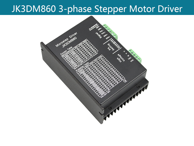
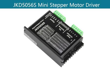
JK3DM860 Nema 34 3 Phase Stepper Motor Driver
Product Description:
Main features:
Product Type: Nema 34 3 Phase Stepper Motor Driver
Feature summary:High-performance, low price, micro-step, Automatic idle-current reduction, Optical isolating signals I/O, Max response frequency up to 200Kpps, Low temperature rise, smooth motion, Online adaptive PID technology.
Place of Origin:china
Minimum order quantity:10pcs
Support Motor: Nema 34 3 Phase Stepper Motor
Packing:The sample is packed in carton,the batch with plastic pallet
Delivery time:Standard product: 7-10days
Customized product: 25-30days
Transaction mode:EXW, FOB, FCA, CIF, FAS, CFR, CPT, CIP, DAF, DEQ, DDU, DDP...
Product Overview:
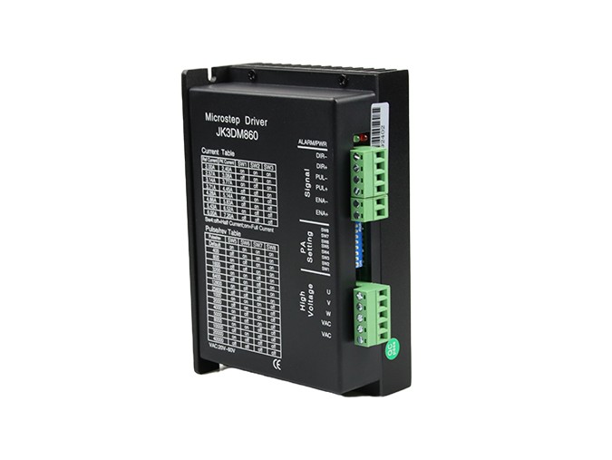
The JK3DM860 is a new generation high-performance digital stepper driver based on DSP with advanced control algorithm. The motors driven by JK3DM860 can run with much smaller noise and much less vibration than other drivers in the market. The JK3DM860 possess the feature of lower noise, lower vibration, and lower heating. The JK3DM860’s voltage is AC 24V-60V. It is suitable for all the 3-phase hybrid stepper motor whose current is less than 6.0A. There are 16 kinds of microstep of JK3DM860. The maximum step number of JK3DM860 is 40000 steps/rev. Its current range is 2.4A-7.2A, and its output current has 8 stalls. JK3DM860 has automatic semi-flow, over-voltage, under voltage and over-current protection function.
Current selection:
REF | Peak | SW1 | SW2 | SW3 |
2.00A | 2.40A | ON | ON | ON |
2.57A | 3.08A | OFF | ON | ON |
3.14A | 3.77A | ON | OFF | ON |
3.71A | 4.45A | OFF | OFF | ON |
4.28A | 5.14A | ON | ON | OFF |
4.86A | 5.83A | OFF | ON | OFF |
5.43A | 6.52A | ON | OFF | OFF |
6.00A | 7.20A | OFF | OFF | OFF |
Microstep selection:
Pulse/REV | SW5 | SW6 | SW7 | SW8 |
Default | ON | ON | ON | ON |
400 | OFF | ON | ON | ON |
800 | ON | OFF | ON | ON |
1600 | OFF | OFF | ON | ON |
3200 | ON | ON | OFF | ON |
6400 | OFF | ON | OFF | ON |
12800 | ON | OFF | OFF | ON |
25600 | OFF | OFF | OFF | ON |
1000 | ON | ON | ON | OFF |
2000 | OFF | ON | ON | OFF |
4000 | ON | OFF | ON | OFF |
5000 | OFF | OFF | ON | OFF |
8000 | ON | ON | OFF | OFF |
10000 | OFF | ON | OFF | OFF |
20000 | ON | OFF | OFF | OFF |
40000 | OFF | OFF | OFF | OFF |
Default: The pulse can be customized according to customers’ requirements.
Common indicator:
Phenomenon | Reason | Solution |
The red indicator is on. | 1. A short circuit of motor wires. | Inspect or change wires |
2. The external voltage is over or low than the driver’s working voltage. | Adjust the voltage to a reasonable rang | |
3. Unknown reason | Return the goods |
Driver functions descriptions:
Driver function | Operating instructions |
Output current setting | Users can set the driver output current by SW1-SW3 three switches. The setting of the specific output current, please refer to the instructions of the driver panel figure. |
Microstep setting | Users can set the driver Microstep by the SW5-SW8 four switches. The setting of the specific Microstep subdivision, please refer to the instructions of the driver panel figure. |
Automatic half current function | Users can set the driver half flow function by SW4. "OFF" indicates the quiescent current is set to half of the dynamic current, that is to say, 0.5 seconds after the cessation of the pulse, current reduce to about half automatically. "ON" indicates the quiescent current and the dynamic current are the same. User can set SW4 to "OFF", in order to reduce motor and driver heating and improve reliability. |
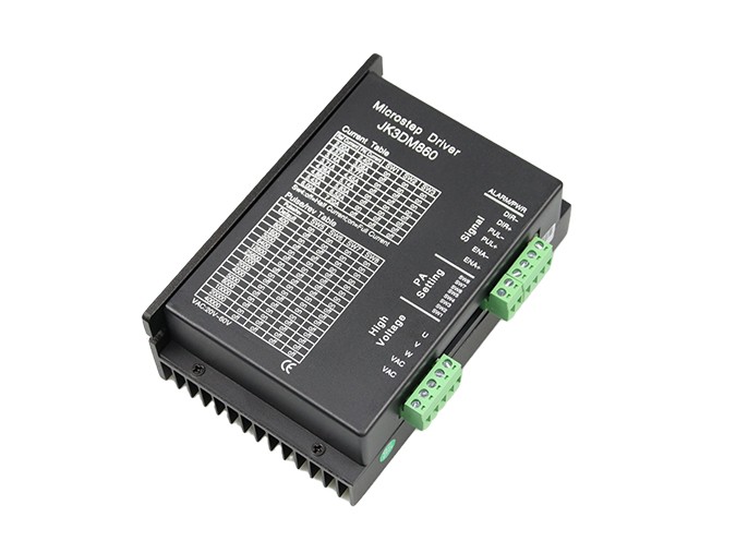
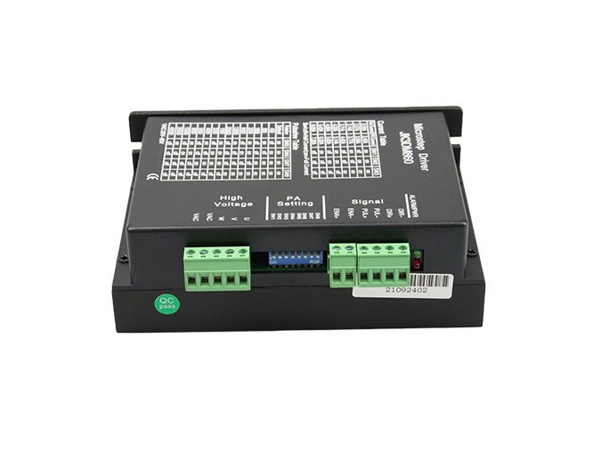
Signal interfaces | PUL+ and PUL- are the positive and negative side of control pulse signal; DIR+ and DIR- are the positive and negative side of direction signal; ENA+ and ENA- are the positive and negative side of enable signal. |
Motor interfaces | U, V, W are connected to winding of motor. If you need to backward, any 2 wires can be reversed. |
Power interfaces | It uses DC power supply. Recommended operating voltage is 20VAC~60VAC OR 24VDC~80VDC, and power consumption should be greater than 350W. |
Indicator lights | There are two indicator lights. Power indicator is green. When the driver power on, the green light will always be lit. Fault indicator is red, when there is over-voltage or over-current fault, the red light will always be lit; after the driver fault is cleared, if re-power the red light will be off. |
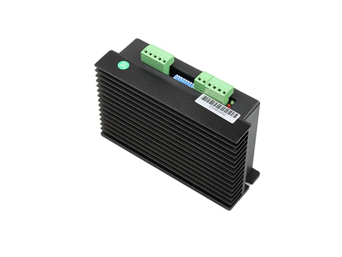
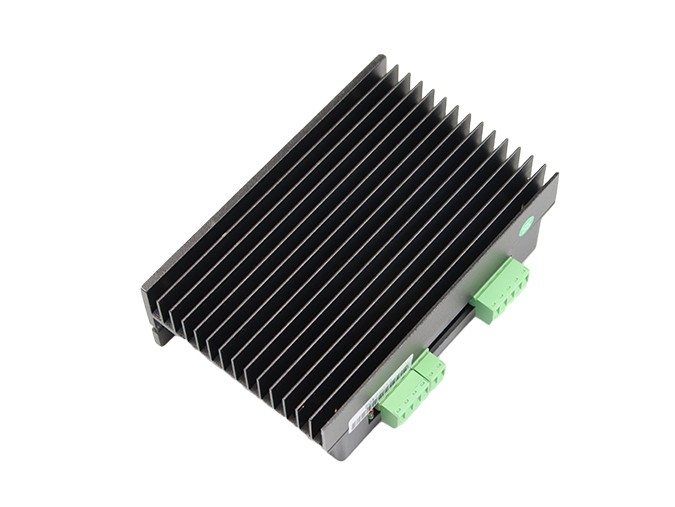
Installation instructions | Driver dimensions:150×98×51mm, please refer to dimensions diagram. Please leave 10CM space for heat dissipation. During installation, it should be close to the metal cabinet for heat dissipation. |
Applications:
Suitable for a variety of large-scale automation equipments and instruments. For example: labeling machine, cutting machine, packaging machine, plotter, engraving machine, CNC machine tools and so on. It always performs well when applied for equipment which requires for low-vibration, low-noise, high-precision and high-velocity.
Product Dimension:

Nema 34 3 Phase Stepper Motor.
FAQS:
1. How can get it started as soon as possible when you first use the drive?
After you correctly connect the power cord, the motor line, the Hall line, the external potentiometer slowly accelerates. After the motor is turned correctly, you can test the enable, direction and other functions. If you are unfamiliar with the product, the initial use should be done after the test. And then it can be installed to the actual use.
2. What will come about if power supply is reverse?
It will immediately burn the drive.
3. What is the maximum of the upper control signal voltage ?
The maximum voltage of the speed regulation signal is 5V. Exceeding this voltage will cause the drive to burn.
4. After the driver has been working for a long time, the shell is hot. Is it normal?
Yes, it is. At room temperature, after long working hours, it is up to 90 degrees. And it will not affect the performance.
5. The power indicator is light, but the motor does not turn and shift, what is the reason?
There may be a mistake in the phase line and the Hall line. Please re-energize the wiring according to the motor manual.
6. Can my motor speed transferred to 6000 with this drive?
The maximum speed of the brushless motor is determined by the parameters of the motor itself. The drive can control the motor speed from 0 to the highest speed.
7. I already have a motor and how to install this drive after wiring?
You must first determine the motor phase and the definition of the Hall line, and then you can connect it with wires. If you are not sure, you need to ask the motor manufacturers. Incorrect wiring can cause damage to the drive.
8. Can I add some features on this drive or do new product development?
Yes, please contact us.