- To Share:

- |


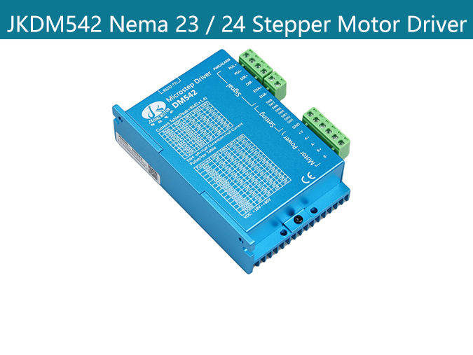
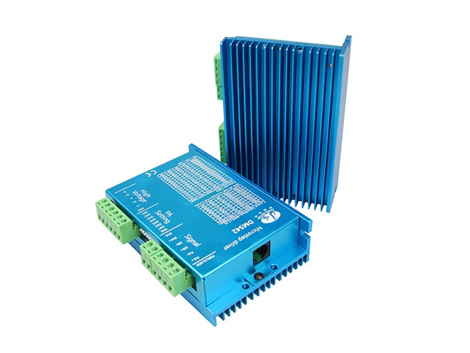
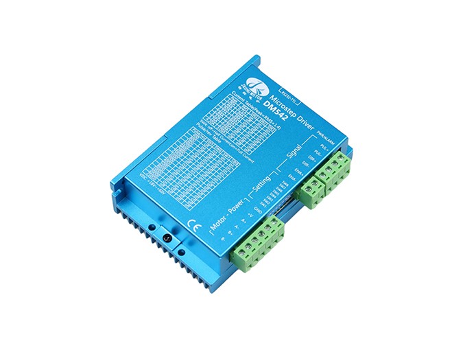
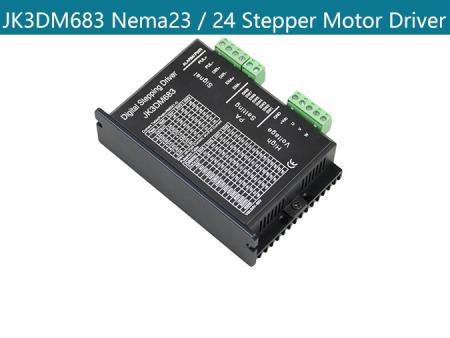
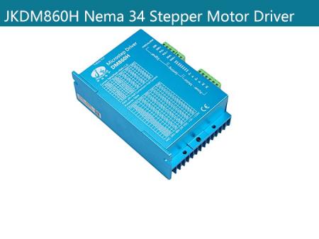
JKDM542 Stepper Motor Driver
Product Description:
Main features:
Product Type: Nema 23 Stepper Motor / Nema 24 Stepper Motor Driver
Feature summary:High start speed; High hording torque under high speed; High performance, low price
Place of Origin:china
Minimum order quantity:10pcs
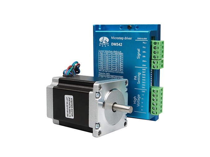
Support Motor: Nema 23 Stepper Motor and Nema 24 Stepper Motor
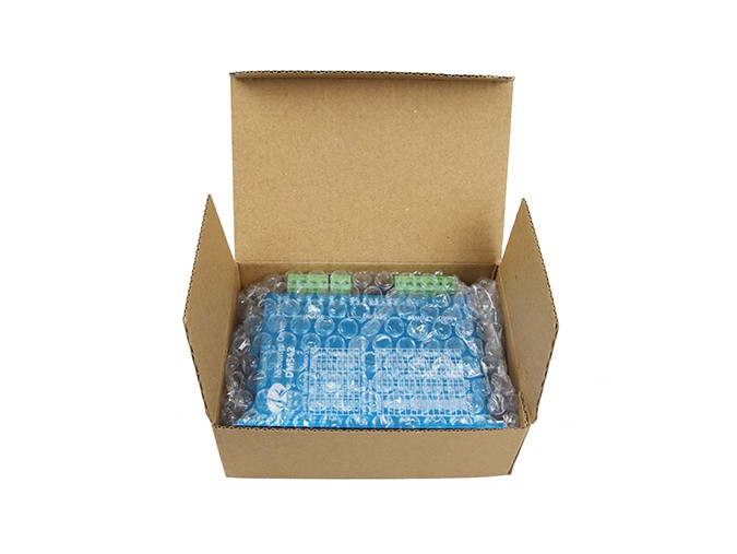
Packing:The sample is packed in carton,the batch with plastic pallet
Delivery time:Standard product: 7-10days
Customized product: 25-30days
Transaction mode:EXW, FOB, FCA, CIF, FAS, CFR, CPT, CIP, DAF, DEQ, DDU, DDP...
Mechanical Size:

Product Overview:
1、Average current control, 2-phase sinusoidal output current drive
2、8 channels output phase current setting
3、Offline command input terminal
4、High start speed
5、High hording torque under high speed
6、High performance, low price
7、Opto-isolated signal I/O
8、Overvoltage, under voltage, overcorrect, phase short circuit protection
9、15 channels subdivision and automatic idle-current reduction
10、Motor torque is related with speed, but not related with step/revolution
The connection between the driver and the two-phase hybrid stepping motor is four-wire. The motor windings are connected in parallel and in series, and the connection method is good. The high-speed performance is good, but the driver current is large (1.73 times the motor winding current). The drive current is equal to the motor winding current.
Product Parameters:
Features | |
Input voltage | 18~60V DC |
Output current | 1.0A~4.2A(Peak) |
Input current | <4A |
Humidity | Not condensation, no water droplets |
Consumption | Consumption:80W |
Using environment | -10 ~ 45 ℃, avoid dust and corrosive gas |
Storage environment | -40~+70℃ |
Weight | 200g |
Control Signal | |
Symbol | Name |
PUL+ | Pulse signal + |
PUL- | Pulse signal - |
DIR+ | Direction signal+ |
DIR- | Direction signal- |
ENA+ | Enable signal + |
ENA- | Enable signal - |
Noted: When the offline enable signal is active, the drive fault is reset, any valid pulses are disabled, the output power component of the drive is turned off, and the motor has no holding torque.
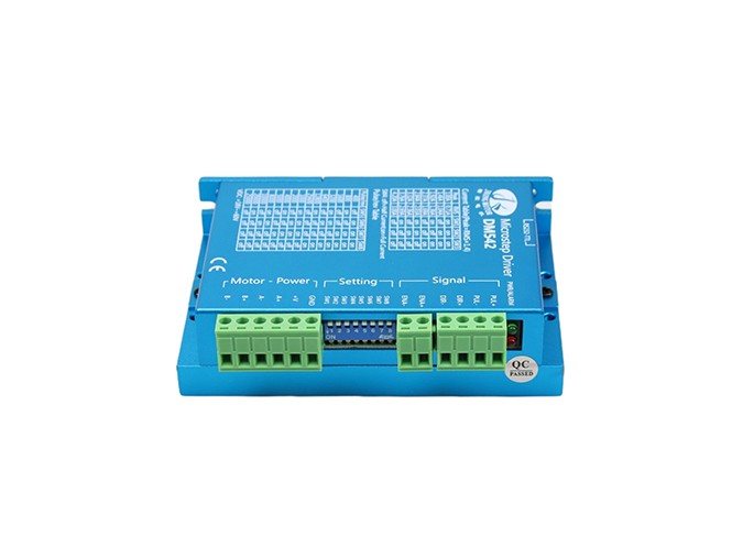
Motor and power | ||
Symbol | Name | Remark |
A+ | Phase A+ | / |
A- | Phase A- | / |
B+ | Phase B+ | / |
B- | Phase B- | / |
+V | Input Power + | +18~60V |
GND | Input Power - | 0V |
DIP switch setting | ||||
In order to drive stepping motors with different torques, the user can set | ||||
the output phase current (effective value) of the driver by the DIP switches | ||||
SW1, SW2 and SW3 on the driver panel. The output current corresponding | ||||
to each switch position, different models of drivers The corresponding output | ||||
current values are different. See the table below for details. | ||||
SW1 | SW2 | SW3 | PEAK (A) | RMS (A) |
ON | ON | ON | 1.00 | 0.71 |
OFF | ON | ON | 1.46 | 1.04 |
ON | OFF | ON | 1.92 | 1.36 |
OFF | OFF | ON | 2.37 | 1.69 |
ON | ON | OFF | 2.84 | 2.03 |
OFF | ON | OFF | 3.32 | 2.36 |
ON | OFF | OFF | 3.76 | 2.69 |
OFF | OFF | OFF | 4.20 | 3.00 |
SW4:‘OFF’ has no semi-flow function; ‘ON’ has semi-flow function.
The semi-flow function means that after 500ms without stepping pulse, the output current of the driver is automatically reduced to 70% of the rated output current to prevent the motor from heating.
MicroSteps Setting | ||||||||
Pulse | 400 | 800 | 1600 | 3200 | 6400 | 12800 | 25600 | / |
SW5 | OFF | ON | OFF | ON | OFF | ON | OFF | / |
SW6 | ON | OFF | OFF | ON | ON | OFF | OFF | / |
SW7 | ON | ON | ON | OFF | OFF | OFF | OFF | / |
SW8 | ON | ON | ON | ON | ON | ON | ON | / |
Pulse | 1000 | 2000 | 4000 | 5000 | 8000 | 10000 | 20000 | 25000 |
SW5 | ON | OFF | ON | OFF | ON | OFF | ON | OFF |
SW6 | ON | ON | OFF | OFF | ON | ON | OFF | OFF |
SW7 | ON | ON | ON | ON | OFF | OFF | OFF | OFF |
SW8 | OFF | OFF | OFF | OFF | OFF | OFF | OFF | OFF |
Control Signal Connection:

Note:
1、When the VCC value is 5V, R is shorted;
2、When the VCC value is 12V, R is 1K, which is greater than 1/8W resistance;
3、When the VCC value is 24V, R is 2K, which is greater than 1/8W resistance;
4、R must be connected to the signal terminal of the controller.
Adjustment of troubleshooting | ||
Alarm indicator | Reasons | Measures |
LED off turn | Wrong connection for power | Check wiring of power |
Low-voltages for power | Enlarge voltage of power | |
Motor doesn’t run, without | Wrong connection of stepper motor | Correct its wiring |
holding torque | RESET signal is effective when offline | Make RESET ineffective |
Motor doesn’t run, but maintains | Without input pulse signal | Adjust PMW & signal level |
holding torque | ||
Motor runs wrong direction | Wrong wires’ connection | Change connection for any of 2 wires |
Wrong input direction signal | Change direction setting | |
Motor’s holding torque is | Too small relative to current setting | Correct rated current setting |
Acceleration is too fast | Reduce the acceleration | |
Motor torque is too small | Motor stalls | Rule out mechanical failure |
Driver does not match with the motor | Change a suitable driver | |
Nema 23 Stepper Motor / Nema 24 Stepper Motor.
FAQS:
1. How can get it started as soon as possible when you first use the drive?
After you correctly connect the power cord, the motor line, the Hall line, the external potentiometer slowly accelerates. After the motor is turned correctly, you can test the enable, direction and other functions. If you are unfamiliar with the product, the initial use should be done after the test. And then it can be installed to the actual use.
2. What will come about if power supply is reverse?
It will immediately burn the drive.
3. What is the maximum of the upper control signal voltage ?
The maximum voltage of the speed regulation signal is 5V. Exceeding this voltage will cause the drive to burn.
4. After the driver has been working for a long time, the shell is hot. Is it normal?
Yes, it is. At room temperature, after long working hours, it is up to 90 degrees. And it will not affect the performance.
5. The power indicator is light, but the motor does not turn and shift, what is the reason?
There may be a mistake in the phase line and the Hall line. Please re-energize the wiring according to the motor manual.
6. Can my motor speed transferred to 6000 with this drive?
The maximum speed of the brushless motor is determined by the parameters of the motor itself. The drive can control the motor speed from 0 to the highest speed.
7. I already have a motor and how to install this drive after wiring?
You must first determine the motor phase and the definition of the Hall line, and then you can connect it with wires. If you are not sure, you need to ask the motor manufacturers. Incorrect wiring can cause damage to the drive.
8. Can I add some features on this drive or do new product development?
Yes, please contact us.