- To Share:

- |


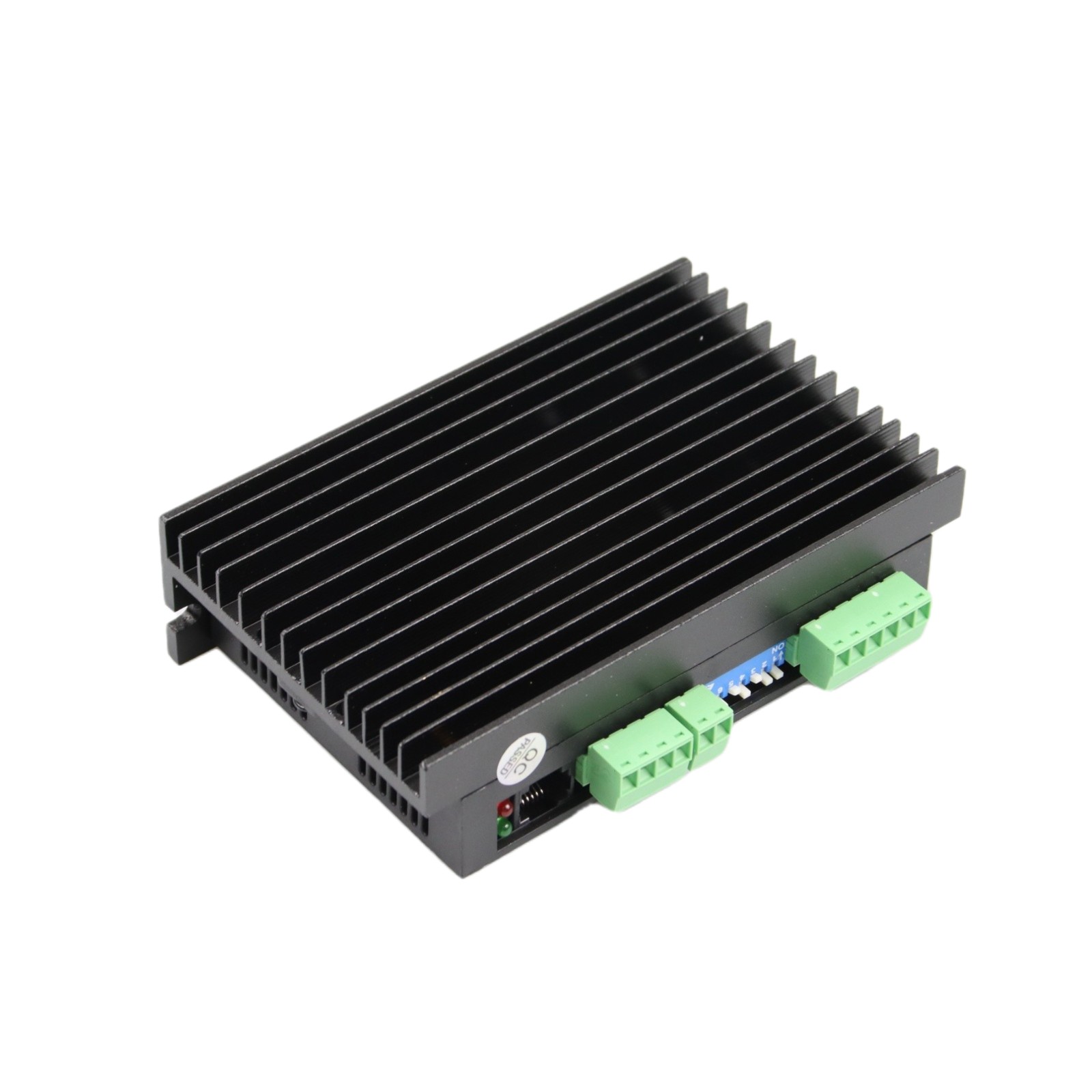
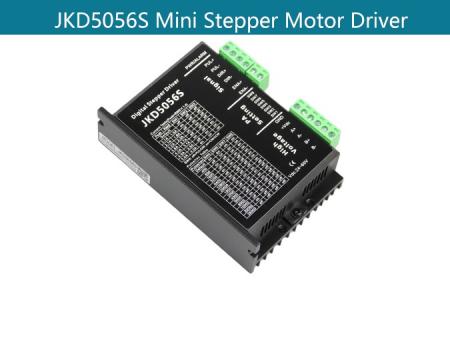
JKD5056S Nema 34 2-phase Stepper Motor Driver
Product Description:
Main features:
Product Type: Nema 34 Stepper Motor Driver
Feature summary:High start speed; High hording torque under high speed; High performance, low price
Place of Origin:china
Minimum order quantity:10pcs
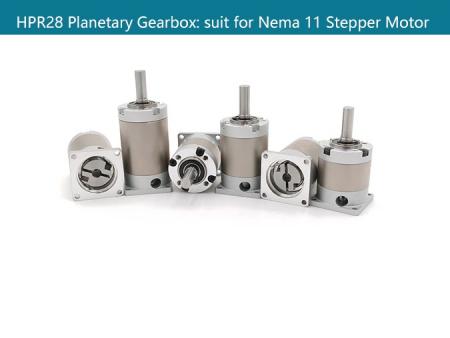
Support Motor: Nema 34 Stepper Motor
Packing:The sample is packed in carton,the batch with plastic pallet
Delivery time:Standard product: 7-10days
Customized product: 25-30days
Transaction mode:EXW, FOB, FCA, CIF, FAS, CFR, CPT, CIP, DAF, DEQ, DDU, DDP...
Product Overview:
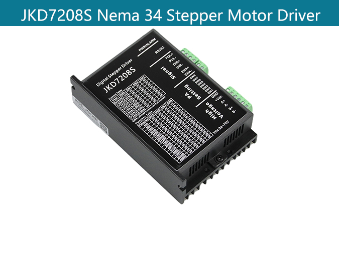
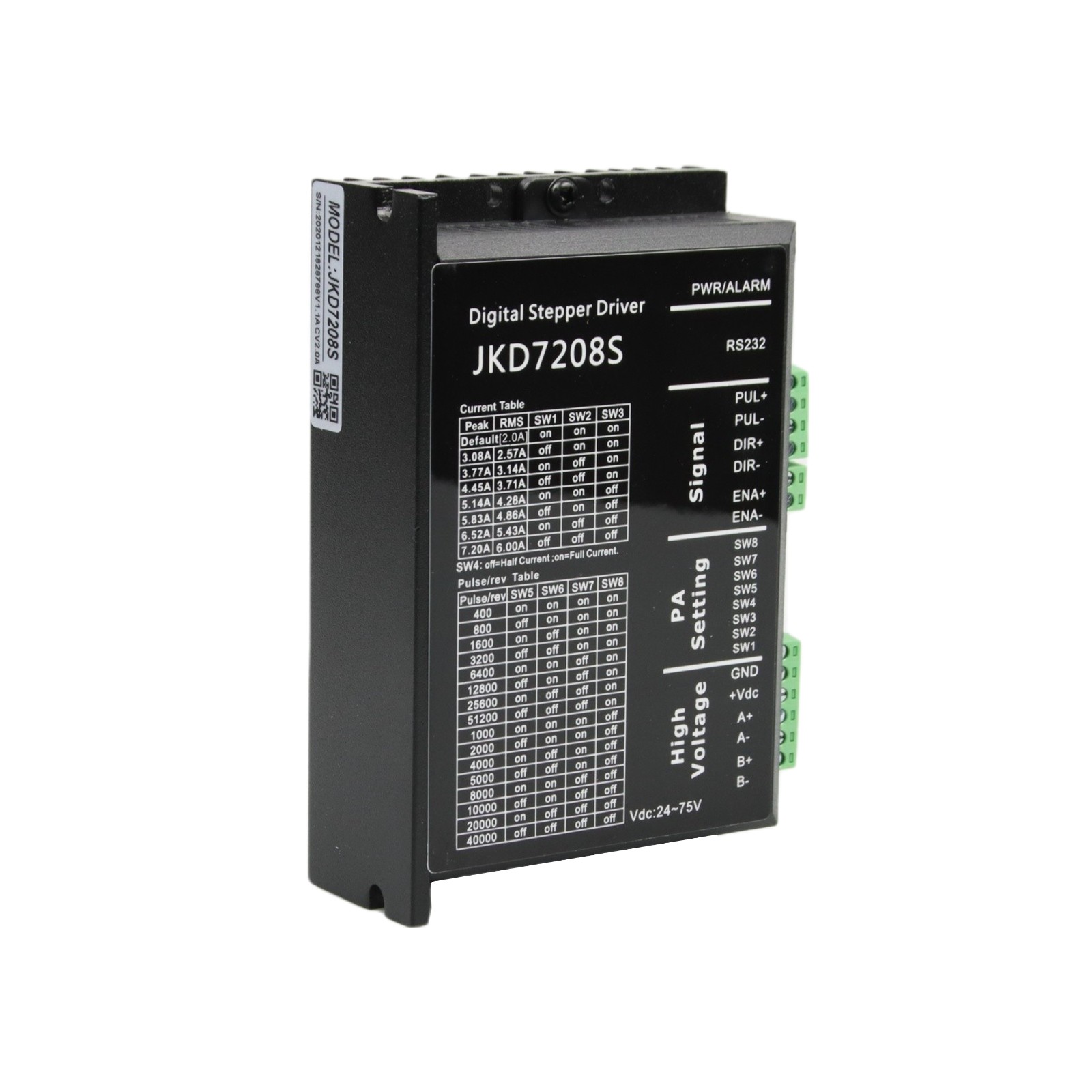
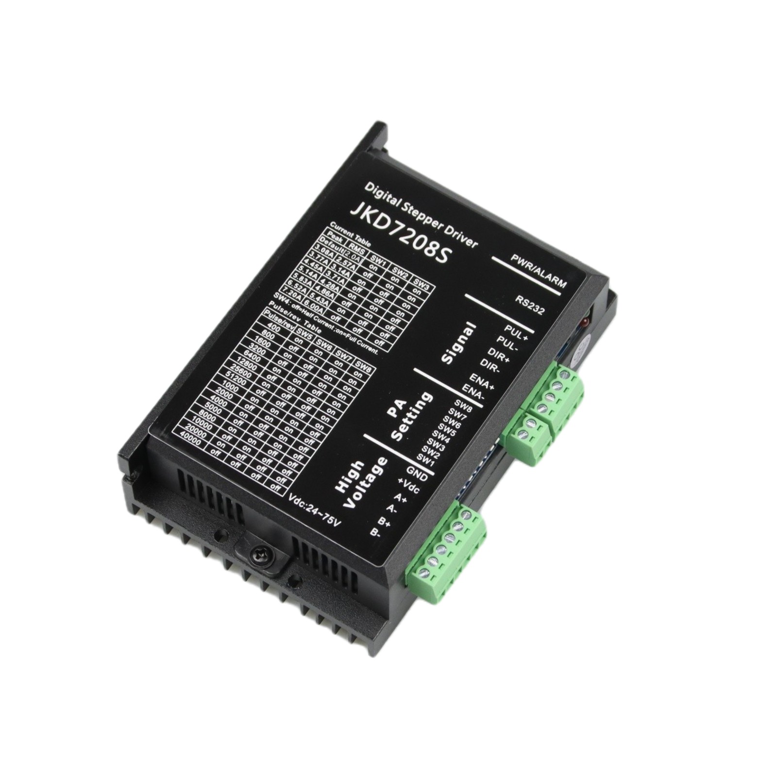
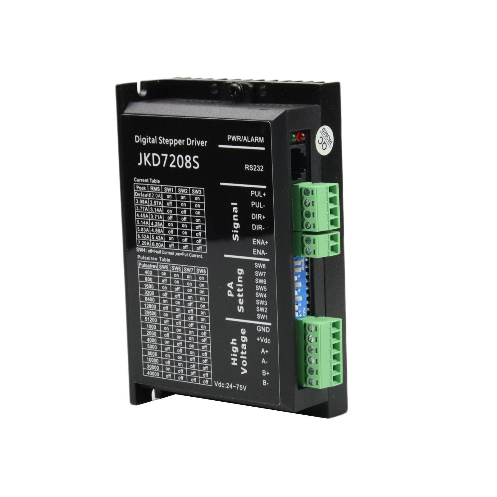
JKD7208S is a new digital stepper motor driver by JKONGMOTOR. It adopts the latest 32-bit DSP digital processing technology. The drive control algorithm adopts advanced variable current technology and advanced frequency conversion technology. The driver has small heating, small motor vibration and stable operation. Users can set any subdivision within 200 ~ 51200 and any current value in the rated current to meet the application needs in most occasions. Thanks to the built-in micro-subdivision technology, the subdivision effect can be achieved even under the condition of low subdivision. The operation is smooth and the noise is ultra-small under low, medium and high speed. The driver integrates the parameter auto-adjust function, which can automatically generate optimal operating parameters for different motors to maximize the performance of the motor.
Features:
●New 32-bit DSP technology
●Ultra-low vibration noise
●Built-in high subdivision
●Automatic parameter adjustment function when power on
●Variable current control reduces the heating of the motor
●The current automatically halve at rest
●Can drive two phase stepping motors of 4, 6, 8 lines
●Optical isolation differential signal input
●The pulse response frequency can reach to 500KHz(Factory default 200KHz)
●The current setting is convenient and can choose between 0.1 to 7.2A
●Subdivision setting range is between 200 to 51200
●Has the protection function of overpressure, underpressure and overcurrent
Application:
Suitable for all kinds of small and medium sized automation equipment and instruments, such as: engraving machine, marking machine, cutting machine, laser lighting, plotter, cnc machine, automatic assembly equipment, etc. It use very well in the equipment that user expects small noise, and high peed.
Electrical indicators:
Instruction | JKD7208S | |||
Minimum | Typical | Maximum | Unit | |
The output current | 0.1 | - | 7.2 | A |
Input voltage | 24 | 48 | 75 | VDC |
Control signal input current | 6 | 10 | 16 | mA |
Control signal interface level | 4.5 | 5 | 28 | Vdc |
Input signal minimum pulse width | 1.5 | - | - | us |
Stepper pulse frequency | 0 | - | 200 | KHz |
Insulation resistance | 100 | MΩ | ||
Using environment and parameters:
Cooling method | Natural cooling or forced air cooling | |
Using environment | occasion | Can not be placed next to other heating equipment, should avoid dust, oil mist, corrosive gas, too big humidity and strong vibration place, prohibit to have combustible gas and conductive dust |
temperature | -5℃ ~ +50℃ | |
humidity | 40 ~ 90%RH | |
vibration | 5.9m/s2MAX | |
Storage temperature | -20℃~80℃ | |
Using altitude | Below 1000 metres | |
Weight | About 280 g | |
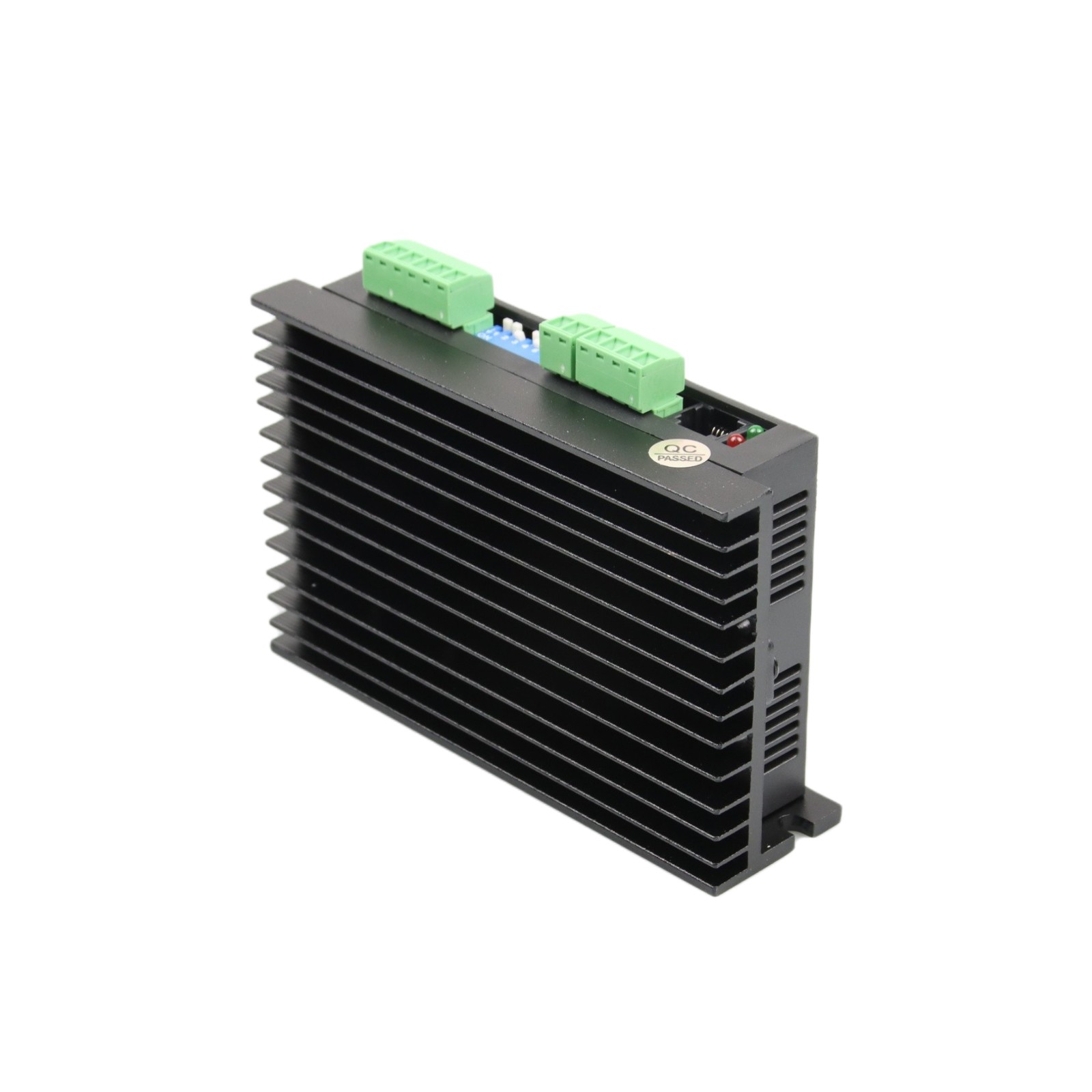
Enhanced heat dissipation:
1)Driver’s reliable working temperature control in 66 ℃, the motor’s working temperature control in 85 ℃
2)We suggest automatic half stream mode,when the motor is stopped and the current is reduced by half to reduce the heating of the motor and actuator
3)When installing the driver, use vertical side installation to make the cooling tooth form a stronger air convection. The fan shall be installed near the actuator in the time necessary to heat the heat and ensure that the driver works in the range of reliable working temperature.
Control signal interface circuit:
Name | Function |
PUL+ | Pulse signal: pulse rising edge is effective; In PUL high level,voltage is 4.5 ~ 28Vdc, and the low level, voltage is 0 ~ 0.5v. In order to reliably respond to the pulse signal, the pulse width should be greater than 1.5μs |
PUL- | |
DIR+ | Direction signal: high/low level signal, to ensure reliable commutation of motor, directional signal should be established before the pulse signal at least 2μs. The initial direction of the motor is connect to motor wiring, change winding (e.g., A +, A - exchange) can change the direction of the motor running, In DIR high level,the voltage is 4.5 ~ 28 VDC,in low level,voltage is 0 ~ 0.5 V. |
DIR- | |
ENA+ | Enable signal: this input signal is used to enable or prohibit. ENA+ connect 4.5 ~ 28Vdc, ENA- connect low level (or internal optical coupling), the actuator will cut off the electrical current to keep the motor in a free state and the stepper pulse is not responsive. When this function is not required, the enable signal can be suspended. |
ENA- |
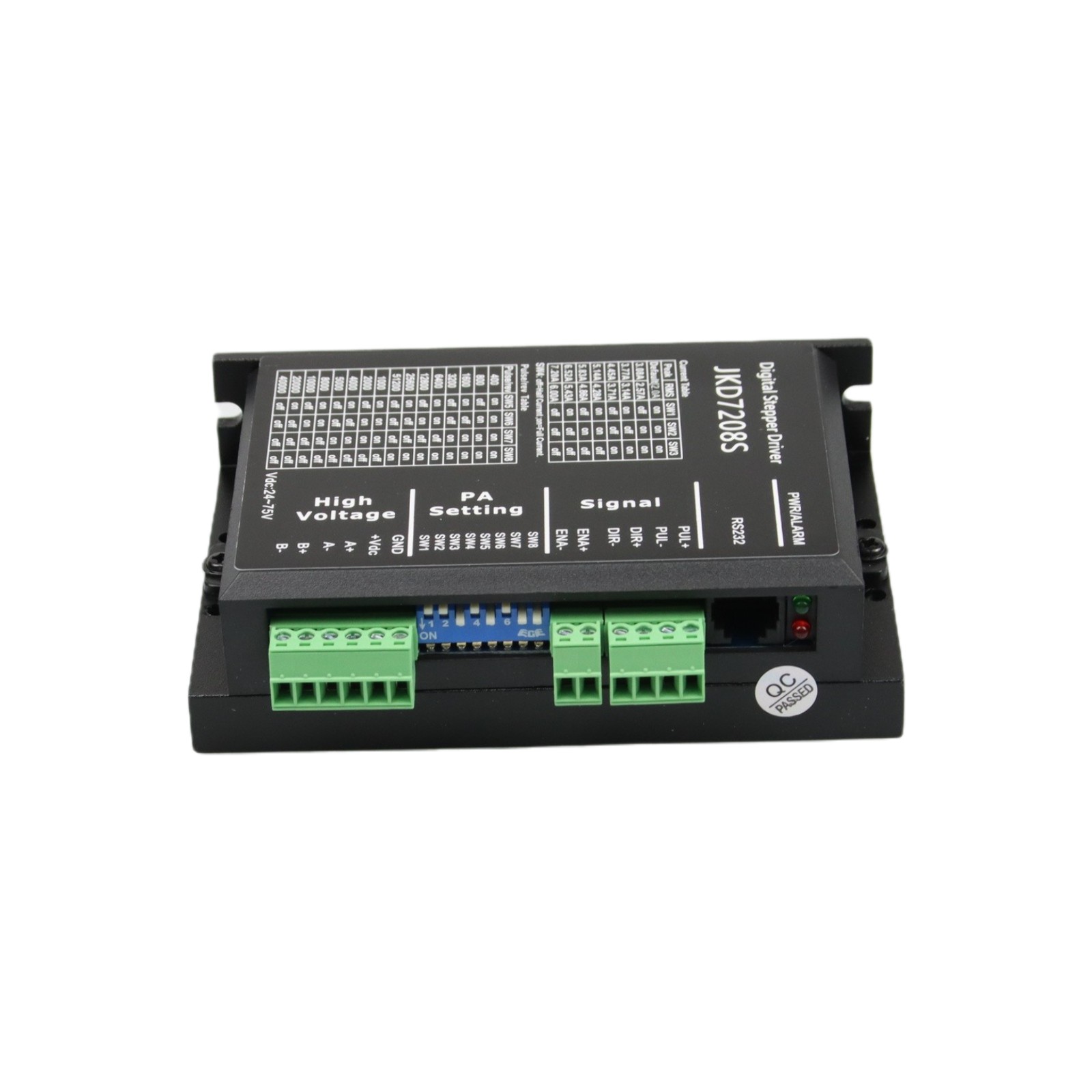
High voltage interface:
Name | Function |
GND | DC power grounding |
+Vdc | DC power positive, dc 24~75 VDC, recommended for 48Vdc. |
A+、A- | Motor A phase coil interface |
B+、B- | Motor B phase coil interface |
232 Communication interface:
It is possible to connect a PC or STU debugger with a dedicated serial cable, and forbid charged plug. Through STU or the PC software ProTuner, the subdivision and current value, effective edge and single double pulse all can be set, and can also be used for the elimination and adjustment of the resonance point.
Terminals No. | Signal | Name | Instruction |
1 | NC | ||
2 | +5V | 5V positive of power supply | Only by external STU |
3 | TxD | RS232 sender | |
4 | GND | 5V power grounding | 0V |
5 | RxD | RS232 receiver | |
6 | NC |
Note: JKD7208S and PC, text display or STU servo debugger connection cable must be special cable,please confirmwith us before use.
Current setting:
1)Working (dynamic) current setting
Output peak current | Output average current | SW1 | SW2 | SW3 | Current self-setting |
Default[2.0A] | on | on | on | When SW1, SW2, SW3 are set to off off off, the required current can be set by PC software,max 7.2 A, resolution 0.1 A. Default current is 2 A without setting | |
3.08A | 2.57A | off | on | on | |
3.77A | 3.14A | on | off | on | |
4.45A | 3.71A | off | off | on | |
5.14A | 4.28A | on | on | off | |
5.83A | 4.86A | off | on | off | |
6.52A | 5.43A | on | off | off | |
7.20A | 6.00A | off | off | off | |
2) Static current setting
Static current can set by SW4 DIP switch settings, off means the static current is set to half of dynamic current, on means static current and dynamic current is the same. SW4 should be set to off for general use, can reduce the heating of the motor and the driver. About 400ms after the pulse train stopped it will automatically reduced to half current (60% of the actual value), the heat will reduced to 30% theoretically .
Step/Rev. | SW5 | SW6 | SW7 | SW8 | Subdivide description |
400 | on | on | on | on | Subdivision Description: The driver subdivision adopts the internal default subdivision. Users set the subdivision number through the PC software ProTuner or STU debugger, the minimum value is 1, the resolution Is 1, the maximum is 51200. |
800 | off | on | on | on | |
1600 | on | off | on | on | |
3200 | off | off | on | on | |
6400 | on | on | off | on | |
12800 | off | on | off | on | |
25600 | on | off | off | on | |
51200 | off | off | off | on | |
1000 | on | on | on | off | |
2000 | off | on | on | off | |
4000 | on | off | on | off | |
5000 | off | off | on | off | |
8000 | on | on | off | off | |
10000 | off | on | off | off | |
20000 | on | off | off | off | |
40000 | off | off | off | off |
Parameter self-tuning function:
If switch the SW4 back and forth within 1 second, the driver can auto-complete the motor parameters and internal parameters adjustment; when the conditions like motor, supply voltage changes, please conduct a self-tuning, otherwise, the motor may not run normal. Note that the pulse can not be input at this time and the direction signal should not change.
Method 1:SW4 from on to off, and then off back to on in 1 second;
Method 2: SW4 from off to on, and then by the dial back to off within 1 second.
Note: This model has power-on auto tuning function.
Power supply options:
JKD7208S can working normally in the specified range of voltage, and use non-regulated DC power supply is best, also can use transformer reduction + bridge rectifier + capacitor filter. However,should notice that voltage ripple peak value after rectifier should not exceed its maximum specified voltage. It is recommended that users use DC voltage lower than the maximum voltage to supply power and avoid the fluctuation of power grid beyond the working range of driver voltage.
If using a regulated switching power supply, be aware that the output current range of the switching power supply needs to be maximized.
Please note:
1) When wiring, pay attention to the positive and negative poles of the power supply.
2) Best use non-regulated power supply;
3) When using non-regulated power supply, the power supply current output capacity should be greater than 60% of the driver set current;
4) When use regulated switching power supply, the output current of the power supply should be greater than or equal to the working current of the driver;
5) To reduce costs, two or three drives can share a power supply, but should ensure that the power supply is large enough.
Motor matching:
JKD7208S can be used to drive 4,6,8-wire two-phase, four-phase hybrid stepper motor, step angle of 1.8 degrees and 0.9 degrees are both applicable. When selecting a motor, it is mainly determined by the torque of the motor and the rated current. The size of the torque is mainly determined by the motor size. The motor torque is large for large size; and the current is mainly related to the inductance, small inductance motor has high speed performance, but the is current larger.
Common problems:
Phenomenon | Possible problems | Solutions |
Motor not running | Power light is off | Check the power supply circuit, normal power supply |
Motor shaft has torque | The pulse signal is weak and increase the current to 7-16mA | |
Too small subdivision | Choose right subdivision | |
If the current setting too small | Choose right current | |
Driver is protected | Re-power | |
The enable signal is low | This signal is pulled high or not connect | |
No responsive to control signal | No powered | |
Motor direction error | Wrong wiring of motor | Exchange any two lines of the same phase of the motor (eg A +, A-exchange connection positions) |
Motor circut is open | Check and connection right | |
Alarm indicator light | Wrong wiring of motor | Check the wiring |
Voltage is too high or too low | Check the power supply | |
Motor or driverdamaged | Change the motor or driver | |
Wrong position | The signal is disturbed | Eliminate interference |
No connect grounding | Grounding right | |
Motor circut is open | Check and connection right | |
Wrong subdivision | Set right subdivision | |
Small current | Increase the current | |
The motor can’t run when acceleration | Acceleration time is too short | Acceleration more time |
Too samll motor torque | Select a large torque motor | |
Low voltage or current is too small | Increase the voltage or current |

FAQS:
1. How can get it started as soon as possible when you first use the drive?
After you correctly connect the power cord, the motor line, the Hall line, the external potentiometer slowly accelerates. After the motor is turned correctly, you can test the enable, direction and other functions. If you are unfamiliar with the product, the initial use should be done after the test. And then it can be installed to the actual use.
2. What will come about if power supply is reverse?
It will immediately burn the drive.
3. What is the maximum of the upper control signal voltage ?
The maximum voltage of the speed regulation signal is 5V. Exceeding this voltage will cause the drive to burn.
4. After the driver has been working for a long time, the shell is hot. Is it normal?
Yes, it is. At room temperature, after long working hours, it is up to 90 degrees. And it will not affect the performance.
5. The power indicator is light, but the motor does not turn and shift, what is the reason?
There may be a mistake in the phase line and the Hall line. Please re-energize the wiring according to the motor manual.
6. Can my motor speed transferred to 6000 with this drive?
The maximum speed of the brushless motor is determined by the parameters of the motor itself. The drive can control the motor speed from 0 to the highest speed.
7. I already have a motor and how to install this drive after wiring?
You must first determine the motor phase and the definition of the Hall line, and then you can connect it with wires. If you are not sure, you need to ask the motor manufacturers. Incorrect wiring can cause damage to the drive.
8. Can I add some features on this drive or do new product development?
Yes, please contact us.