- To Share:

- |


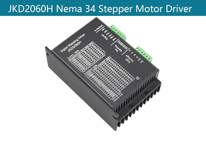
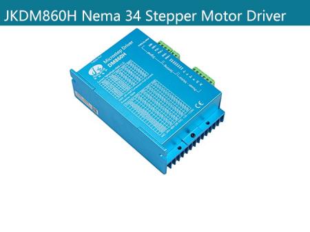
JKD2060H Stepper Motor Driver
Product Description:
Main features:
Product Type: Nema 34 Stepper Motor Driver
Feature summary:High-performance, low price, micro-step, Automatic idle-current reduction, Optical isolating signals I/O, Max response frequency up to 200Kpps, Low temperature rise, smooth motion, Online adaptive PID technology.
Place of Origin:china
Minimum order quantity:10pcs
Support Motor: Nema 34 Stepper Motor
Packing:The sample is packed in carton,the batch with plastic pallet
Delivery time:Standard product: 7-10days
Customized product: 25-30days
Transaction mode:EXW, FOB, FCA, CIF, FAS, CFR, CPT, CIP, DAF, DEQ, DDU, DDP...
Product Overview:
The JKD2060H is a new generation digital 2-phase stepper motor driver, based on a 32-bit DSP processor, combination of the anti-resonance, low noise, micro-step and low temperature rise technology significantly improve the performance of the stepper motor, has low noise, small vibration, low temperature rise and high-speed torque. The driver use online adaptive PID technology, without manual adjustment can be automatically generated optimal parameters for different motors, and achieve the best performance.
Supply voltage range from 18VAC to 80VAC or from 24VDC to 110VDC, suitable for driving various 2-phase hybrid stepping motors which phase current below 7.2A. The microstep can be set from full step to 51200steps/rev and the output current can be set form 2.4A to 7.2A; with automatic idle-current reduction, self-test, overvoltage, under-voltage and over-current protection.
Product Parameters:
Parameter | Min | Typical | Max | Unit |
Input Voltage(DC) | 24 | - | 110 | VDC |
Input Voltage(AC) | 18 | - | 80 | VAC |
Output current | 0 | - | 7.2 | A |
Pulse Signal Frequency | 0 | - | 200 | KHZ |
Logic Signal Current | 7 | 10 | 16 | MA |
Features:
1、 High-performance, low price
2、 micro-step
3、 Automatic idle-current reduction
4、Optical isolating signals I/O
5、 Max response frequency up to 200Kpps
6、 Low temperature rise, smooth motion
7、Online adaptive PID technology
Applications:
Suitable for a variety of large-scale automation equipments and instruments. For example: labeling machine, cutting machine, packaging machine, plotter, engraving machine, CNC machine tools and so on. It always performs well when applied for equipment which requires for low-vibration, low-noise, high-precision and high-velocity.
1、Current setting:
RMS | Peak | SW1 | SW2 | SW3 |
2.00A | 2.40A | on | on | on |
2.57A | 3.08A | off | on | on |
3.14A | 3.77A | on | off | on |
3.71A | 4.45A | off | off | on |
4.28A | 5.14A | on | on | off |
4.86A | 5.83A | off | on | off |
5.43A | 6.52A | on | off | off |
6.00A | 7.20A | off | off | off |
Standstill Current Setting:
SW4 is used for standstill current setting. OFF meaning that the standstill current is half of the dynamic current; and ON meaning that standstill current is the same as the selected dynamic current. Usually the SW4 is set to OFF, in order to reduce the heat of the motor and driver.
2、Microstep Setting:
Step/Rev | SW5 | SW6 | SW7 | SW8 |
Default | on | on | on | on |
800 | off | on | on | on |
1600 | on | off | on | on |
3200 | off | off | on | on |
6400 | on | on | off | on |
12800 | off | on | off | on |
25600 | on | off | off | on |
51200 | off | off | off | on |
1000 | on | on | on | off |
2000 | off | on | on | off |
4000 | on | off | on | off |
5000 | off | off | on | off |
8000 | on | on | off | off |
10000 | off | on | off | off |
20000 | on | off | off | off |
40000 | off | off | off | off |
Control Signal connector | |
Name | Description |
DIR- | Direction signal negative |
DIR+ | Direction signal positive |
PUL- | Pulse signal negative |
PUL+ | Pulse signal positive |
ENA- | Enable signal negative, usually left unconnected(enable) |
ENA+ | Enable signal positive, usually left unconnected(enable) |
4、Power and Motor Connector:
AC | Power supply +24~+90 VDC or 20V-60VAC |
AC | |
A+ | Motor phase A |
A- | |
B+ | Motor phase B |
B- |
5、 Problems and Solutions:
problems | Possible cause | solutions |
Motor is not rotating | No power supply | Check the power supply |
No control signal | Check the control signal | |
The driver is disabled | Don’t connected the enable signal or enable the driver | |
ALM lights | Supply voltage is too high or too low | Check the supply voltage |
Motor line short-circuit | Check motor lines eliminate the short-circuit | |
Motor line wrong connect | Check the motor wiring | |
Motor or drive failure | Replace the motor or drive | |
Motor rotates in the wrong direction | Motor phases connected in reverse | Reverse the phases line |
Motor line break | Change the phases are connected | |
Inaccurate Position | The Micro steps set incorrectly. | Set the correct segments |
The motor load is too heavy. | Increasing the current | |
Control signal is interfered | Eliminate interference | |
Motor Stalled | Power supply voltage too low | Increasing the supply voltage |
Accelerating time is too short. | Extend the acceleration time | |
Current setting is too small | Increasing the current | |
Motor torque is too small | Replace the motor |
FAQS:
1. How can get it started as soon as possible when you first use the drive?
After you correctly connect the power cord, the motor line, the Hall line, the external potentiometer slowly accelerates. After the motor is turned correctly, you can test the enable, direction and other functions. If you are unfamiliar with the product, the initial use should be done after the test. And then it can be installed to the actual use.
2. What will come about if power supply is reverse?
It will immediately burn the drive.
3. What is the maximum of the upper control signal voltage ?
The maximum voltage of the speed regulation signal is 5V. Exceeding this voltage will cause the drive to burn.
4. After the driver has been working for a long time, the shell is hot. Is it normal?
Yes, it is. At room temperature, after long working hours, it is up to 90 degrees. And it will not affect the performance.
5. The power indicator is light, but the motor does not turn and shift, what is the reason?
There may be a mistake in the phase line and the Hall line. Please re-energize the wiring according to the motor manual.
6. Can my motor speed transferred to 6000 with this drive?
The maximum speed of the brushless motor is determined by the parameters of the motor itself. The drive can control the motor speed from 0 to the highest speed.
7. I already have a motor and how to install this drive after wiring?
You must first determine the motor phase and the definition of the Hall line, and then you can connect it with wires. If you are not sure, you need to ask the motor manufacturers. Incorrect wiring can cause damage to the drive.
8. Can I add some features on this drive or do new product development?
Yes, please contact us.