- To Share:

- |


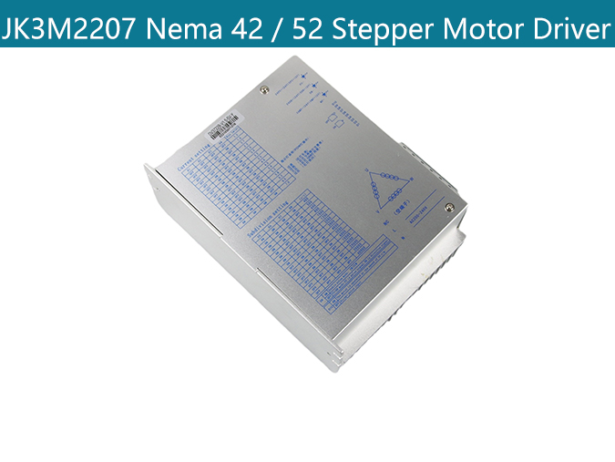
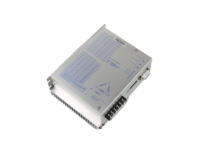
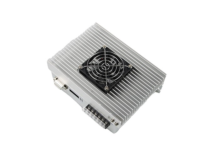
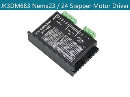
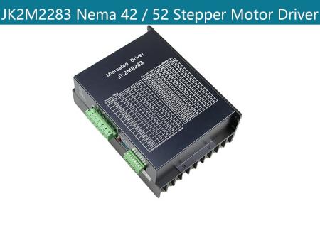
JK3M2207 3 Phase Stepper Motor Driver
Product Description:
Main features:
Product Type: Nema 42 3 Phase Stepper Motor or Nema 52 3 Phase Stepper Motor Driver
Feature summary:High-performance, low price, micro-step, Automatic idle-current reduction, Optical isolating signals I/O, Max response frequency up to 200Kpps, Low temperature rise, smooth motion, Online adaptive PID technology.
Place of Origin:china
Minimum order quantity:10pcs
Support Motor: Nema 42 3 Phase Stepper Motor or Nema 52 3 Phase Stepper Motor
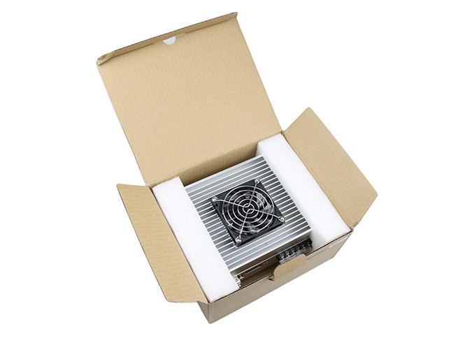
Packing:The sample is packed in carton,the batch with plastic pallet
Delivery time:Standard product: 7-10days
Customized product: 25-30days
Transaction mode:EXW, FOB, FCA, CIF, FAS, CFR, CPT, CIP, DAF, DEQ, DDU, DDP...
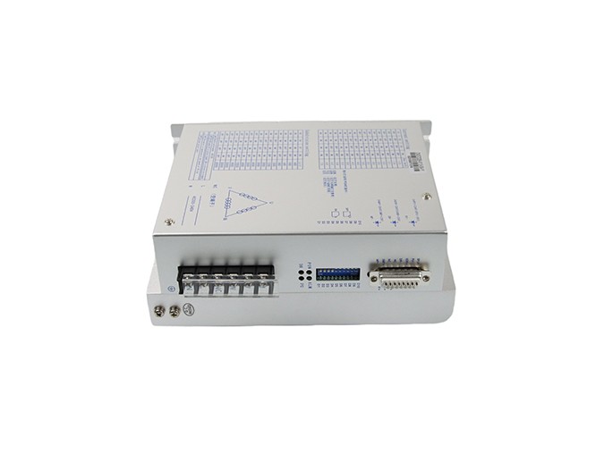
Product Overview:
The JK3MD2207 is full digital 3 phase stepper driver based on DSP control. As a new generation of digital stepper motor drives, it is combined the advanced DSP control chip with the three-phase inverter driver module.The drive voltage of which is from 160V to 230VAC.It is designed for using with the 3 phase hybrid stepper motor of all kinds with 0.57mm to 130mm outside diameter, regulated phase current from 1.3A to 7.0A. The circuit that it adopts is similar to the circuit of servo control which enables the motor to run smoothly without noise and vibration. Moreover, its torque is far greater than 2 and 5 phase hybrid stepping motors.Furthemore, the highest micro step is 60000ppr. Due to these obvious advangtages, it is widely used in middle and big size numerical control devices such as curving machine, CNC machine, computer embroider machine, packing machine and etc.
Features:
1. 16 channels constant angle, constant torque micro steps, highest micro step: 60000ppr
2. Highest response frequency: 200Kpps
3. Current of winding will be reduced by approximately 50% when no step pulse command is received for 1.5 second
4. Opto-isolated signal I/O
5. Drive current is adjustable in 16 channels from 1.3A/phase to 7.0A/phase
6. Single power supply from 110V to 230VAC
7. Phase terminal memory function (motor phase terminal is memorized after input pulse train stopping 3s and it is recovered when stepper driver power on or signal MF changes from low level to high level)
Applications:
Suitable for a variety of large-scale automation equipments and instruments. For example: labeling machine, cutting machine, packaging machine, plotter, engraving machine, CNC machine tools and so on. It always performs well when applied for equipment which requires for low-vibration, low-noise, high-precision and high-velocity.
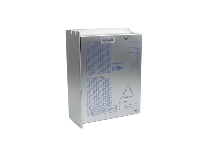
1. CURRENT SETTING: Stepper driver working current is set by DIP switches D1 to D4
Working current(A) | JK3MD2207 | 1.3 | 1.6 | 2.1 | 2.3 | 2.5 | 3.0 | 3.2 | 3.5 |
D1 | OFF | OFF | OFF | OFF | OFF | OFF | OFF | OFF | |
D2 | OFF | OFF | OFF | OFF | ON | ON | ON | ON | |
D3 | OFF | OFF | ON | ON | OFF | OFF | ON | ON | |
D4 | OFF | ON | OFF | ON | OFF | ON | OFF | ON | |
Working current | JK3MD2207 | 4.0 | 4.5 | 5.0 | 5.3 | 5.8 | 6.2 | 6.5 | 7.0 |
D1 | ON | ON | ON | ON | ON | ON | ON | ON | |
D2 | OFF | OFF | OFF | OFF | ON | ON | ON | ON | |
D3 | OFF | OFF | ON | ON | OFF | OFF | ON | ON | |
D4 | OFF | ON | OFF | ON | OFF | ON | OFF | ON | |
2. SUBDIVISION (MICRO STEP) SETTING:
The subdivision (micro step) is set by DIP switches D5 to D8, 16 channels in total. D9 and D10 are used to set the driver function.
Subdivision (micro step) ppr | 400 | 500 | 600 | 800 | 1000 | 1200 | 2000 | 3000 |
D5 | ON | ON | ON | ON | ON | ON | ON | ON |
D6 | ON | ON | ON | ON | OFF | OFF | OFF | OFF |
D7 | ON | ON | OFF | OFF | ON | ON | OFF | OFF |
D8 | ON | OFF | ON | OFF | ON | OFF | ON | OFF |
Subdivision (micro step) ppr | 4000 | 5000 | 6000 | 10000 | 8000 | 20000 | 30000 | 60000 |
D5 | OFF | OFF | OFF | OFF | OFF | OFF | OFF | OFF |
D6 | ON | ON | ON | ON | OFF | OFF | OFF | OFF |
D7 | ON | ON | OFF | OFF | ON | ON | OFF | OFF |
D8 | ON | OFF | ON | OFF | ON | OFF | ON | OFF |
D9 | ON, double pulse: PU is positive pulse signal, DR is negative pulse signal | |||||||
OFF, single pulse: PU is pulse signal, DR is direction signal | ||||||||
D10 | Self detect switch (OFF: accept external pulse, ON: the driver send pulse to make the motor work at the speed of 30r/m) | |||||||
3. I/O SIGNAL:
All of the input signals are opto-isolated. To ensure the built-in high speed optocoupler effective, the drive capacity of current for control signal must be 15mA or more. Because of internal optocoupler current-limiting resistor, if input signal voltage of stepper driver is above 5V, please use external resistor R to limit current.
When input signal voltage is:
+5V: R1=0, R2=0;
+12V: R1=510Ω, R2=820Ω;
+24V: R1=1.2KΩ, R2=1.8KΩ
4. CAUTION:
1. Supply voltage shouldn’t exceed 220VAC.
2. Input control signal is 5V, current-limiting resistance should be connected when it is over 5V.
3. Input pulse signal is effective with the falling edge.
4. Alarm indicator lights and the driver stops working when the driver temperature is over 80℃. It restarts working until the temperature falls to 50℃. The heat sink is needed when overheat occurs.
5. Alarm indicator lights when overcurrent (short of load) occurs. Please check motor’s connection and other shorts and turn the power supply on after removing the trouble.
6. Alarm indicator lights when no motor connected or poor connection. Please check motor’s connection and turn the power supply on after removing the trouble.
5. Problems and Solutions:
Phenomenon | Cause | Action |
Motor is not working | Indicators don’t light up | Check if the electricity supply is normal |
ALM indicator light up | Check stepper driver if overcurrent, overheat occurs, or no motor connected | |
The motor shaft is locked, motor dose not work | Check the external control signal | |
Indicator display normal, the motor shaft is not locked | Check if signal MF is effective | |
The motor is squealing | Max. speed set is too high | Reduce the max. speed |
Acceleration time short | Increase acceleration time or increase stepper driver pulse filter constant | |
Motor locates inaccurately | Micro step is incorrect | Select the correct micro step |
Stepper motor overloads | Change the other motor or increase the running current of stepper driver | |
Leakage current | stepper driver or motor are not grounded well | Make sure the driver and motor are grounded |
Driver , motor heats up | Stepper driver’s running current is large or the working environment temperature is high | Decrease the running current of stepper driver or improve the ventilation and heat elimination for working environment |
Product Dimension:

Nema 42 3 Phase Stepper Motor or Nema 52 3 Phase Stepper Motor.
FAQS:
1. How can get it started as soon as possible when you first use the drive?
After you correctly connect the power cord, the motor line, the Hall line, the external potentiometer slowly accelerates. After the motor is turned correctly, you can test the enable, direction and other functions. If you are unfamiliar with the product, the initial use should be done after the test. And then it can be installed to the actual use.
2. What will come about if power supply is reverse?
It will immediately burn the drive.
3. What is the maximum of the upper control signal voltage ?
The maximum voltage of the speed regulation signal is 5V. Exceeding this voltage will cause the drive to burn.
4. After the driver has been working for a long time, the shell is hot. Is it normal?
Yes, it is. At room temperature, after long working hours, it is up to 90 degrees. And it will not affect the performance.
5. The power indicator is light, but the motor does not turn and shift, what is the reason?
There may be a mistake in the phase line and the Hall line. Please re-energize the wiring according to the motor manual.
6. Can my motor speed transferred to 6000 with this drive?
The maximum speed of the brushless motor is determined by the parameters of the motor itself. The drive can control the motor speed from 0 to the highest speed.
7. I already have a motor and how to install this drive after wiring?
You must first determine the motor phase and the definition of the Hall line, and then you can connect it with wires. If you are not sure, you need to ask the motor manufacturers. Incorrect wiring can cause damage to the drive.
8. Can I add some features on this drive or do new product development?
Yes, please contact us.