- To Share:

- |


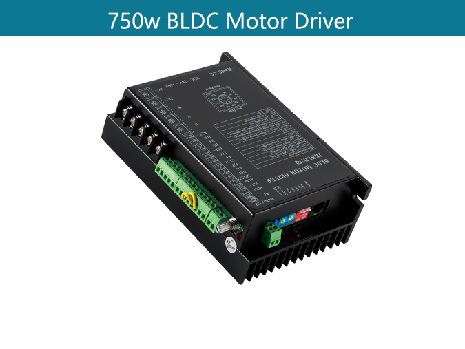
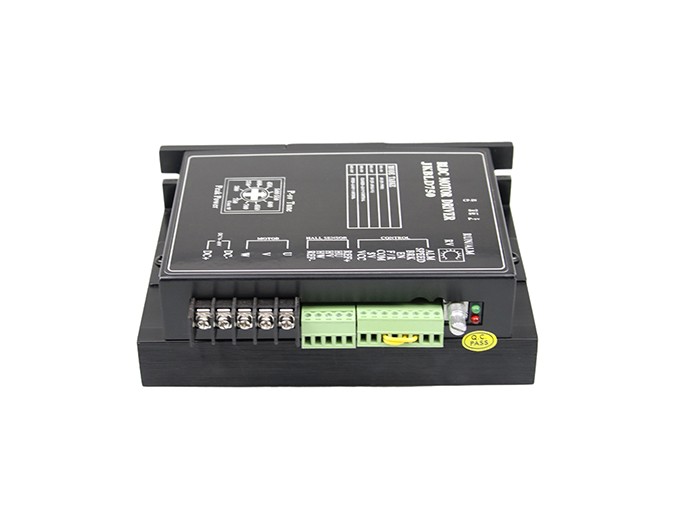
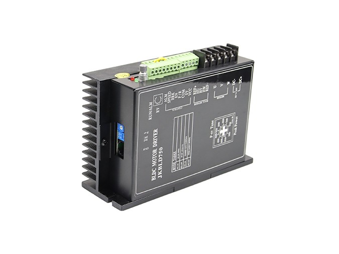
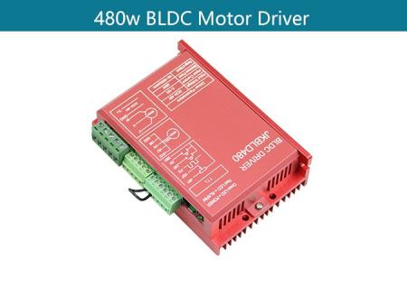
JKBLD750 Brushless DC Motor Driver
Brushless DC motors generally have three coils, with semiconductor switches connected to each of these. Turning the semiconductor switches on and off in the correct sequence alternates the current flow, which generates the rotating magnetic field that causes the motor to turn.
There are three leads for the BLDC motor and five Hall leads. The eight leads must be corresponding to the lead of the controller. Otherwise, the electric motor cannot move normally.
Depending on the positioning method, BLDC motor controllers can be: sensor (they use Hall-effect sensors, encoders, and other position sensors); sensorless (they measure back electromotive force).
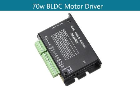
JKBLD-750 is designed by Jkongmotor and mainly for BLDC motors of 48v less 750w. With DSP or PWM controlling technology, it has features of high torque, low vibration, low noise, closed loop control and rich speed control modes
Product Description:
Main features:
Product Type: 750W BLDC Motor Driver
Place of Origin:china
Minimum order quantity:10pcs
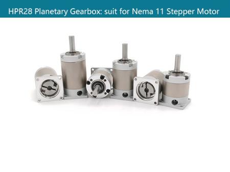
Support Motor: Brushless dc motor less of 750w
Packing:The sample is packed in carton,the batch with plastic pallet
Delivery time:Standard product: 7-10days
Customized product: 25-30days
Transaction mode:EXW, FOB, FCA, CIF, FAS, CFR, CPT, CIP, DAF, DEQ, DDU, DDP...
Mechanical Size:

Functional Overview:
The JKBLD750 BLDC motor drive is a high performance, cost-effective 3phase BLDC motor drive, which can provide power output Max 750VA.The design is based on advanced DSP technology and feature high torque, low noise, low vibration, PID speed loop, PID current loop, over current protection, over load protection and a combined use of manual speed adjustment and automatic speed adjustment.
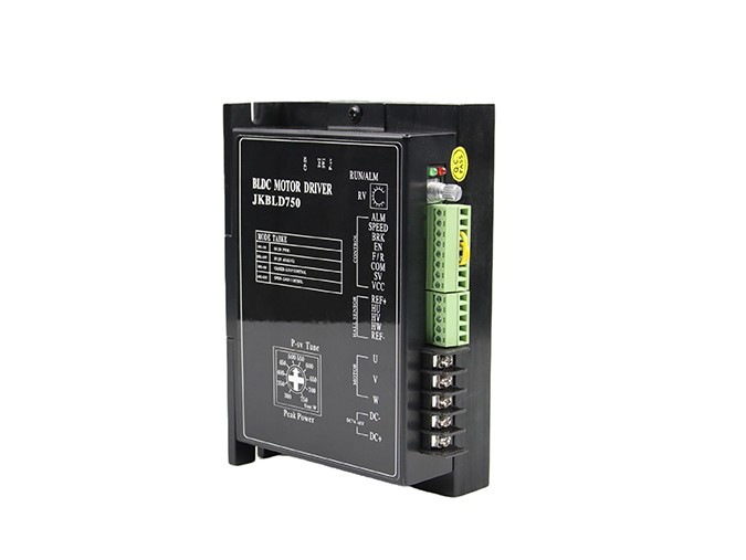
Connection Definition:
Mark | Definition |
DC+/DC- | DC Power Input (DC24V~DC48V) |
U,V,W | Motor Lead Wire |
Hu,Hv,Hw | Hall Sensor Lead Wire |
REF+ | Hall Sensor Power Supply + |
REF- | Hall Sensor Power Supply - |
VCC | External Potentiometer Power Supply ( Internal Power Supply Only) |
SV | External Potentiometer ( No Connection When Adjusting Speed With Internal Potentiometer ) or Pulse Rate In Note① |
COM | Common (Low Level/Ground) |
F/R | Direction: Low Level/CCW High Level or No Connection/CW Note ② |
EN | Enable: High Level/Stop Low Level/Run Note ② |
BRK | Quick Brake: High Level/Stop Low Level/Run Note ② |
SPEED | Speed Signal Output |
ALARM | Alarm Signal Output |
Note①: Potentiometer/10KΩ or analog signal DC 0V~+5V (Change
internal switch J1/DC0-10V).Turn off the internal potentiometer RV
when using an external potentiometer to adjust the motor speed.
Note②:High level/5V (5mA)
Electrical Specifications
Parameter | Min | Rated | Max | Unit |
Motor Hall Sensor Angle | 120°/240° | / | ||
DC Power Input | 18 | 48 | 50 | V |
Drive Current Output | 0 | 25 | 45 | A |
Suitable Motor Speed | 0 | / | 20000 | rpm |
Hall Sensor Voltage | 4.5 | 5 | 5.5 | V |
Hall Sensor Current | / | 20 | / | mA |
External Potentiometer | / | 10K | / | Ω |
Speed Adjustment Instruction:
◆ Motor Speed Adjusted By The Internal Potentiometer RV:
SW1/ Off (Factory setting)
◆ Motor Speed Adjusted By Analog DC 0V~+5V Input:
SW1/ Off (Factory setting) set J1 (internal) as ![]() (user Setting) RV—Turn Off
(user Setting) RV—Turn Off
◆ Motor Speed Adjusted By Analog DC 0V~+10V Input:
SW1/ Off (Factory setting) set J1 (internal) as ![]() (user Setting) RV—Turn Off
(user Setting) RV—Turn Off
◆ Motor Speed Adjusted By Pulse Rate Input:
Pulse rate: 0K—3KHZ Speed linear modulation
Pulse amplitude: 5V Pulse duty ratio: 50%
SW1/ On (User setting) RV—Turn Off
J7 (Internal)/ Switch on with the jumper cap on J1 (User setting)
◆ Motor Speed Quick Response Setting:
SW2/ On ( User setting): PID closed loop--quick speed response
SW2/Off (Factory setting): Open loop--Normal speed response
◆ Motor Speed Signal Output:
Connecting SPEED and COM to get pulse output F=N*P/60
F—Pulse output frequency
P—Pole number of BLDC motor
◆ Drive Alarm Output:
When drive alarm, it will break over with the port of COM and be low
level. The drive stop to work and alarm light run.
◆ Lead Wire Connection: Take care of the sequence of U,V,W
Motor Parameter set by Jkongmotor BLDD-01 (Optional) :
◆ RS232 Communication Interface CP-in
The BLDD48-45A BLDC motor drive support RS232 communication Protocol to set motor run-up time, etc. When choose ICAN BLDD-01 as host controller, the operating process and instruction as below:
◆ Jkongmotor BLDD-01 Motor Setting Panel Operating Process:
Connect to CP-in (BLDD48-45A)
SW1/ Off (Factory setting) RV—Turn Off
BLDD-01 Parameter Setting Table:
Function code | Mode | Setting range | Unit | Factory setting | Alteration |
P000 | Control mode | 00 BLDD-01 control 01 None host control | None Panel control | ★ | |
P001 | Panel setting speed | 0~Rated speed | RPM | ★ | |
P002 | Run-up time | 0.1~9.9 | S | 0.2 | ★ |
P003 | Motor pole number setting | 1~99 | Pole pairs | 4 | ★ |
P004 | CW CCW | 01 CW 00 CCW | 01 | ★ | |
P005 | Reserved | ||||
P006 | Reserved |
◆ BLDD-01 Panel Setting Process:
1. Turn on the power supply, press <Set> to stop the motor
2. Press <▲> or <▼> to choose the mode you need (Press Esc return and motor running)
3. Press <Set> enter into parameter mode (Press Esc return and motor running)
4. Press <![]() > or <
> or <![]() > to change the parameter (flashing)
> to change the parameter (flashing)
5. Press <Set> to reserve, parameter stop to flash. Press <Esc> return and motor running.
◆ Panel Protection Mode:
When the system running, panel nixie light shows Err×
Err0 represents Over-voltage or Over-temperature protection
Err1 represents Over-current protection
Err2 represents Hall sensor error protection
◆ Motor Parameter set by other host controller:
BLDD48-45A Communication Protocol (RS232)
1. Communication Interface:
Asynchronous serial communication
Baud rate:2400
Start bit:1 bit
Stop bit:1 bit
Data bit:8 bits
Even/odd parity:none
Communication interface voltage:3.3V
2.Communication Protocol:
Function1:Motor speed controlled by drive BLD-750 itself
Communication format :“i”
Instruction:send a character
Function2:Motor speed controlled by host computer
Communication format:“o”
Instruction:send a character
Function3:Motor speed set by host computer
Communication format:“v”0X00,0X00
Instruction:send a character “v” then two hexadecimal numbers
the high 16bits,the low 16 bits
Function4:run-up time
Communication format:“y“ 0X00
Instruction:send “y“ then a hexadecimal number
Safety attention:
1、The motor and drive wiring must be connected in the power-off state. Do not connect electrical wiring under power.
2、According to the illustrated method, connect the power cord, motor winding wire and Hall signal line correctly. Please pay attention to the order of UVW three-phase must be consistent.
3、Do not disassemble the drive at random to prevent damage.
4、Do not touch all terminals on power-on state.
5、Do not drive without shell operation
6、Impact of the drive may cause damage.
80mm Brushless DC Motor, 86mm Brushless DC Motor, 110mm Brushless DC Motor.
FAQS:
1. How can get it started as soon as possible when you first use the drive?
After you correctly connect the power cord, the motor line, the Hall line, the external potentiometer slowly accelerates. After the motor is turned correctly, you can test the enable, direction and other functions. If you are unfamiliar with the product, the initial use should be done after the test. And then it can be installed to the actual use.
2. What will come about if power supply is reverse?
It will immediately burn the drive.
3. What is the maximum of the upper control signal voltage ?
The maximum voltage of the speed regulation signal is 5V. Exceeding this voltage will cause the drive to burn.
4. After the driver has been working for a long time, the shell is hot. Is it normal?
Yes, it is. At room temperature, after long working hours, it is up to 90 degrees. And it will not affect the performance.
5. The power indicator is light, but the motor does not turn and shift, what is the reason?
There may be a mistake in the phase line and the Hall line. Please re-energize the wiring according to the motor manual.
6. Can my motor speed transferred to 6000 with this drive?
The maximum speed of the brushless motor is determined by the parameters of the motor itself. The drive can control the motor speed from 0 to the highest speed.
7. I already have a motor and how to install this drive after wiring?
You must first determine the motor phase and the definition of the Hall line, and then you can connect it with wires. If you are not sure, you need to ask the motor manufacturers. Incorrect wiring can cause damage to the drive.
8. Can I add some features on this drive or do new product development?
Yes, please contact us.