- To Share:

- |


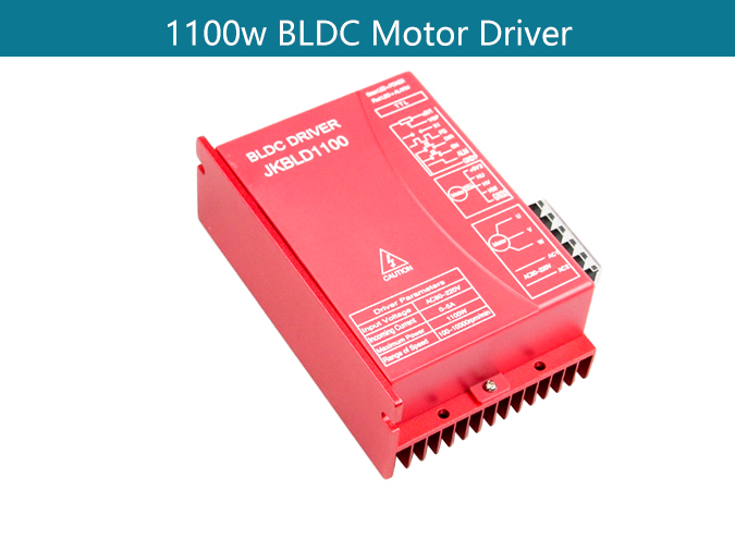
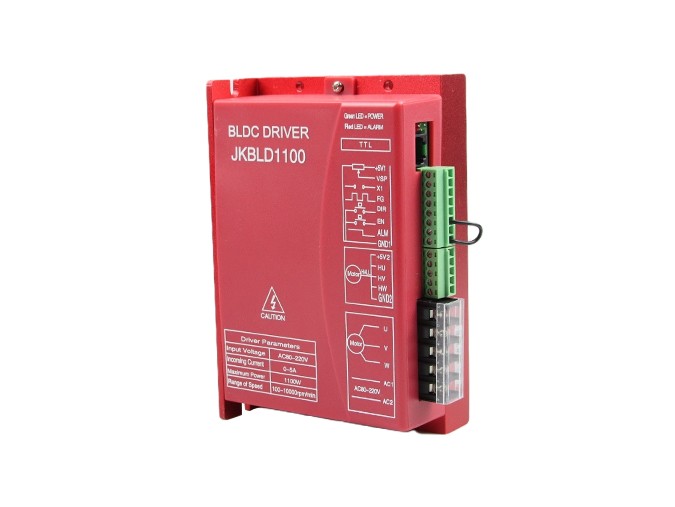
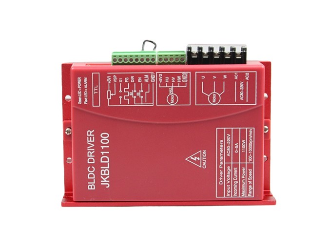
JKBLD1100 Brushless DC Motor Driver
JK1100 is the latest high-tech product of our company, for the field of medium power motor drive. It uses a large-scale integrated circuit to replace the original hardware, so it has higher performance of anti-jamming and fast response ability. It is suitable for all the low voltage three-phase brushless DC motors with peak current below 5A and low voltage AC80V-250V(boards show AC80V-220V) ,whether the motor driver with Hall or not. It is widely used in knitting equipment, medical equipment, food packaging machinery, electric tools and a series of electrical automation control area.
There are several ways to startup a BLDC motor. One way is to use the hall sensor to detect the initial position of the rotor and then startup up the motor by energizing the 3 phases according to an energizing pattern.
In a typical arrangement, the high-side MOSFETs are controlled using pulse-width modulation (PWM) which converts the input DC voltage into a modulated driving voltage. The use of PWM allows the start-up current to be limited and offers precise control over speed and torque.
However, to operate a BLDC motor, you need a specialized motor controller that provides the necessary electrical signals to control the motor's speed, direction, and torque. Let's explore how to select a brushless DC motor controller that will meet the needs of your application.
Product Description:
Main features:
◆It can be connected with an external speed display board BL01, showing the speed, set drive parameters;
◆ It has double speed closed current design with low speed torque and smooth operation;
◆ It has high speed output with the maximum speed of 10000rpm / min;
◆ The speed control mode is an external PWM speed and external potentiometer speed;
◆ It has have EN, DIR,X1 signal control side;
◆ It can output FG signals (optoelectronicisolation, gate output);
◆ It can output ALM signals for the user to detect (optoelectronicisolation, gate output);
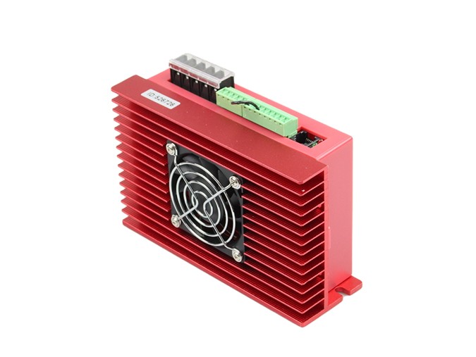
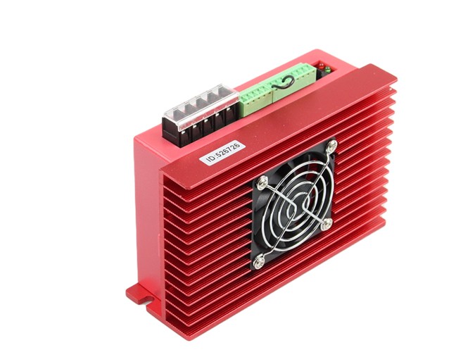
◆ It has over-current, overvoltage, under voltage, fan control and Hall Sensor phase error, motor stalling and other protection functions;
Mechanical Size:

Functional Overview:
1.Run model: square wave, with hall sensor, open loop speed
2.Run model: square wave, with hall sensor, closed loop speed
3.Run model: square wave, without hall sensor, open loop speed
4.Run model: square wave, without hall sensor, closed loop speed
5.Run model: constant-torque device, open loop speed(Don't run for long time with overloading)
6.Run model: constant-torque device, closed loop speed(Don't run for long time with overloading)
On the basis of our upper computer software and hand debugger BL01 , all the above functions can be set by yourself
JK1100 is the latest high-tech product of our company, for the field of medium power motor drive. It uses a large-scale integrated circuit to replace the original hardware, so it has higher performance of anti-jamming and fast response ability. It is suitable for all the low voltage three-phase brushless DC motors with peak current below 5A and low voltage AC80V-250V(boards show AC80V-220V) ,whether the motor driver with Hall or not. It is widely used in knitting equipment, medical equipment, food packaging machinery, electric tools and a series of electrical automation control area.
Electrical Specifications:
(1)Environmental Temperature:25℃
| Power supply | AC80V~220V direct current |
| (Capacity according to motor power selection) | |
| The maximum input current | Not greater than5A (according to motor and rated load) |
| The maximum power | The maximum is 1100W(over power motor is strictly prohibited) |
| Adaptable motor | Adaptable output power ≤750W motor |
| Insulation resistance | General temperature ﹥500MΩ |
| Insulation strength | General temperature and pressure 0.5KV,1minitute |
(2)Environmental Parameter:
Cooling method | Natural air cooling & forced air cooling | |
Environment | Condition | Avoid dust, oil mist and corrosive gases |
Temperature | 0℃~+50℃ | |
Humidity | ﹤80%RH,no condensation, no frost | |
Vibration | ﹤0.5G(4.9m/s2 )10Hz-60Hz (non-continuous operation) | |
Reserved temperature | -20℃~+65℃ | |
Size | 150mmX97.5mmX53mm | |
Weight | About 0.55Kg | |
Note: Due to dramatic changes in the temperature of the storage environment, it is easy to form condensation or frost. In this case, the drive should be placed for 12 hours or more. Until the drive temperature and ambient temperature is consistent, it can be on power.
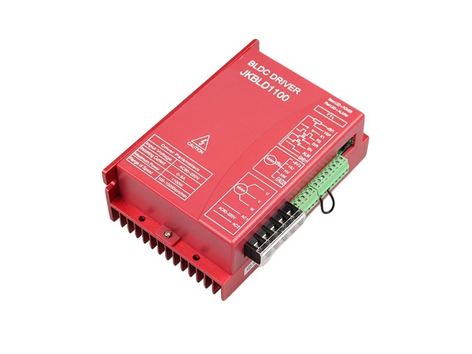
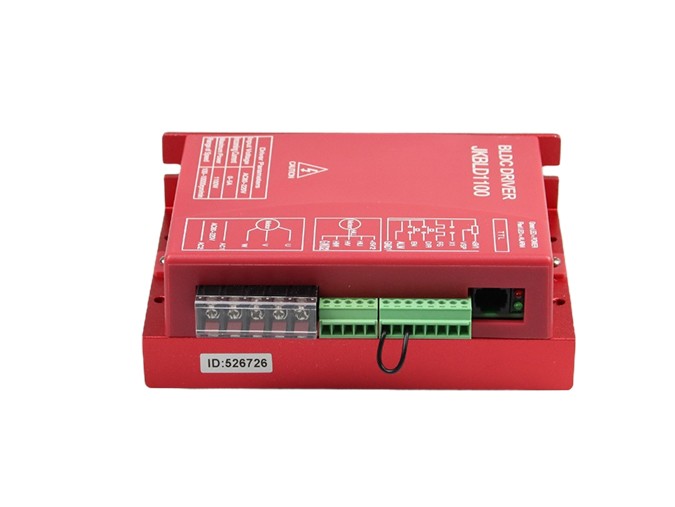
Terminal interface description:
Function | Mark | Description |
Indicator light | POWER | If the green power indicator is lighten, it shows that power is normal. |
ALM | If the red status indicator is slow flash, it means waiting; Quick flash means operation; It always lights meaning faults or off-line; | |
RS232 communication port | TTL | It can be connected with an external speed display board ZM-BL01 to display speed. ZM-BL01 can also set the drive parameters. Details are shown in ZM-BL01 instructions |
Control signal port | +5V1 | Control signal power+( inner power output ) |
VSP | External speed control signal Control way: By connecting with a potentiometer to change VSP, then it can complete 0 ~ 100% speed adjustment. The range is 0-5V | |
X1 | Input signal, brake on low level or to GND1, the red light keep off(Brake braking force can be adjusted by customer’s requirement),When X1 is connected with +5V1 or without any port , motor keeps running. | |
FG | Motor speed pulse output is measuring the frequency of this signal. Then converts it into the actual motor speed. | |
DIR | Rotary direction is controlled by high and low electrical level, motor forward: connected with GND1, motor reversal (anticlockwise) ;without GND1 or connected with +5V, motor forward (clockwise) | |
EN | Connected EN with GND1, motor can work(online status);without connected or high electrical lever, motor can not work(offline status and the red light keep working) | |
ALM | It is signal transfer output. When the power is in danger, the current flow is slow. | |
GND1 | Control signal’s power supply | |
Hall control port | +5V2 | + motor’s Hall power |
HU | Hall sensor signal U phase input | |
HV | Hall sensor signal V phase input | |
HW | Hall sensor signal W phase input | |
GND2 | The motor’s Hall power supply | |
The motor and power | U、V、W | The motor’s three-phase output signal |
GND、V+ | GND、V+ stand for direct current flow. The input power is DC18V~50V.(boards show DC24V-48V) |
Function and method:
Speed mode (VSP/PWM) | 1. The external input speed: two external terminals of the external potentiometer(5K-10K) respectively connected to the driver's GND1 and +5 V1 terminal. If the regulator is connected to the VSP end, you can use an external potentiometer to adjust speed. It can also be made by the other control unit’s (such as PLC, microcontroller, etc.) input analog voltage to VSP side (relative to GND1). VSP port accepts the range of DC 0V ~ +5 V and the corresponding motor speed is 0 ~ rated speed; 2. PWM speed: the PWM’s positive end is connected to the VSP. The negative end connects with GND1. The frequency is 100Hz-100KHz, changing the duty cycle speed. |
Brake (X1) | By control the high and low electrical level between X1 to control the motor status. On low electrical level,X1 stop, when the brake working, the red light off; when X1 is on high electrical level status or without connecting, motor can be allowed to work(Brake braking force can be adjusted by customer’s requirement) |
Speed signal output (FG)
| The drive provides the motor speed pulse signal, which is positive proportion to the motor speed, pulse output way: RPUP 4.7k, open collector output the motor speed (RPM) = F ÷ N× 60 F = actually measured frequency current on the FG foot by frequency table N = Pole logarithm , 2 pole motor, N = 2; 4 pole motor, N = 4 For example: the user selects a 4 pole motor. When the output FG signal is 200Hz, the motor speed = 200 ÷4× 60 = 3000 r / min. |
The motor positive and negative signal(DIR) | By controlling high low-level of DIR to control the motor’s positive and reverse turn. Noticed: Swerved suddenly when motor is at high speed, to avoid the damage of motor and equipment , when DIR get the transform single , we must make motor stop running for 2s, then change the motor direction ,improve speed to the set value. |
Start/Stop signal(EN)
| By controlling high low-level of EN to control the motor’s stop and run. When EN is low level, motor run; when EN is high level or non-connect ,motor stop working, red light keep working. When control motor stop by EN port, it is nature stop, and the run regular is related with overloading inertia. Power Consumption is less than or equal to 30mA. Fault Value: short circuit with EN and GND1 |
Alarm signal (ALM) | Normal output is 5V. When there is over-voltage, over-current, wrong Hall signal or the stop in the motor, the signal is 0V,the red light keep working. |
Safety attention:
1、The motor and drive wiring must be connected in the power-off state. Do not connect electrical wiring under power.
2、According to the illustrated method, connect the power cord, motor winding wire and Hall signal line correctly. Please pay attention to the order of UVW three-phase must be consistent.
3、Do not disassemble the drive at random to prevent damage.
4、Do not touch all terminals on power-on state.
5、Do not drive without shell operation
6、Impact of the drive may cause damage.
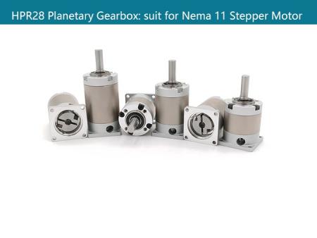
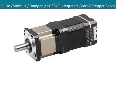
Customized Design:
110mm Brushless DC Motor.
FAQS:
1. How can get it started as soon as possible when you first use the drive?
After you correctly connect the power cord, the motor line, the Hall line, the external potentiometer slowly accelerates. After the motor is turned correctly, you can test the enable, direction and other functions. If you are unfamiliar with the product, the initial use should be done after the test. And then it can be installed to the actual use.
2. What will come about if power supply is reverse?
It will immediately burn the drive.
3. What is the maximum of the upper control signal voltage ?
The maximum voltage of the speed regulation signal is 5V. Exceeding this voltage will cause the drive to burn.
4. After the driver has been working for a long time, the shell is hot. Is it normal?
Yes, it is. At room temperature, after long working hours, it is up to 90 degrees. And it will not affect the performance.
5. The power indicator is light, but the motor does not turn and shift, what is the reason?
There may be a mistake in the phase line and the Hall line. Please re-energize the wiring according to the motor manual.
6. Can my motor speed transferred to 6000 with this drive?
The maximum speed of the brushless motor is determined by the parameters of the motor itself. The drive can control the motor speed from 0 to the highest speed.
7. I already have a motor and how to install this drive after wiring?
You must first determine the motor phase and the definition of the Hall line, and then you can connect it with wires. If you are not sure, you need to ask the motor manufacturers. Incorrect wiring can cause damage to the drive.
8. Can I add some features on this drive or do new product development?
Yes, please contact us.