- To Share:

- |

The reason why the AC servo motors does not move:
In the motion control system, I often encounter that after the wire is connected, the program to drive the motor is written, but the motor just does not move. What is the reason for this, and how to check it?
The possible reasons are:
1、Line missed
2、Related device settings are incorrect
3、Related devices are faulty
The following are related troubleshooting methods, incomplete, but some problems can be checked.
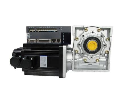
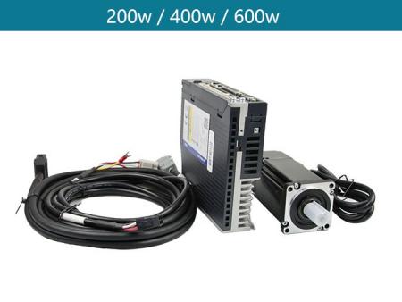
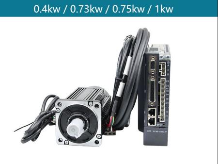
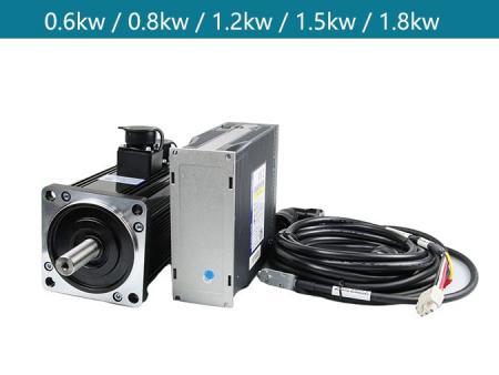
Before troubleshooting, let me talk about the configuration of the motion controller system (the motion control system may be configuration 1, configuration 2, configuration 3, see the picture in this article: pull down to see the picture)
After determining the control system, find a way to conduct a comparison test, such as a system that can be operated and a system that currently has problems. The detailed steps are as follows.
Step 1: Whether the line is normal
Check the wiring, whether there is wrong or missing connection, such as 24V power supply, 5V power supply, common ground, etc., carefully check whether it is consistent with the electrical wiring diagram
Test continuity, there is no problem with cable 1, cable 2, and terminal board.
The resistance of the test circuit, if you need to add a current-limiting resistor but not, please add it, if you do not need to add a current-limiting resistor, but add it, please remove the current-limiting current
If step 1, the test has been completed and there is no problem, go to step 2
Step 2: Check the drive and the motor itself to ensure that there is no problem
Drive motor for trial operation (if possible), then carry out this part of the operation. If the trial operation is successful, proceed to the next operation, otherwise replace the motor or drive and retest.
Make sure there is no problem with the driver setting. Some drivers can be set to internal trigger pulse and external trigger pulse. Please pay more attention
If it is a stepping driver, check whether the subdivision and current settings are correct.
Step 3: Controller settings
1. Enable, if you can hear the drive responding, it means the enable is successful
2. Set the pulse output mode DIR PLUSE or CW CCW and make sure its output mode is consistent with the pulse receiving mode of the driver
Step 4. Start to test its operation process, if it fails to operate, skip to step 6
1. Jog. Determine whether the line of defense is right
2. Point operation.
3. Continue to exercise.
4. Check whether the encoder has a feedback value and whether its feed distance is consistent with the setting, such as setting 1000 pulses to go 1mm. If they are inconsistent, reset them.
Step 5: After the test is completed, start to prepare all programs or system debugging
Step 6: When finished, return to step 4
1. Connect the output of the terminal board with an oscilloscope, make sure it has an output, and judge whether it is consistent with what you want.
2. If they are inconsistent, replace the corresponding device and perform the test operation.


View More(Total0)Comment Lists