- To Share:

- |

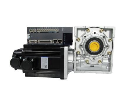
servo motors refers to the engine that controls the operation of mechanical components in the servo system, and is an auxiliary motor indirect speed change device. The servo motor can control the speed and position accuracy very accurately, and can convert the voltage signal into torque and speed to drive the control object. The rotor speed of the servo motor is controlled by the input signal and can react quickly.
In the automatic control system, it is used as an actuator, and has the characteristics of small electromechanical time constant, high linearity, starting voltage, etc., which can convert the received electrical signal into the angular displacement or angular velocity output on the motor shaft. Divided into two major categories of DC and AC servo motors, its main feature is that there is no rotation when the signal voltage is zero, and the speed decreases at a uniform speed with the increase of torque.
As the power muscle of the automated factory, the servo motors is unavoidable in the industrial control design and maintenance. So today, we will summarize and study the servo speed control and anti-interference measures.
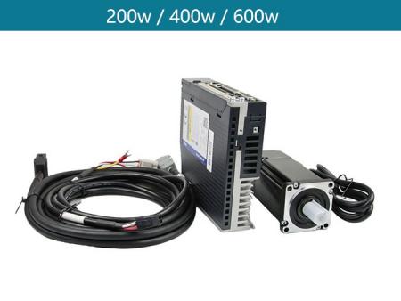
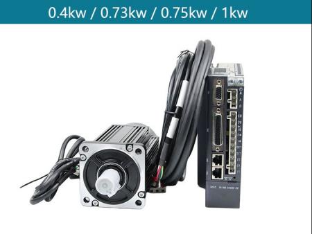
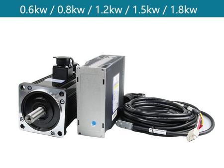
There are many commonly used servo motors , and the selection is not a simple matter. Each type of servo is proficient, and it is very stressful for our learning. The only measure we can take is to choose what we can meet in our daily work. Learn about the most models, and by the way, learn about several models and brands that are more commonly used in the market. The speed of the servo motor is different from one thousand, one thousand five, three thousand, we use the most used 3000RPM AC servo to represent.
In actual use, if a servo is selected or used is 3000RPM, and the required speed is 0-3000 variable speed, then what means can be used to change the current servo speed.
The adjustment of the servo speed depends on what method is used to control and the choice of control method, whether to use pulse control speed, analog control speed or direct drive internal setting control and adjustment speed, the corresponding method is also different.
Corresponding to three different control methods to summarize the speed change:
1 Torque control, the speed is free (varies with load)
Torque control is a commonly used control method. The output torque is set by external analog or direct address assignment, so the corresponding speed is not always certain, because the friction coefficient of the equipment changes, the load The change of will affect the speed output. In this use case, we basically don't need to adjust the speed, because it is automatic adjustment. What we need is the stability of the system, and the torque is stable for a long time.
The set torque can be changed by instantly changing the analog setting, or it can be achieved by changing the value of the corresponding address by means of communication. The application is mainly used in winding and unwinding devices that have strict requirements on the force of the material, such as winding devices or optical fiber pulling equipment. The purpose of using servo is to prevent the change of the winding material from changing the force.
2 Position control, precise positioning, speed and torque can be strictly controlled
In the position control mode, the rotation speed is generally determined by the frequency of externally input pulses, and the rotation angle is determined by the number of pulses. Some servos can directly assign speed and displacement through communication.
Position mode can have very strict control on speed and position, so it is generally used in positioning devices. Application areas such as CNC machine tools, printing machinery and so on.
What is the rated frequency of the PLC or other sending pulses during use? 20KHz, 100KHz, 200KHz, the actual distance that needs to be moved corresponds to the pulse equivalent selected by the servo, and the upper limit running speed and time of the servo moving to the specified position can be calculated.
The servo line speed must be calculated, and only the appropriate servo model can be selected to meet the requirements of the site.
Servo online running speed = command pulse rated frequency × servo upper limit speed
Servo controllers generally have an encoder, and can receive feedback pulses from the encoder. Set the encoder feedback pulse frequency on the speed loop. Set the encoder feedback pulse frequency = encoder feedback pulse number per week × servo motor set speed (R/s) Because the command pulse frequency = encoder feedback pulse frequency/electronic gear ratio, the "command pulse frequency" can also be set to set the servo motor speed.
3. In speed mode, torque is free (varies with load)
Rotation speed can be controlled by analog input or pulse frequency, and positioning can also be carried out in speed mode when the outer loop PID control with upper control device is provided, but the position signal of the motor or the position signal of the direct load must be sent to the upper position. Feedback for calculation purposes.
The speed mode corresponds to the position mode, and the position signal has an error. The position mode signal is provided by the terminal load detection device, which reduces the intermediate transmission error and relatively increases the positioning accuracy of the entire system.
The speed control mode mainly uses the 0-10 voltage signal to control the motor speed. The magnitude of the analog quantity determines the magnitude of the given speed. The positive or negative determines the motor response depends on the speed command gain. It is used in occasions with large load inertia. In speed mode, you need to set the speed loop gain to make the system respond more quickly. It is necessary to take into account the vibration of the equipment when adjusting, and the system vibration should not be caused by the response speed.
When using speed control, you also need to pay attention to the acceleration and deceleration settings. If there is no closed-loop control, zero clamp or proportional control is required to completely stop the motor. When the upper computer is used for position closed loop, the analog value cannot be automatically adjusted to zero.
The control system sends +/-10V analog voltage commands to the servo drive to control the speed. The advantage is that the servo responds quickly, but the disadvantage is that it is more sensitive to on-site interference and the debugging is slightly more complicated. The speed control has a wide range of applications: a continuous speed regulation system that requires fast seat ringing; a closed-loop positioning system from the upper position; a system that requires multiple speeds for rapid switching.
During the use and debugging of the servo system, various unexpected disturbances will occur from time to time, especially for the application of the servo motor that sends pulses.
The following will analyze the types and generation methods of interference from several aspects to achieve targeted anti-interference purposes. I hope everyone will learn and research together.
1. Interference from the power supply
There are various restrictions on the on-site use conditions, and there are usually many complicated situations that need to be habitually avoided, and the cause of the problem should be avoided as much as possible.
In many cases, we will add filters to the power supply module and motion controller of the rotary encoder by adding voltage regulators, isolation transformers and other equipment, change the drive to a DC reactor, and change the low-pass filter time and carrier rate parameters of the drive. , To reduce the interference caused by the introduction of the power supply, and to avoid the failure of the servo control system.
Servo system power lines should be routed separately to shorten the distance between the drive and the motor power line, etc., to avoid interference with the control line and cause drive failure.
2. Interference from the chaos of the grounding system
Grounding is an effective means to improve the anti-interference of electronic equipment. It can restrain the equipment from sending out interference and avoid the influence of external interference. However, wrong grounding will introduce serious interference signals and make the system unable to work normally. The ground wire of the control system generally includes system ground, shield ground, AC ground, and protective ground.
If the grounding system is chaotic, the main interference to the servo system is the uneven distribution of the potential of each grounding point. There is a potential difference between the two ends of the cable shielding section, the grounding wire, the earth, and the grounding points of other equipment, causing ground loop currents. Affect the normal operation of the system.
The key to solving this kind of interference is to distinguish the grounding method and provide a good grounding performance for the system.
The ground wire made by the servo should pay attention to environmental electromagnetic compatibility, and shield high-frequency electromagnetic waves, radio frequency devices, etc.; power noise interference sources should be suppressed and eliminated, such as high-frequency and intermediate-frequency on the same power transformer or distribution bus , High-power rectifier and inverter power devices, etc...
Introduce an unconventional grounding treatment, because the power distribution line inevitably has a large interference source, the driver is installed separately in the cabinet, the installation board uses a non-metal plate, and the ground wires related to the servo driver are suspended, and other measurement systems are reliably grounded. , This might be better.
3. Interference from the system
It is mainly produced by the mutual electromagnetic radiation between the internal components and circuits of the system, such as the mutual radiation of logic circuits, the mutual influence of analog ground and logic ground, and the mismatching use of components.
Signal wires and control wires should be shielded wires, which is beneficial to prevent interference.
When the line is long, for example, the distance exceeds 100 m, the cross section of the wire should be enlarged.
Signal wires and control wires are best placed through pipes to avoid mutual interference with power wires.
The transmission signal is mainly based on the selection of the current signal, and the attenuation and anti-interference of the current signal are relatively good. In practical applications, the sensor output is mostly a voltage signal, which can be converted by a converter.
To filter the DC power supply of the analog weak circuit, you can add two 0.01uF (630V) capacitors, one end is connected to the positive and negative poles of the power supply, and the other end is connected to the chassis and then connected to the earth. Very effective.
When the servo squeaks, it will output high-frequency harmonic interference. You can connect a 0.1u/630v CBB capacitor to the chassis for a test on the P and N ends of the servo drive bus power supply.
The shielding layer of the control line of the board is connected to the 0V of the board, and the driver is not connected. Just pull out a section of the shielding layer and twist it into a strand and expose it to the outside. Use electromagnetic EMI filter, welding anti-interference resistance on the control line, or connect a magnetic ring to the motor power line.
The actual on-site working conditions are much more complicated, and it can only be a specific analysis of specific problems, but in the end there will be a satisfactory solution, but the process experience is different!


View More(Total0)Comment Lists